US4703965A - Integrated circuit placement device vacuum head - Google Patents
Integrated circuit placement device vacuum head Download PDFInfo
- Publication number
- US4703965A US4703965A US06/833,104 US83310486A US4703965A US 4703965 A US4703965 A US 4703965A US 83310486 A US83310486 A US 83310486A US 4703965 A US4703965 A US 4703965A
- Authority
- US
- United States
- Prior art keywords
- housing
- inferior
- orifice
- vacuum
- superior
- Prior art date
- Legal status (The legal status is an assumption and is not a legal conclusion. Google has not performed a legal analysis and makes no representation as to the accuracy of the status listed.)
- Expired - Fee Related
Links
Images
Classifications
-
- H—ELECTRICITY
- H05—ELECTRIC TECHNIQUES NOT OTHERWISE PROVIDED FOR
- H05K—PRINTED CIRCUITS; CASINGS OR CONSTRUCTIONAL DETAILS OF ELECTRIC APPARATUS; MANUFACTURE OF ASSEMBLAGES OF ELECTRICAL COMPONENTS
- H05K13/00—Apparatus or processes specially adapted for manufacturing or adjusting assemblages of electric components
- H05K13/04—Mounting of components, e.g. of leadless components
- H05K13/0404—Pick-and-place heads or apparatus, e.g. with jaws
- H05K13/0408—Incorporating a pick-up tool
- H05K13/0409—Sucking devices
-
- Y—GENERAL TAGGING OF NEW TECHNOLOGICAL DEVELOPMENTS; GENERAL TAGGING OF CROSS-SECTIONAL TECHNOLOGIES SPANNING OVER SEVERAL SECTIONS OF THE IPC; TECHNICAL SUBJECTS COVERED BY FORMER USPC CROSS-REFERENCE ART COLLECTIONS [XRACs] AND DIGESTS
- Y10—TECHNICAL SUBJECTS COVERED BY FORMER USPC
- Y10T—TECHNICAL SUBJECTS COVERED BY FORMER US CLASSIFICATION
- Y10T29/00—Metal working
- Y10T29/53—Means to assemble or disassemble
- Y10T29/5313—Means to assemble electrical device
- Y10T29/53191—Means to apply vacuum directly to position or hold work part
Definitions
- the present invention is generally related to the field of assembling circuit boards employing integrated circuit devices. More narrowly, the invention is directed to apparatus for the placement of electronic components on such host structures. The invention specifically deals with apparatus for picking up, holding and placing surface mount integrated circuit components onto printed circuit boards for their soldering thereto.
- Integrated circuit devices also known as semi-conductors, are used throughout the electronics industry. The importance of the integrated circuit device resides in its multiple and varied uses. They are typically used in printed circuit boards of various configurations. Because a multiplicity of these integrated circuit devices is, as a matter of course, needed to assemble a printed circuit board, and because location of placement is often critical, means to handle the multiplicity of these devices quickly and accurately is important.
- the small size of the integrated circuit device with its fragile leads requires the use of precision and soft-handling instruments to allow for its placement in a particular position on a printed circuit board. Apparatus capable of precise placement are known in the art.
- the small size of the integrated circuit device, in combination with the small size of the leads extending from the main body portion of the circuit device, increases the need for precise placement in order to insure correct connections be formed between the integrated circuit device and the host printed circuit board on which the device is to be mounted.
- Prior apparatus for the placement of such devices have used hollow probes with a connected vacuum source.
- a structure utilizes the hollow probe as a straw-type device which picks up and places the device by application of the vacuum to temporarily hold the integrated circuit device to be mounted to the straw-like device.
- the vacuum is either withdrawn or the integrated circuit device is affixed to the printed circuit board by attachment means.
- the method of attachment usually involves soldering of the leads to their connections on the printed circuit board.
- the present invention is a vacuum head for holding an integrated circuit device of virtually any size for centering on the head prior to the head placing the IC in position at a host circuit board to which the device is to be mounted.
- the apparatus includes a first housing having a common vacuum chamber formed therewithin. A surface of the housing has an orifice formed therethrough, the orifice being aligned with respect to an axis of the housing. The orifice is intended to be engaged with the device to be mounted to the board, and, when vacuum is induced within the vacuum chamber, the component can be "picked" for placement on the board.
- a smaller housing is disposed within the common vacuum chamber of the first housing. The disposition of the second housing is such that it is selectively reciprocable between first and second positions.
- a surface of the second housing having an orifice in fluid communication with the vacuum within the chamber, is retracted within the orifice in the first housing and into the vacuum chamber.
- the surface of the second housing is extended through the orifice of the first housing.
- the first housing is barrel-shaped in form and has an outer tip which defines its orifice.
- the second housing comprises an inner tip assembly aligned along the axis of the barrel-shaped housing for reciprocation along that axis.
- the surface of the barrel-shaped housing in which its orifice is formed would be perpendicular to the axis.
- a seal can be provided to insure that, when the inner tip assembly is projected through the orifice of the barrel housing, vacuum generated within the vacuum chamber is virtually fully applied through the orifice in the inner tip assembly.
- a seat can be provided on an inner surface of the vacuum chamber circumscribing the orifice of the barrel housing.
- the inner tip assembly can be provided with an annular shoulder engageable with this seat.
- An O-ring can be interposed between the seat and shoulder so that, as the inner tip assembly is projected to its second position, the O-ring will be engaged by both the seat and shoulder. Vacuum will, therefore, be directed only to the orifice of the inner tip assembly, since that orifice is in fluid communication with the vacuum chamber. Vacuum will be precluded from passing between the seat and the shoulder.
- the inner tip assembly can take the form of an inner shaft having an aperture, transverse to the orientation of the axis of the barrel housing, formed therethrough. This aperture would be at a location such that the aperture would be in fluid communication with the vacuum chamber even when the annular shoulder of the inner tip assembly were in engagement with the O-ring seal.
- a conduit would, in turn, be provided extending between the aperture, and the orifice of the inner tip assembly in order to convey the vacuum to that orifice.
- the present invention is, thus, an improved vacuum head device for picking and placing various types and sizes of integrated circuits for mounting to host structures such is printed circuit boards. More specific details and advantages obtained in view of these details will become apparent with reference to the DETAILED DESCRIPTION OF THE INVENTION, appended claims, and accompanying drawing.
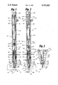
- FIG. 1 is a side sectional view of a vacuum head in accordance with the present invention illustrating the inner tip assembly in its first, or retracted, position;
- FIG. 2 is a view similar to that of FIG. 1 with the inner tip assembly in its second or extended position;
- FIG. 3 is an enlarged sectional detail view taken generally along the line 3--3 of FIG. 2.
- FIGS. 1 and 2 illustrate a vacuum head 10 in accordance with the present invention.
- the invention is shown as being used in cooperation with a pair of holding and centering jaws 12, 14 by which an integrated circuit device 16, 16' is centered on the vacuum head 10 with respect to a central longitudinal axis (not shown) thereof.
- the head 10 comprises an outer housing 18 which has a casing 20 generally circularly cylindrical along much of its length. In operation, the housing would typically be disposed so that the central longitudinal axis thereof was oriented substantially vertically. With such an orientation, a surface 22 of the housing 18 having an orifice 24 therethrough is disposed generally horizontally in a tapered fitting 26 at the lower end of the casing 20.
- the casing 20 is closed at its upper end by an end cap 28, the end cap 28 typically being sealed so that vacuum induced within a chamber 30 defined within the casing 20 will not escape upwardly.
- a vacuum inlet 32 is shown extending into the chamber 30 from the right side of the casing 20.
- FIGS. 1 and 2 show an inner tip assembly 34 enclosed within the barrel housing casing 20 in a concentric relationship.
- the inner tip assembly 34 is intended to be selectively reciprocated along the axis of the outer housing 20 between a first, retracted position, as seen in FIG. 1, and a second, extended position, as seen in FIG. 2. Reciprocation is accomplished in a manner as will be discussed hereinafter.
- the lower end of the outer housing 20 is provided with a fitting 26 which carries a surface 22 through which the orifice 24 is formed.
- the fitting 26 has a channel 36 formed therein, the channel 36 having a diameter slightly larger than that of the the inner tip assembly 34.
- the fitting 26, at its inner end, can carry a plurality of radially inwardly facing, linear bearings 38 for aligning and disposing the inner tip assembly 34 along the axis of the outer housing 18. Since tolerances with regard to the relationship of the inner tip assembly 34 to the outer housing 18 can be critical, precision components would, typically, be used in mounting the tip assembly 34 relative to the outer housing casing 20.
- the fitting 26 could be maintained within the outer housing casing 20 in any appropriate manner. Similarly, any appropriate method or structure for maintaining the linear bearings 38 in place could be employed.
- the figures illustrate a C-ring 40 fitted into an annular groove 42 formed in the inner surface 44 of the fitting 26.
- the figures illustrate employment of an O-ring seal 46 between the fitting 26 and the lower end of the outer housing casing 20 to ensure containment of the vacuum generated within the casing 20 at the interface of these two members.
- the inner tip assembly 34 is disposed for reciprocation between retracted and extended positions.
- An air cylinder 48 is utilized for this purpose.
- the cylinder 48 is located within the outer housing casing 20 at a position intermediate the inner tip assembly 34 and the upper end cap 28.
- the cylinder 48 is suspended from the upper end cap 28 by an extension conduit 50 by which the air is provided to the cylinder 48. It is envisioned that this conduit 50 be made of an appropriate metal. Consequently, the positioning of the cylinder 48 relative to the casing 20 would be relatively stable, since fittings 52, 54 by which the conduit 50 is mounted to the end cap 28 and the cylinder 48 provide relative rigidity.
- the fittings 52, 54 can be sealed by appropriate elastomeric gaskets 56, 58. Consequently, air for actuating the cylinder 48 should not leak into the chamber 30 in which a vacuum is to be induced.
- a reciprocable shaft 60 extending downwardly from the cylinder 48 is coupled to the inner tip assembly 34.
- the positioning of the air cylinder 48 within the outer housing casing 20 is relatively fixed, some flexure of the extension conduit 50 might occur as air is introduced into, and bled from, the air cylinder 48.
- the coupling mechanism by which mating of the air cylinder shaft 60 to the inner tip assembly 34 is accomplished would, it is envisioned, be flexible, since the inner tip assembly 34 is, as previously indicated, rigidly spaced relative to the outer housing casing 20. Any appropriate flexible coupling 62 could be employed.
- the one illustrated is mated to the air cylinder shaft 60 at one of its ends and to the inner tip assembly 34 at its other end. Mating can be effected by use of set screws 64 or other appropriate means.
- a pick and place apparatus employing the vacuum head 10 in accordance with the present invention would bring the vacuum head 10 into engagement with integrated circuit device 16, 16' to be mounted to a structure such as a printed circuit board (not shown). If the IC device 16, 16' is relatively large in size (for example, larger than 0.125 inches square), the larger orifice 24 formed in the fitting 26 of the outer housing 18 could be employed. Air would be provided to the cylinder 48 to operate the piston thereof (not shown) so that the inner tip assembly 34 would be retracted into its first position.
- the jaws 12, 14 of the centering structure can be synchronously operated to close upon the IC device 16, 16' to center it with respect to the axis of the vacuum head 10.
- the centering illustrated in the figures would occur only along one axis.
- a second pair of jaws could be incorporated to center the device along an axis perpendicular to the one along which the jaws 12, 14 illustrated so center.
- the air cylinder 48 can be operated to extend the shaft 60 and, in turn, extend the inner tip assembly 34 so that its lower, distal end will be projected through the orifice 24 in the outer casing fitting 26.
- the vacuum head 10 is lowered into a position to engage a component 16, 16', the device 16, 16' will be engaged by the inner tip assembly 34 rather than the outer housing fitting 26.
- the specific construction of the inner tip assembly 34 is one wherein fluid communication is provided between the vacuum chamber 30 and an orifice 68 at the distal end of the assembly 34.
- a transverse aperture 70 is formed through a solid inner shaft 72 of the inner tip assembly 34 and, immediately, communicates with the vacuum chamber 30.
- a conduit 74 extends downwardly from the aperture 70 to the orifice 68 of the inner tip assembly 34.
- the inner shaft 72 is provided with an oblique, annular shoulder 76.
- This shoulder 76 faces axially downwardly.
- a seat 78 is provided within the vacuum chamber 30 circumscribing the orifice 24 in the fitting 26 of the outer housing 18.
- This shoulder 76 and seat 78 are engagable as the inner tip assembly 34 is actuated in movement to its extended position.
- An O-ring 80 is interposed between the shoulder 76 and seat 78 and positioned on the seat 78 so that, as the inner tip assembly 34 arrives at its second, extended position, the O-ring 80 will be engaged by both the seat 78 and the shoulder 76. Vacuum will, therefore, be precluded from passing other than through the inner tip assembly 34 to the orifice 68 at the distal end thereof.
- the present invention is a versatile vacuum head 10 for accomplishing its intended purpose. Tips can be "changed” rapidly, efficiently, and without sacrificing alignment of the vacuum orifice 24, 68. Further, interruption of placement operations is extremely minimal.
Abstract
Description
Claims (7)
Priority Applications (1)
| Application Number | Priority Date | Filing Date | Title |
|---|---|---|---|
| US06/833,104 US4703965A (en) | 1986-02-25 | 1986-02-25 | Integrated circuit placement device vacuum head |
Applications Claiming Priority (1)
| Application Number | Priority Date | Filing Date | Title |
|---|---|---|---|
| US06/833,104 US4703965A (en) | 1986-02-25 | 1986-02-25 | Integrated circuit placement device vacuum head |
Publications (1)
| Publication Number | Publication Date |
|---|---|
| US4703965A true US4703965A (en) | 1987-11-03 |
Family
ID=25263440
Family Applications (1)
| Application Number | Title | Priority Date | Filing Date |
|---|---|---|---|
| US06/833,104 Expired - Fee Related US4703965A (en) | 1986-02-25 | 1986-02-25 | Integrated circuit placement device vacuum head |
Country Status (1)
| Country | Link |
|---|---|
| US (1) | US4703965A (en) |
Cited By (19)
| Publication number | Priority date | Publication date | Assignee | Title |
|---|---|---|---|---|
| US4815779A (en) * | 1987-08-21 | 1989-03-28 | American Telephone And Telegraph Co. | Method and apparatus for part pickup |
| US4850780A (en) * | 1987-09-28 | 1989-07-25 | Kulicke And Soffa Industries Inc. | Pre-peel die ejector apparatus |
| US4898507A (en) * | 1987-02-05 | 1990-02-06 | Dynapert, Inc. | Apparatus for handling electrical or electronic components |
| US4917568A (en) * | 1987-02-05 | 1990-04-17 | Emhart Industries, Inc. | Suction pick-up apparatus for electrical or electronic components |
| US4990051A (en) * | 1987-09-28 | 1991-02-05 | Kulicke And Soffa Industries, Inc. | Pre-peel die ejector apparatus |
| US5113578A (en) * | 1990-11-29 | 1992-05-19 | Emhart Inc. | Tool tip assembly for surface mount machine |
| EP0607901A1 (en) * | 1993-01-18 | 1994-07-27 | Tenryu Technics Co., Ltd. | Vacuum fixing device for parts |
| US5374158A (en) * | 1990-01-16 | 1994-12-20 | Aetrium, Inc. | Probe and inverting apparatus |
| US5657534A (en) * | 1994-09-16 | 1997-08-19 | Lg Industrial Systems Co., Ltd. | Tool for surface mounting device head |
| US6139078A (en) * | 1998-11-13 | 2000-10-31 | International Business Machines Corporation | Self-aligning end effector for small components |
| US6161886A (en) * | 1996-06-26 | 2000-12-19 | Matsushita Electric Industrial Co., Ltd. | Component mounting head |
| US6298547B1 (en) * | 1997-09-25 | 2001-10-09 | Matsushita Electric Industrial Co., Ltd. | Apparatus for holding component, apparatus for mounting component, and method for mounting component |
| US6328362B1 (en) * | 1999-08-05 | 2001-12-11 | Fuji Machine Mfg. Co., Ltd. | Electric-component mounting head |
| US20010049874A1 (en) * | 1997-09-25 | 2001-12-13 | Osamu Okuda | Apparatus for holding component, and apparatus for mounting component |
| US20060123624A1 (en) * | 2001-05-03 | 2006-06-15 | Infineon Technologies Ag | Placement system for populating a substrate with electronic components |
| US20070228751A1 (en) * | 2006-03-30 | 2007-10-04 | Viavattine Joseph J | Apparatus and method for positioning current collectors in an electrochemical cell |
| US20080066514A1 (en) * | 2006-09-15 | 2008-03-20 | Hon Hai Precision Industry Co., Ltd. | Apparatus for picking and placing workpiece |
| US20130160293A1 (en) * | 2011-12-27 | 2013-06-27 | Samsung Techwin Co., Ltd. | Adsorption head for surface mounting device |
| US9003644B2 (en) | 2012-10-15 | 2015-04-14 | Stmicroelectronics Pte Ltd | PNP apparatus and PNP tool head with direct bonding pressure pick-up tip |
Citations (10)
| Publication number | Priority date | Publication date | Assignee | Title |
|---|---|---|---|---|
| US2789680A (en) * | 1951-09-06 | 1957-04-23 | Fmc Corp | Line divider |
| GB1193921A (en) * | 1968-01-17 | 1970-06-03 | Strachan & Henshaw Ltd | A Suction Cup Assembly for Laminate and Plate Handling |
| US3695461A (en) * | 1970-10-14 | 1972-10-03 | Clyde Corp | Vacuum-actuated transfer device and assembly apparatus |
| US3973682A (en) * | 1974-12-20 | 1976-08-10 | International Business Machines Corporation | Pick up assembly for fragile devices |
| US4135630A (en) * | 1977-12-08 | 1979-01-23 | Universal Instruments Corporation | Centering device for automatic placement of chip components in hybrid circuits |
| US4174847A (en) * | 1977-12-12 | 1979-11-20 | Teledyne, Inc. | Precision centering device |
| US4189137A (en) * | 1978-04-14 | 1980-02-19 | The Mccall Pattern Company | Vacuum pickup device |
| DE3102206A1 (en) * | 1981-01-23 | 1982-08-19 | Siemens AG, 1000 Berlin und 8000 München | Mounting head for mounting electronic components |
| EP0154552A2 (en) * | 1984-03-08 | 1985-09-11 | Dynapert Precima Limited | Head and method for orienting electrical components |
| US4559718A (en) * | 1983-08-02 | 1985-12-24 | Oki Electric Industry Co., Ltd. | Method and apparatus for drying semiconductor wafers |
-
1986
- 1986-02-25 US US06/833,104 patent/US4703965A/en not_active Expired - Fee Related
Patent Citations (10)
| Publication number | Priority date | Publication date | Assignee | Title |
|---|---|---|---|---|
| US2789680A (en) * | 1951-09-06 | 1957-04-23 | Fmc Corp | Line divider |
| GB1193921A (en) * | 1968-01-17 | 1970-06-03 | Strachan & Henshaw Ltd | A Suction Cup Assembly for Laminate and Plate Handling |
| US3695461A (en) * | 1970-10-14 | 1972-10-03 | Clyde Corp | Vacuum-actuated transfer device and assembly apparatus |
| US3973682A (en) * | 1974-12-20 | 1976-08-10 | International Business Machines Corporation | Pick up assembly for fragile devices |
| US4135630A (en) * | 1977-12-08 | 1979-01-23 | Universal Instruments Corporation | Centering device for automatic placement of chip components in hybrid circuits |
| US4174847A (en) * | 1977-12-12 | 1979-11-20 | Teledyne, Inc. | Precision centering device |
| US4189137A (en) * | 1978-04-14 | 1980-02-19 | The Mccall Pattern Company | Vacuum pickup device |
| DE3102206A1 (en) * | 1981-01-23 | 1982-08-19 | Siemens AG, 1000 Berlin und 8000 München | Mounting head for mounting electronic components |
| US4559718A (en) * | 1983-08-02 | 1985-12-24 | Oki Electric Industry Co., Ltd. | Method and apparatus for drying semiconductor wafers |
| EP0154552A2 (en) * | 1984-03-08 | 1985-09-11 | Dynapert Precima Limited | Head and method for orienting electrical components |
Non-Patent Citations (2)
| Title |
|---|
| IBM Technical Disclosure Bulletin; "Vacuum Foot Separator" by T. Barna; vol. 7, No. 2, Jul. 1964. |
| IBM Technical Disclosure Bulletin; Vacuum Foot Separator by T. Barna; vol. 7, No. 2, Jul. 1964. * |
Cited By (28)
| Publication number | Priority date | Publication date | Assignee | Title |
|---|---|---|---|---|
| US4898507A (en) * | 1987-02-05 | 1990-02-06 | Dynapert, Inc. | Apparatus for handling electrical or electronic components |
| US4917568A (en) * | 1987-02-05 | 1990-04-17 | Emhart Industries, Inc. | Suction pick-up apparatus for electrical or electronic components |
| US4815779A (en) * | 1987-08-21 | 1989-03-28 | American Telephone And Telegraph Co. | Method and apparatus for part pickup |
| US4850780A (en) * | 1987-09-28 | 1989-07-25 | Kulicke And Soffa Industries Inc. | Pre-peel die ejector apparatus |
| US4990051A (en) * | 1987-09-28 | 1991-02-05 | Kulicke And Soffa Industries, Inc. | Pre-peel die ejector apparatus |
| US5374158A (en) * | 1990-01-16 | 1994-12-20 | Aetrium, Inc. | Probe and inverting apparatus |
| US5113578A (en) * | 1990-11-29 | 1992-05-19 | Emhart Inc. | Tool tip assembly for surface mount machine |
| EP0607901A1 (en) * | 1993-01-18 | 1994-07-27 | Tenryu Technics Co., Ltd. | Vacuum fixing device for parts |
| US5657534A (en) * | 1994-09-16 | 1997-08-19 | Lg Industrial Systems Co., Ltd. | Tool for surface mounting device head |
| CN1080083C (en) * | 1994-09-16 | 2002-02-27 | Lg产电株式会社 | Tool for surface mounting device head and automatic changing apparatus thereof |
| US6161886A (en) * | 1996-06-26 | 2000-12-19 | Matsushita Electric Industrial Co., Ltd. | Component mounting head |
| US20010049874A1 (en) * | 1997-09-25 | 2001-12-13 | Osamu Okuda | Apparatus for holding component, and apparatus for mounting component |
| US6895662B2 (en) | 1997-09-25 | 2005-05-24 | Matsushita Electric Industrial Co., Ltd. | Apparatus for holding and mounting a component |
| US20050183263A1 (en) * | 1997-09-25 | 2005-08-25 | Osamu Okuda | Apparatus for holding and mounting a component |
| US7059036B2 (en) | 1997-09-25 | 2006-06-13 | Matsushita Electric Industrial Co., Ltd. | Apparatus for holding and mounting a component |
| US6298547B1 (en) * | 1997-09-25 | 2001-10-09 | Matsushita Electric Industrial Co., Ltd. | Apparatus for holding component, apparatus for mounting component, and method for mounting component |
| US6163950A (en) * | 1998-11-13 | 2000-12-26 | International Business Machines Corporation | Method of aligning small components using self-aligning end effector |
| US6139078A (en) * | 1998-11-13 | 2000-10-31 | International Business Machines Corporation | Self-aligning end effector for small components |
| US6328362B1 (en) * | 1999-08-05 | 2001-12-11 | Fuji Machine Mfg. Co., Ltd. | Electric-component mounting head |
| US7500305B2 (en) * | 2001-05-03 | 2009-03-10 | Qimonda Ag | Placement system for populating a substrate with electronic components |
| US20060123624A1 (en) * | 2001-05-03 | 2006-06-15 | Infineon Technologies Ag | Placement system for populating a substrate with electronic components |
| US20070228751A1 (en) * | 2006-03-30 | 2007-10-04 | Viavattine Joseph J | Apparatus and method for positioning current collectors in an electrochemical cell |
| US7556298B2 (en) | 2006-03-30 | 2009-07-07 | Medtronic, Inc. | Apparatus and method for positioning current collectors in an electrochemical cell |
| US20080066514A1 (en) * | 2006-09-15 | 2008-03-20 | Hon Hai Precision Industry Co., Ltd. | Apparatus for picking and placing workpiece |
| US7722309B2 (en) * | 2006-09-15 | 2010-05-25 | Hon Hai Precision Industry Co., Ltd. | Apparatus for picking and placing workpiece |
| US20130160293A1 (en) * | 2011-12-27 | 2013-06-27 | Samsung Techwin Co., Ltd. | Adsorption head for surface mounting device |
| US9258936B2 (en) * | 2011-12-27 | 2016-02-09 | Hanwha Techwin Co., Ltd. | Adsorption head for surface mounting device |
| US9003644B2 (en) | 2012-10-15 | 2015-04-14 | Stmicroelectronics Pte Ltd | PNP apparatus and PNP tool head with direct bonding pressure pick-up tip |
Similar Documents
| Publication | Publication Date | Title |
|---|---|---|
| US4703965A (en) | Integrated circuit placement device vacuum head | |
| US4852247A (en) | Suction pick-up apparatus for electrical or electronic components | |
| US4763941A (en) | Automatic vacuum gripper | |
| US4728135A (en) | Component sucking and holding machine | |
| KR960006740A (en) | Electronic Component Surface Mount Device | |
| US5027063A (en) | Vacuum-actuated test fixture for testing electronic components | |
| US6467824B2 (en) | Floating seal pick and place system and unit therefor | |
| US5038466A (en) | Multifunctional end effector and method of converting single purpose robot arm | |
| JPH04289079A (en) | Forward end instrument of tool for use on surface mounting device | |
| KR20210086451A (en) | Rotatable cushioning pick-and-place device | |
| JPH01121190A (en) | Element positioning device | |
| US5456007A (en) | Assist method and apparatus for fitting close tolerance valves into bores | |
| JPS61203250A (en) | Preparation and pre-setting device for machine tool | |
| CN110082045B (en) | Auxiliary tool clamp for detecting tightness of cylindrical part | |
| JPH0475828A (en) | Suction structure for screw | |
| JPH09150950A (en) | Parts conveying device | |
| CN110202399A (en) | A kind of clamping device of the airtight detection of band | |
| JPH0423399A (en) | Centering chuck mechanism for electronic component use | |
| JP2816114B2 (en) | Vacuum gripper and IC test handler | |
| CN211061719U (en) | Gas circuit interface device for air data computer | |
| RU1812048C (en) | Device for mounting flexible rings in shaft grooves | |
| JPH023400Y2 (en) | ||
| US20240138073A1 (en) | Clamping device with pivoting retainer | |
| US6864678B2 (en) | Nestless plunge mechanism for semiconductor testing | |
| JPH06155211A (en) | Vacuum sucking table |
Legal Events
| Date | Code | Title | Description |
|---|---|---|---|
| AS | Assignment |
Owner name: MICRO COMPONENT TECHNOLOGY, INC., P.O. BOX 64013, Free format text: ASSIGNMENT OF ASSIGNORS INTEREST.;ASSIGNORS:LEE, JOHN S.;LOZINSKI, DANIEL L.;REEL/FRAME:004699/0003 Effective date: 19860223 Owner name: MICRO COMPONENT TECHNOLOGY, INC., A CORP. OF DE., Free format text: ASSIGNMENT OF ASSIGNORS INTEREST;ASSIGNORS:LEE, JOHN S.;LOZINSKI, DANIEL L.;REEL/FRAME:004699/0003 Effective date: 19860223 |
|
| AS | Assignment |
Owner name: MARINE MIDLAND BUSINESS LOANS, INC., 1101 WALNUT S Free format text: SECURITY INTEREST;ASSIGNOR:MICRO COMPONENT TECHNOLOGY, INC., A DE. CORP.;REEL/FRAME:004870/0343 Effective date: 19880322 Owner name: MARINE MIDLAND BUSINESS LOANS, INC.,MISSOURI Free format text: SECURITY INTEREST;ASSIGNOR:MICRO COMPONENT TECHNOLOGY, INC., A DE. CORP.;REEL/FRAME:004870/0343 Effective date: 19880322 |
|
| REMI | Maintenance fee reminder mailed | ||
| LAPS | Lapse for failure to pay maintenance fees | ||
| FP | Lapsed due to failure to pay maintenance fee |
Effective date: 19911103 |
|
| STCH | Information on status: patent discontinuation |
Free format text: PATENT EXPIRED DUE TO NONPAYMENT OF MAINTENANCE FEES UNDER 37 CFR 1.362 |