US4700307A - Feature navigation system and method - Google Patents
Feature navigation system and method Download PDFInfo
- Publication number
- US4700307A US4700307A US06/514,210 US51421083A US4700307A US 4700307 A US4700307 A US 4700307A US 51421083 A US51421083 A US 51421083A US 4700307 A US4700307 A US 4700307A
- Authority
- US
- United States
- Prior art keywords
- vehicle
- feature
- linear
- features
- flight path
- Prior art date
- Legal status (The legal status is an assumption and is not a legal conclusion. Google has not performed a legal analysis and makes no representation as to the accuracy of the status listed.)
- Expired - Lifetime
Links
Images


Classifications
-
- G—PHYSICS
- G01—MEASURING; TESTING
- G01C—MEASURING DISTANCES, LEVELS OR BEARINGS; SURVEYING; NAVIGATION; GYROSCOPIC INSTRUMENTS; PHOTOGRAMMETRY OR VIDEOGRAMMETRY
- G01C21/00—Navigation; Navigational instruments not provided for in groups G01C1/00 - G01C19/00
- G01C21/005—Navigation; Navigational instruments not provided for in groups G01C1/00 - G01C19/00 with correlation of navigation data from several sources, e.g. map or contour matching
-
- G—PHYSICS
- G05—CONTROLLING; REGULATING
- G05D—SYSTEMS FOR CONTROLLING OR REGULATING NON-ELECTRIC VARIABLES
- G05D1/00—Control of position, course or altitude of land, water, air, or space vehicles, e.g. automatic pilot
- G05D1/02—Control of position or course in two dimensions
- G05D1/0202—Control of position or course in two dimensions specially adapted to aircraft
Definitions
- This invention relates in general to aircraft navigation and, more specifically, to a navigation system using sequences of linear feature navigation updates to correct a basic inertial navigation system.
- inertial navigation using precision accelerometers and gyroscopes greatly increased the accuracy of navigating aircraft, manned and unmanned, over long distances. While these systems are generally sufficiently accurate for manned aircraft, where the pilot could use visual aids to correct for small errors near the target, destination airport, etc., they have sufficient gyro drift and other errors to cause significant target error for unmanned vehicles, such as cruise missiles, flying long distances.
- an inertial navigation system is used to keep the air vehicle nearly on the intended flight path.
- a terrain elevation map which had been earlier prepared, of selected areas along the flight path is stored in computer memory.
- a radar altimeter senses changes in ground contour and compares them to the stored terrain map.
- the computer matches the actual sensed terrain with one path across the mapped area, determining the actual flight path and the degree of error.
- the inertial navigation system is thus updated to return the vehicle to the intended flight path.
- a similar method used digital scene matching. This technique compares a sensed scene, taken by a TV sensor, with a reference scene.
- an airborne vehicle navigation method in which maps of linear features (e.g., roads, railroads, canals, or the like) are prepared and stored in memory covering discrete areas along a proposed flight path.
- the vehicle is launched and flown towards the first area by another navigation system, such as inertial navigation and sensors, and sensors on the vehicle detect linear ground features as the vehicle passes over them and compares them to the mapped features to determine the accumulated navigation error between launch and the first mapped area.
- the path of the vehicle is corrected to compensate for the error and the vehicle is directed toward the next mapped area.
- navigation updates can be made from single linear features. Also, the vehicle can track along a single linear feature, if desired.
- FIG. 1 is a schematic representation of an airborne vehicle flight path using linear feature recognition
- FIGS. 2(a) through 2(d) form a simplified schematic chart illustrating downtrack position determination through a series of linear feature crossings
- FIGS. 3(a) and 3(b) are schematic representations of an airborne vehicle's flight path over a number of linear features where the initial position error is very large (considering both downtrack and crosstrack errors);
- FIG. 4 is a schematic representation of the use of a linear feature leading directly to the destination
- FIG. 5 is a schematic representation of the use of a linear feature leading to an area near the destination
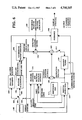
- FIG. 6 is a schematic block diagram of the integrated linear feature navigation system.
- FIG. 7 is a schematic representation of an overall airborne vehicle flight path using both single feature and network feature navigation updates.
- FIG. 1 there is seen a schematic representation of the flight path 8 of an airborne vehicle 10 (here, a cruise missile) past three linear geographic features, a road 12, a canal 14 and a railroad 16.
- an airborne vehicle 10 here, a cruise missile
- Vehicle 10 has been flying under some conventional navigation system such as inertial navigation, which is sufficiently precise so that it is known that the vehicle is somewhere within an area of initial position uncertainty indicated by solid circle 18.
- the degree of uncertainty in this case is sufficiently limited that it is known that road 12 is the first linear feature being encountered.
- the sensor on vehicle 10 detects the presence and direction of road 12.
- the sensor may be an imaging infrared laser radar, a video camera or the like. Since it is not known precisely where road 12 is crossed, position uncertainty is reduced only in the direction perpendicular to the road. This reduction is illustrated by the change from the initial circular area (indicated by broken circle 20) to the solid ellipse 22 at the first feature crossing. The width of this ellipse 22 depends only on processing and reference map errors, while the length is determined by intersection of road 12 with the initial uncertainty circle 20.
- the second linear feature, canal 14 is crossed.
- the navigation error ellipse from the first crossing is intersected with canal 14 as indicated by second broken ellipse 24. Since the second feature (canal 14) is not parallel to the first (road 12), the resulting uncertainty indicated by second solid ellipse 26 is again reduced in size. For clarity of illustration, a broken line indication of road 12 is shown with broken ellipse 24.
- the navigation error ellipse 28 is again reduced to solid ellipse 30 having a length along railroad 16 which intersects broken ellipse 18.
- each linear feature in sequence reduces the vehicle's position error to a value which approaches the reference location (mapped feature location) error. The only constraint is that the sequence of crossed linear features not be parallel.
- the vehicle flight path deviation from the desired flight path is known and the vehicle inertial navigation system can be corrected to return the vehicle to the desired flight path.
- the vehicle position error When the vehicle position error is extremely large, such as after a long over-water flight or before the first navigation update is made, it may not be known which of the mapped linear features is being detected. For example, if a road and a canal intersect on the map, it may not be known whether the first feature is the canal on one side of the intersection point or the road on the other side. Or, the vehicle might be further downrange than expected and be past the expected feature when feature sensing is begun. In second case a feature sequence matching technique as schematically illustrated in a simple one-dimensional example in FIG. 2 may be used.
- the technique illustrated in FIG. 2 depends only on detecting a linear feature crossing, not on detecting orientation.
- the "one-dimensional" locating method illustrated in FIG. 2 is suitable where the flight path is known with some accuracy, but the distance traveled is relatively known.
- the initial uncertainty is schematically indicated by the area within broken line 31.
- the instant vehicle 10 crosses a linear feature the current position is recorded and saved in memory.
- the uncertainty in the downrange direction is so large that vehicle 10 (indicated by solid dot 32) could be anywhere along flight path 34 between any of the linear future crossings 36 and 48.
- a first linear feature which could be any of the features 36 and 48, as indicated by the open dots 50-62.
- Vehicle 10 has actually moved to feature 44, but its location has not yet been ascertained by the vehicle.
- Vehicle 10 continuing along flight path 34, crosses the next linear feature at line 46, here 2 kilometers from the first. As illustrated in FIG. 2(c), there are three pairs of crossings spaced substantially 2 KM apart, 28-30, 44-46 and 46-48. Thus, vehicle 10 could be at any of three locations 54, 60 and 62. While vehicle 10 now is actually at line 46, this position is still not confirmed.
- FIG. 3 schematically illustrates an airborne vehicle 10 flying along flight path 64 over a mapped area having many intersecting linear features generally designated 66.
- the initial position of vehicle 10 could be anywhere within initial uncertainty circle 68.
- circle 68 moves with vehicle 10 as vehicle 10 flys along path 64.
- vehicle 10 crosses the first feature at point 70 the crossing is recorded and saved.
- vehicle sensors will record the distance and compass heading between points 70 and 72, which give a position change vector ⁇ . All positions on the map which correspond to a feature crossing simultaneously at points 70 and 72 can be determined by shifting the map network through an X, Y (i.e., vector) distance ⁇ and recording all intersection positions.
- FIG. 3(b) illustrates the first step in this process, with the shifted map being shown in broken lines generally at 76.
- the vehicle here is moving from left to right, from point 70 to point 72 as in FIG. 3(a).
- the shift distance and angle corresponds to ⁇ .
- "votes" for additional locations occur. Votes at incorrect locations tend to be randomly distributed and do not accumulate. Eventually, the votes converge to the actual location, at the N th point, where N is selected to give the desired certainty, considering variables such as map accuracy, etc.
- the airborne vehicle navigates to the terminal point using basically inertial navigation with periodic linear feature navigation updates and corrections.
- the linear feature navigation method can be used directly for terminal guidance.
- the sensors and on-board processing of vehicle 10 can detect the position of a linear feature relative to the vehicle and create guidance commands which cause the linear feature to be tracked.
- the sensors cover a generally fan-shaped area 88 ahead of vehicle 10. If the linear feature leads directly to the terminal point 90, such as road 92 in FIG. 4, vehicle can follow it all the way. Alternately, as seen in FIG.
- a straight segment 94 of a road which passes close to terminal point 90 and has a crossing linear feature 96, can be used as a "gun barrel” which points the vehicle towards terminal point 90.
- vehicle 10 flies along rod 94, it is caused to fly a straight path by straight segment 94 and senses cross road 96.
- the vehicle controller can be set to perform a pre-planned turn maneuver at a selected distance ⁇ X downrange of cross road 96.
- the preplanned turn of ⁇ ⁇ degrees will aim vehicle 10 directly at terminal point 90, which could be a target for a cruise missile vehicle 10 or an airport approach where vehicle 10 is a manned airplane.
- This technique requires that the relative position between the linear features and the terminal point be accurately known.
- the components of the linear feature navigation system and their operational relationships are provided in block diagram form in FIG. 6.
- the components used in the system are all conventional, used for other purposes in present missile and aircraft systems.
- An imaging sensor 100 such as laser radar or a television camera provides images of linear features below the vehicle which are processed by an image acquisition and/or tracking algorithm.
- the on-board processing algorithm determines two separated points which define the feature orientation/position relative to the sensor image frame.
- Such algorithms have been described by M.A. Fischler et al., "Detection of Roads and Linear Structures In Aerial Imagery by Computer” Proceedings: Image Understanding Workshop, November 1979, available from Science Applications Inc., Report No. SAI-80-974-WA.
- the feature orientation is converted to navigation coordinates using vehicle altitude information from the inertial navigation system and range information, if available.
- this coordinate transformation 104 will be accurate if the sensor is pointed straight down. If passive forward looking sensing is used, the range to the image must be estimated from on-board inertial navigation data. Alternately, if sensor 100 is an active sensor such as a laser radar system, direct range estimates will be provided. A navigation update measurement is determined by differencing at signal point 106 the sensed linear feature orientation vector with the reference orientation vector 108 of the feature stored in the vehicle's guidance system.
- each feature crossing detected by the image processing algorithm sends a feature crossing indicator time flag to the inertial navigation system 112 so that the current position of the vehicle is marked.
- This provides vector position shift information fed back from inertial navigation 112 to network position estimate 114, together with the reference map 115, which is used to determine the candidate positions used in the voting procedures described above.
- the current position estimate from this procedure is differenced at signal point 118 with the current navigation position estimate to form the measurement which is applied to Kalman filter 110 through signal point 120 and, after corrections from Kalman filter 110 are returned to navigation 112, to vehicle guidance 124.
- switch 101 is connected through contact 122 to the feature tracking system 126 with the algorithm operating directly on image data to determine the feature position in the image frame.
- Any conventional line tracking method may be used such as that described in the Fischer et al. article referenced above.
- the image position in the frame is fed to guidance 124, which steers the vehicle to keep the image centered in the frame.
- guidance 124 which steers the vehicle to keep the image centered in the frame.
- the vehicle needs to know the correct downrange point at which to execute the ⁇ turn (as shown in FIG. 5 to achieve precision overflight of the terminal point. This can be determined by monitoring the distanced traveled ( ⁇ X) beyond the cross-feature update (road 96 in FIG. 5), or by observing when the feature begins to turn out of the image.
- FIG. 7 The integrated operation of the three systems (network position estimate 114, single feature acquisition 102 and feature tracking 126) for a typical manned aircraft or missile mission is illustrated in FIG. 7.
- a network update 130 is performed first to reduce the large position uncertainty which may have occurred since launch or a long overwater flight portion. This initial coarse fix is performed as described in conjunction with FIGS. 3(a) and 3(b), above.
- Single feature updates are performed periodically enroute, as indicated by enlarged section 132. So long as the vehicle remains within a corridor indicated by line 134, accurate updates can be obtained from single features, as described in conjunction with FIGS. 1 and 2, above.
- Single linear feature navigation is unique among navigation updata methods because it can derive position updates using only one-dimensional data, whereas prior methods require at least two-dimensions data. Since linear features are quite prevalent and the single point mapping system uses relatively little computer memory, frequent navigation updates (on the order of twice a minute) are possible. With these frequent updates, the inertial navigation system has little time to drift off course. Thus, lightweight, simple and inexpensive inertial navigation systems can be used compared to those required for TERCOM systems where updates typically average 2 to 3 times per hour.
- Occasional network updates may be provided, such as at 138 and 140 to assure that the desired flight path is maintained even if the vehicle should stray out of corridor 134, such as after flying a distance over water or over an area with few linear features.
- final direction can be provided by another network update, if desired, or the direct use of features as described in FIGS. 4 and 5 can be used.
- feature tracking as shown in FIG. 4 can be used.
- vehicle sensors pick up road 146
- the vehicle is caused to fly along the road to target 142.
- the accuracy achieved by tracking features to the terminal point is better than one-half of the width of the feature, e.g., the road, railroad etc., being tracked. This accuracy exceeds that obtained from any other current navigation methods.
Abstract
Description
Claims (25)
Priority Applications (1)
| Application Number | Priority Date | Filing Date | Title |
|---|---|---|---|
| US06/514,210 US4700307A (en) | 1983-07-11 | 1983-07-11 | Feature navigation system and method |
Applications Claiming Priority (1)
| Application Number | Priority Date | Filing Date | Title |
|---|---|---|---|
| US06/514,210 US4700307A (en) | 1983-07-11 | 1983-07-11 | Feature navigation system and method |
Publications (1)
| Publication Number | Publication Date |
|---|---|
| US4700307A true US4700307A (en) | 1987-10-13 |
Family
ID=24046242
Family Applications (1)
| Application Number | Title | Priority Date | Filing Date |
|---|---|---|---|
| US06/514,210 Expired - Lifetime US4700307A (en) | 1983-07-11 | 1983-07-11 | Feature navigation system and method |
Country Status (1)
| Country | Link |
|---|---|
| US (1) | US4700307A (en) |
Cited By (48)
| Publication number | Priority date | Publication date | Assignee | Title |
|---|---|---|---|---|
| WO1988001409A1 (en) * | 1986-08-20 | 1988-02-25 | Grumman Aerospace Corporation | Distributed kalman filter |
| US4805108A (en) * | 1986-02-12 | 1989-02-14 | Messerschmitt-Bolkow-Blohm Gmbh | Low flight method for automatic course determination |
| US4818990A (en) * | 1987-09-11 | 1989-04-04 | Fernandes Roosevelt A | Monitoring system for power lines and right-of-way using remotely piloted drone |
| US4891762A (en) * | 1988-02-09 | 1990-01-02 | Chotiros Nicholas P | Method and apparatus for tracking, mapping and recognition of spatial patterns |
| US4897660A (en) * | 1986-01-14 | 1990-01-30 | R & D Associates | Structure resonant radar detection apparatus and method |
| US4907001A (en) * | 1987-08-21 | 1990-03-06 | Geophysical Survey Systems, Inc. | Extraction of radar targets from clutter |
| US4914734A (en) * | 1989-07-21 | 1990-04-03 | The United States Of America As Represented By The Secretary Of The Air Force | Intensity area correlation addition to terrain radiometric area correlation |
| FR2648904A1 (en) * | 1989-06-22 | 1990-12-28 | Telecommunications Sa | Device for determining the position of an aircraft with respect to the terrain over which it is flying |
| US4992797A (en) * | 1984-07-10 | 1991-02-12 | Norges Teknisk-Naturvitenskapelige Forskningsrad | Method of detection and identification of one or more remote objects |
| EP0427431A2 (en) * | 1989-11-08 | 1991-05-15 | Smiths Industries Public Limited Company | Navigation systems |
| US5047777A (en) * | 1989-05-12 | 1991-09-10 | Dornier Luftfahrt Gmbh | Linear method of navigation |
| US5128874A (en) * | 1990-01-02 | 1992-07-07 | Honeywell Inc. | Inertial navigation sensor integrated obstacle detection system |
| EP0522829A2 (en) * | 1991-07-12 | 1993-01-13 | Pioneer Electronic Corporation | Movement control system and movement monitoring system for moving body |
| US5208757A (en) * | 1990-01-12 | 1993-05-04 | Societe Anonyme Dite: Aerospatiale Societe Nationale Industrielle | Airborne system for determining the position of an aerial vehicle and its applications |
| US5422828A (en) * | 1991-12-18 | 1995-06-06 | Choate; William C. | Method and system for image-sequence-based target tracking and range estimation |
| DE3830496C1 (en) * | 1988-09-08 | 1996-09-19 | Daimler Benz Aerospace Ag | Target detection and tracking device for aircraft navigation |
| US5576964A (en) * | 1992-11-30 | 1996-11-19 | Texas Instruments Incorporated | System and method for relating a passive sensor to a geographic environment |
| US5781146A (en) * | 1996-03-11 | 1998-07-14 | Imaging Accessories, Inc. | Automatic horizontal and vertical scanning radar with terrain display |
| US5801970A (en) * | 1995-12-06 | 1998-09-01 | Martin Marietta Corporation | Model-based feature tracking system |
| GB2335324A (en) * | 1998-03-13 | 1999-09-15 | Marconi Gec Ltd | Locating flying body |
| US6082666A (en) * | 1997-12-03 | 2000-07-04 | Raytheon Company | System for accurately determining missile vertical velocity and altitude |
| US6218980B1 (en) * | 1982-09-13 | 2001-04-17 | Mcdonnell Douglas Corporation | Terrain correlation system |
| US20020196339A1 (en) * | 2001-03-13 | 2002-12-26 | Andrew Heafitz | Panoramic aerial imaging device |
| US6744397B1 (en) * | 2003-06-11 | 2004-06-01 | Honeywell International, Inc. | Systems and methods for target location |
| US20040112238A1 (en) * | 2002-12-13 | 2004-06-17 | Sandia National Laboratories | System for controlling activation of remotely located device |
| US6804726B1 (en) * | 1996-05-22 | 2004-10-12 | Geovector Corporation | Method and apparatus for controlling electrical devices in response to sensed conditions |
| US20050040280A1 (en) * | 2003-08-19 | 2005-02-24 | Hua Cuong Tu | Multi-sensor guidance system for extreme force launch shock applications |
| WO2005119178A1 (en) * | 2004-06-02 | 2005-12-15 | Athena Technologies, Inc. | Image-augmented inertial navigation system (iains) and method |
| US20060167625A1 (en) * | 2005-01-25 | 2006-07-27 | Samsung Electronics Co., Ltd. | Method for finding path in a navigation system |
| US20070093945A1 (en) * | 2005-10-20 | 2007-04-26 | Grzywna Jason W | System and method for onboard vision processing |
| US20070179685A1 (en) * | 2005-09-29 | 2007-08-02 | Mark Milam | Trajectory generation using non-uniform rational B-splines |
| DE102006007006A1 (en) * | 2006-02-15 | 2007-08-16 | Eads Deutschland Gmbh | Method for database-supported estimation of an output variable in a k-dimensional value range |
| WO2008009966A2 (en) * | 2006-07-21 | 2008-01-24 | Trw Limited | Determining the location of a vehicle on a map |
| DE102007054950A1 (en) * | 2007-11-17 | 2009-08-06 | Lfk-Lenkflugkörpersysteme Gmbh | Method for supporting the automatic navigation of a low-flying missile |
| US20100125390A1 (en) * | 2005-11-23 | 2010-05-20 | Trw Automotive U.S. L.L.C. | Electrical power assisted steering system |
| US20100305782A1 (en) * | 2009-05-27 | 2010-12-02 | David Linden | Airborne right of way autonomous imager |
| WO2011023246A1 (en) * | 2009-08-25 | 2011-03-03 | Tele Atlas B.V. | A vehicle navigation system and method |
| WO2011047888A1 (en) * | 2009-10-19 | 2011-04-28 | Metaio Gmbh | Method of providing a descriptor for at least one feature of an image and method of matching features |
| US20110257885A1 (en) * | 2010-04-16 | 2011-10-20 | David Allan Tuck | Method and apparatus for geographically aiding navigation satellite system solution |
| US20120296497A1 (en) * | 2011-05-18 | 2012-11-22 | Hon Hai Precision Industry Co., Ltd. | Unmanned aerial vehicle and method for controlling the unmanned aerial vehicle |
| US8773299B1 (en) * | 2009-09-29 | 2014-07-08 | Rockwell Collins, Inc. | System and method for actively determining obstacles |
| CN106885576A (en) * | 2017-02-22 | 2017-06-23 | 哈尔滨工程大学 | A kind of AUV course-line deviation methods of estimation based on multiple spot terrain match positioning |
| CN108801241A (en) * | 2017-04-07 | 2018-11-13 | 辉达公司 | Autonomous path navigation is executed using deep neural network |
| US10240934B2 (en) | 2014-04-30 | 2019-03-26 | Tomtom Global Content B.V. | Method and system for determining a position relative to a digital map |
| EP3567343A1 (en) * | 2018-05-08 | 2019-11-13 | Honeywell International Inc. | System and methods for reducing the map search space requirements in a vision-inertial navigation system |
| US10739142B2 (en) | 2016-09-02 | 2020-08-11 | Apple Inc. | System for determining position both indoor and outdoor |
| US10948302B2 (en) | 2015-08-03 | 2021-03-16 | Tomtom Global Content B.V. | Methods and systems for generating and using localization reference data |
| US11281221B2 (en) | 2017-04-07 | 2022-03-22 | Nvidia Corporation | Performing autonomous path navigation using deep neural networks |
Citations (8)
| Publication number | Priority date | Publication date | Assignee | Title |
|---|---|---|---|---|
| US2541277A (en) * | 1946-02-02 | 1951-02-13 | Bendix Aviat Corp | Navigational control system |
| US3328795A (en) * | 1959-11-18 | 1967-06-27 | Ling Temco Vought Inc | Fixtaking means and method |
| US3636323A (en) * | 1970-05-01 | 1972-01-18 | Atomic Energy Commission | Geographic position locator |
| US3879728A (en) * | 1959-03-13 | 1975-04-22 | Maxson Electronics Corp | Digital map matching |
| US4175285A (en) * | 1967-08-25 | 1979-11-20 | Thomson-Csf | Navigational system of high-speed aircraft |
| US4347511A (en) * | 1979-04-11 | 1982-08-31 | Messerschmitt-Bolkow-Blohm Gesellschaft Mit Beschrankter Haftung | Precision navigation apparatus |
| US4368456A (en) * | 1979-01-09 | 1983-01-11 | Emi Limited | Apparatus for correlating successive images of a scene |
| US4494200A (en) * | 1981-01-14 | 1985-01-15 | Matra | Process and apparatus for fixing the position of a moving vehicle on a map |
-
1983
- 1983-07-11 US US06/514,210 patent/US4700307A/en not_active Expired - Lifetime
Patent Citations (8)
| Publication number | Priority date | Publication date | Assignee | Title |
|---|---|---|---|---|
| US2541277A (en) * | 1946-02-02 | 1951-02-13 | Bendix Aviat Corp | Navigational control system |
| US3879728A (en) * | 1959-03-13 | 1975-04-22 | Maxson Electronics Corp | Digital map matching |
| US3328795A (en) * | 1959-11-18 | 1967-06-27 | Ling Temco Vought Inc | Fixtaking means and method |
| US4175285A (en) * | 1967-08-25 | 1979-11-20 | Thomson-Csf | Navigational system of high-speed aircraft |
| US3636323A (en) * | 1970-05-01 | 1972-01-18 | Atomic Energy Commission | Geographic position locator |
| US4368456A (en) * | 1979-01-09 | 1983-01-11 | Emi Limited | Apparatus for correlating successive images of a scene |
| US4347511A (en) * | 1979-04-11 | 1982-08-31 | Messerschmitt-Bolkow-Blohm Gesellschaft Mit Beschrankter Haftung | Precision navigation apparatus |
| US4494200A (en) * | 1981-01-14 | 1985-01-15 | Matra | Process and apparatus for fixing the position of a moving vehicle on a map |
Non-Patent Citations (4)
| Title |
|---|
| S 20060044 (10/80) Lerche, "Onboard and Ground Test of Autonomous Navigation System Based on Terrain Correlation". |
| S 20060044 (10/80) Lerche, Onboard and Ground Test of Autonomous Navigation System Based on Terrain Correlation . * |
| S 21110031, Optical Eng. (4/82) vol. 21, No. 2, pp. 370 375, Dron. * |
| S 21110031, Optical Eng. (4/82) vol. 21, No. 2, pp. 370-375, Dron. |
Cited By (90)
| Publication number | Priority date | Publication date | Assignee | Title |
|---|---|---|---|---|
| US6218980B1 (en) * | 1982-09-13 | 2001-04-17 | Mcdonnell Douglas Corporation | Terrain correlation system |
| US4992797A (en) * | 1984-07-10 | 1991-02-12 | Norges Teknisk-Naturvitenskapelige Forskningsrad | Method of detection and identification of one or more remote objects |
| US4897660A (en) * | 1986-01-14 | 1990-01-30 | R & D Associates | Structure resonant radar detection apparatus and method |
| US4805108A (en) * | 1986-02-12 | 1989-02-14 | Messerschmitt-Bolkow-Blohm Gmbh | Low flight method for automatic course determination |
| WO1988001409A1 (en) * | 1986-08-20 | 1988-02-25 | Grumman Aerospace Corporation | Distributed kalman filter |
| US4907001A (en) * | 1987-08-21 | 1990-03-06 | Geophysical Survey Systems, Inc. | Extraction of radar targets from clutter |
| US4818990A (en) * | 1987-09-11 | 1989-04-04 | Fernandes Roosevelt A | Monitoring system for power lines and right-of-way using remotely piloted drone |
| US4891762A (en) * | 1988-02-09 | 1990-01-02 | Chotiros Nicholas P | Method and apparatus for tracking, mapping and recognition of spatial patterns |
| DE3830496C1 (en) * | 1988-09-08 | 1996-09-19 | Daimler Benz Aerospace Ag | Target detection and tracking device for aircraft navigation |
| US5047777A (en) * | 1989-05-12 | 1991-09-10 | Dornier Luftfahrt Gmbh | Linear method of navigation |
| FR2648904A1 (en) * | 1989-06-22 | 1990-12-28 | Telecommunications Sa | Device for determining the position of an aircraft with respect to the terrain over which it is flying |
| US4914734A (en) * | 1989-07-21 | 1990-04-03 | The United States Of America As Represented By The Secretary Of The Air Force | Intensity area correlation addition to terrain radiometric area correlation |
| EP0427431A2 (en) * | 1989-11-08 | 1991-05-15 | Smiths Industries Public Limited Company | Navigation systems |
| EP0427431A3 (en) * | 1989-11-08 | 1992-11-25 | Smiths Industries Public Limited Company | Navigation systems |
| US5072396A (en) * | 1989-11-08 | 1991-12-10 | Smiths Industries Public Limited Company | Navigation systems |
| US5128874A (en) * | 1990-01-02 | 1992-07-07 | Honeywell Inc. | Inertial navigation sensor integrated obstacle detection system |
| US5208757A (en) * | 1990-01-12 | 1993-05-04 | Societe Anonyme Dite: Aerospatiale Societe Nationale Industrielle | Airborne system for determining the position of an aerial vehicle and its applications |
| EP0522829A2 (en) * | 1991-07-12 | 1993-01-13 | Pioneer Electronic Corporation | Movement control system and movement monitoring system for moving body |
| EP0522829A3 (en) * | 1991-07-12 | 1993-05-12 | Pioneer Electronic Corporation | Movement control system and movement monitoring system for moving body |
| US5422828A (en) * | 1991-12-18 | 1995-06-06 | Choate; William C. | Method and system for image-sequence-based target tracking and range estimation |
| US5576964A (en) * | 1992-11-30 | 1996-11-19 | Texas Instruments Incorporated | System and method for relating a passive sensor to a geographic environment |
| US5719773A (en) * | 1992-11-30 | 1998-02-17 | Texas Instruments Incorporated | System and method for relating a passive sensor to a geographic environment |
| US5801970A (en) * | 1995-12-06 | 1998-09-01 | Martin Marietta Corporation | Model-based feature tracking system |
| US5781146A (en) * | 1996-03-11 | 1998-07-14 | Imaging Accessories, Inc. | Automatic horizontal and vertical scanning radar with terrain display |
| US5920276A (en) * | 1996-03-11 | 1999-07-06 | Imaging Accessories, Inc. | Automatic horizontal and vertical scanning radar with terrain display |
| US7696905B2 (en) | 1996-05-22 | 2010-04-13 | Qualcomm Incorporated | Method and apparatus for controlling the operational mode of electronic devices in response to sensed conditions |
| US9009505B2 (en) | 1996-05-22 | 2015-04-14 | Qualcomm Incorporated | Method and apparatus for controlling the operational mode of electronic devices in response to sensed conditions |
| US6804726B1 (en) * | 1996-05-22 | 2004-10-12 | Geovector Corporation | Method and apparatus for controlling electrical devices in response to sensed conditions |
| US20050024501A1 (en) * | 1996-05-22 | 2005-02-03 | John Ellenby | Method and apparatus for controlling the operational mode of electronic devices in response to sensed conditions |
| US6082666A (en) * | 1997-12-03 | 2000-07-04 | Raytheon Company | System for accurately determining missile vertical velocity and altitude |
| EP0942262A2 (en) * | 1998-03-13 | 1999-09-15 | Marconi Electronic Systems Limited | Navigation system |
| GB2335324B (en) * | 1998-03-13 | 2003-02-19 | Marconi Gec Ltd | Improvements in or relating to navigational systems |
| EP0942262A3 (en) * | 1998-03-13 | 2000-11-15 | Marconi Electronic Systems Limited | Navigation system |
| GB2335324A (en) * | 1998-03-13 | 1999-09-15 | Marconi Gec Ltd | Locating flying body |
| US20020196339A1 (en) * | 2001-03-13 | 2002-12-26 | Andrew Heafitz | Panoramic aerial imaging device |
| US6933965B2 (en) * | 2001-03-13 | 2005-08-23 | Tacshot, Inc. | Panoramic aerial imaging device |
| US20040112238A1 (en) * | 2002-12-13 | 2004-06-17 | Sandia National Laboratories | System for controlling activation of remotely located device |
| US6744397B1 (en) * | 2003-06-11 | 2004-06-01 | Honeywell International, Inc. | Systems and methods for target location |
| US20050040280A1 (en) * | 2003-08-19 | 2005-02-24 | Hua Cuong Tu | Multi-sensor guidance system for extreme force launch shock applications |
| US7032857B2 (en) * | 2003-08-19 | 2006-04-25 | Cuong Tu Hua | Multi-sensor guidance system for extreme force launch shock applications |
| WO2005119178A1 (en) * | 2004-06-02 | 2005-12-15 | Athena Technologies, Inc. | Image-augmented inertial navigation system (iains) and method |
| US7725260B2 (en) | 2004-06-02 | 2010-05-25 | Athena Technologies, Inc. | Image-augmented inertial navigation system (IAINS) and method |
| US20080177472A1 (en) * | 2004-06-02 | 2008-07-24 | David William Vos | Image-Augmented Inertial Navigation System (Iains) and Method |
| US8407000B2 (en) | 2004-06-02 | 2013-03-26 | Rockwell Collins Control Technologies, Inc. | Image augmented inertial navigation system (IAINS) and method |
| US20100235097A1 (en) * | 2004-06-02 | 2010-09-16 | Athena Technologies, Inc. | Image augmented inertial navigation system (iains) and method |
| US20060167625A1 (en) * | 2005-01-25 | 2006-07-27 | Samsung Electronics Co., Ltd. | Method for finding path in a navigation system |
| US20070179685A1 (en) * | 2005-09-29 | 2007-08-02 | Mark Milam | Trajectory generation using non-uniform rational B-splines |
| WO2007047953A2 (en) * | 2005-10-20 | 2007-04-26 | Prioria, Inc. | System and method for onboard vision processing |
| US8855846B2 (en) | 2005-10-20 | 2014-10-07 | Jason W. Grzywna | System and method for onboard vision processing |
| WO2007047953A3 (en) * | 2005-10-20 | 2007-06-14 | Prioria Inc | System and method for onboard vision processing |
| US20070093945A1 (en) * | 2005-10-20 | 2007-04-26 | Grzywna Jason W | System and method for onboard vision processing |
| US8666597B2 (en) | 2005-11-23 | 2014-03-04 | Trw Limited | Electrical power assisted steering system |
| US20100125390A1 (en) * | 2005-11-23 | 2010-05-20 | Trw Automotive U.S. L.L.C. | Electrical power assisted steering system |
| DE102006007006A1 (en) * | 2006-02-15 | 2007-08-16 | Eads Deutschland Gmbh | Method for database-supported estimation of an output variable in a k-dimensional value range |
| US20070192395A1 (en) * | 2006-02-15 | 2007-08-16 | Eads Deutschland Gmbh | Method for database-driven estimate of an output quantity in a k-dimensional value range |
| WO2008009966A2 (en) * | 2006-07-21 | 2008-01-24 | Trw Limited | Determining the location of a vehicle on a map |
| WO2008009966A3 (en) * | 2006-07-21 | 2008-04-10 | Trw Ltd | Determining the location of a vehicle on a map |
| DE102007054950A1 (en) * | 2007-11-17 | 2009-08-06 | Lfk-Lenkflugkörpersysteme Gmbh | Method for supporting the automatic navigation of a low-flying missile |
| DE102007054950B4 (en) * | 2007-11-17 | 2013-05-02 | Mbda Deutschland Gmbh | Method for supporting the automatic navigation of a low-flying missile |
| US8577518B2 (en) * | 2009-05-27 | 2013-11-05 | American Aerospace Advisors, Inc. | Airborne right of way autonomous imager |
| US20100305782A1 (en) * | 2009-05-27 | 2010-12-02 | David Linden | Airborne right of way autonomous imager |
| WO2011023246A1 (en) * | 2009-08-25 | 2011-03-03 | Tele Atlas B.V. | A vehicle navigation system and method |
| US8773299B1 (en) * | 2009-09-29 | 2014-07-08 | Rockwell Collins, Inc. | System and method for actively determining obstacles |
| US10650546B2 (en) | 2009-10-19 | 2020-05-12 | Apple Inc. | Method of providing a descriptor for at least one feature of an image and method of matching features |
| US10062169B2 (en) | 2009-10-19 | 2018-08-28 | Apple Inc. | Method of providing a descriptor for at least one feature of an image and method of matching features |
| WO2011047888A1 (en) * | 2009-10-19 | 2011-04-28 | Metaio Gmbh | Method of providing a descriptor for at least one feature of an image and method of matching features |
| JP2013508794A (en) * | 2009-10-19 | 2013-03-07 | メタイオ ゲゼルシャフト ミット ベシュレンクテル ハフツング | Method for providing a descriptor as at least one feature of an image and method for matching features |
| US10580162B2 (en) | 2009-10-19 | 2020-03-03 | Apple Inc. | Method for determining the pose of a camera and for recognizing an object of a real environment |
| CN102612704A (en) * | 2009-10-19 | 2012-07-25 | Metaio有限公司 | Method of providing a descriptor for at least one feature of an image and method of matching features |
| US8942418B2 (en) | 2009-10-19 | 2015-01-27 | Metaio Gmbh | Method of providing a descriptor for at least one feature of an image and method of matching features |
| US10229511B2 (en) | 2009-10-19 | 2019-03-12 | Apple Inc. | Method for determining the pose of a camera and for recognizing an object of a real environment |
| US9218665B2 (en) | 2009-10-19 | 2015-12-22 | Metaio Gmbh | Method for determining the pose of a camera and for recognizing an object of a real environment |
| CN102612704B (en) * | 2009-10-19 | 2017-03-22 | Metaio有限公司 | Method of providing a descriptor for at least one feature of an image and method of matching features |
| US20110257885A1 (en) * | 2010-04-16 | 2011-10-20 | David Allan Tuck | Method and apparatus for geographically aiding navigation satellite system solution |
| US8442763B2 (en) * | 2010-04-16 | 2013-05-14 | CSR Technology Holdings Inc. | Method and apparatus for geographically aiding navigation satellite system solution |
| US8554462B2 (en) * | 2011-05-18 | 2013-10-08 | Hon Hai Precision Industry Co., Ltd. | Unmanned aerial vehicle and method for controlling the unmanned aerial vehicle |
| US20120296497A1 (en) * | 2011-05-18 | 2012-11-22 | Hon Hai Precision Industry Co., Ltd. | Unmanned aerial vehicle and method for controlling the unmanned aerial vehicle |
| US10240934B2 (en) | 2014-04-30 | 2019-03-26 | Tomtom Global Content B.V. | Method and system for determining a position relative to a digital map |
| US10948302B2 (en) | 2015-08-03 | 2021-03-16 | Tomtom Global Content B.V. | Methods and systems for generating and using localization reference data |
| US11287264B2 (en) | 2015-08-03 | 2022-03-29 | Tomtom International B.V. | Methods and systems for generating and using localization reference data |
| US11274928B2 (en) | 2015-08-03 | 2022-03-15 | Tomtom Global Content B.V. | Methods and systems for generating and using localization reference data |
| US11137255B2 (en) | 2015-08-03 | 2021-10-05 | Tomtom Global Content B.V. | Methods and systems for generating and using localization reference data |
| US10739142B2 (en) | 2016-09-02 | 2020-08-11 | Apple Inc. | System for determining position both indoor and outdoor |
| US11859982B2 (en) | 2016-09-02 | 2024-01-02 | Apple Inc. | System for determining position both indoor and outdoor |
| CN106885576A (en) * | 2017-02-22 | 2017-06-23 | 哈尔滨工程大学 | A kind of AUV course-line deviation methods of estimation based on multiple spot terrain match positioning |
| CN106885576B (en) * | 2017-02-22 | 2020-02-14 | 哈尔滨工程大学 | AUV (autonomous Underwater vehicle) track deviation estimation method based on multipoint terrain matching positioning |
| US11281221B2 (en) | 2017-04-07 | 2022-03-22 | Nvidia Corporation | Performing autonomous path navigation using deep neural networks |
| CN108801241A (en) * | 2017-04-07 | 2018-11-13 | 辉达公司 | Autonomous path navigation is executed using deep neural network |
| US10767996B2 (en) | 2018-05-08 | 2020-09-08 | Honeywell International Inc. | System and methods for reducing the map search space requirements in a vision-inertial navigation system |
| EP3567343A1 (en) * | 2018-05-08 | 2019-11-13 | Honeywell International Inc. | System and methods for reducing the map search space requirements in a vision-inertial navigation system |
Similar Documents
| Publication | Publication Date | Title |
|---|---|---|
| US4700307A (en) | Feature navigation system and method | |
| Conte et al. | An integrated UAV navigation system based on aerial image matching | |
| CN108227751B (en) | Landing method and system of unmanned aerial vehicle | |
| KR960014821B1 (en) | Autonomous precision weapon delivery system and method using synthetic array radar | |
| US10107627B2 (en) | Adaptive navigation for airborne, ground and dismount applications (ANAGDA) | |
| US8996207B2 (en) | Systems and methods for autonomous landing using a three dimensional evidence grid | |
| EP1590770B1 (en) | Compensation for overflight velocity when stabilizing an airborne camera | |
| US7818127B1 (en) | Collision avoidance for vehicle control systems | |
| EP1709611B1 (en) | Automatic taxi manager | |
| US5136297A (en) | Method for navigation and updating of navigation for aircraft | |
| CN103175524B (en) | A kind of position of aircraft without view-based access control model under marking environment and attitude determination method | |
| US20120199698A1 (en) | Unmanned air vehicle (uav), control system and method | |
| KR102483714B1 (en) | Image sensor-based autonomous landing | |
| CN107727079A (en) | The object localization method of camera is regarded under a kind of full strapdown of Small and micro-satellite | |
| CA2303875A1 (en) | Radio frequency interferometer and laser rangefinder/designator base targeting system | |
| US8686326B1 (en) | Optical-flow techniques for improved terminal homing and control | |
| US20120232717A1 (en) | Remote coordinate identifier system and method for aircraft | |
| GB2305567A (en) | Tracking | |
| KR101925366B1 (en) | electronic mapping system and method using drones | |
| KR102260239B1 (en) | Terrain following flight method | |
| CN111176298A (en) | Unmanned vehicle track recording and tracking method | |
| Andert et al. | Improving monocular SLAM with altimeter hints for fixed-wing aircraft navigation and emergency landing | |
| US4993662A (en) | Apparatus for guiding a missile | |
| US3421716A (en) | Vehicle guidance system | |
| CN112650283B (en) | Unmanned aerial vehicle multi-region intra-area patrol track numbering method |
Legal Events
| Date | Code | Title | Description |
|---|---|---|---|
| AS | Assignment |
Owner name: GENERAL DYNAMICS CORPORATION, CONVAIR DIVISION SAN Free format text: ASSIGNMENT OF ASSIGNORS INTEREST.;ASSIGNORS:MONS, BAREND;FLOWERS, DONALD H.;HENDERSON, ROBERT L.;REEL/FRAME:004241/0568 Effective date: 19830706 |
|
| STCF | Information on status: patent grant |
Free format text: PATENTED CASE |
|
| FPAY | Fee payment |
Year of fee payment: 4 |
|
| AS | Assignment |
Owner name: HUGHES MISSILE SYSTEMS COMPANY, CALIFORNIA Free format text: ASSIGNMENT OF ASSIGNORS INTEREST.;ASSIGNOR:GENERAL DYNAMICS CORPORATION;REEL/FRAME:006279/0567 Effective date: 19920915 |
|
| FEPP | Fee payment procedure |
Free format text: PAYOR NUMBER ASSIGNED (ORIGINAL EVENT CODE: ASPN); ENTITY STATUS OF PATENT OWNER: LARGE ENTITY |
|
| FPAY | Fee payment |
Year of fee payment: 8 |
|
| REMI | Maintenance fee reminder mailed | ||
| FPAY | Fee payment |
Year of fee payment: 12 |
|
| AS | Assignment |
Owner name: RAYTHEON MISSILE SYSTEMS COMPANY, MASSACHUSETTS Free format text: CHANGE OF NAME;ASSIGNOR:HUGHES MISSILE SYSTEMS COMPANY;REEL/FRAME:015596/0693 Effective date: 19971217 Owner name: RAYTHEON COMPANY, MASSACHUSETTS Free format text: MERGER;ASSIGNOR:RAYTHEON MISSILE SYSTEMS COMPANY;REEL/FRAME:015612/0545 Effective date: 19981229 |