US469976A - Shingle-machine - Google Patents
Shingle-machine Download PDFInfo
- Publication number
- US469976A US469976A US469976DA US469976A US 469976 A US469976 A US 469976A US 469976D A US469976D A US 469976DA US 469976 A US469976 A US 469976A
- Authority
- US
- United States
- Prior art keywords
- carriage
- shingle
- tilt
- dog
- machine
- Prior art date
- Legal status (The legal status is an assumption and is not a legal conclusion. Google has not performed a legal analysis and makes no representation as to the accuracy of the status listed.)
- Expired - Lifetime
Links
- 241000282472 Canis lupus familiaris Species 0.000 description 44
- 230000033001 locomotion Effects 0.000 description 37
- 230000001788 irregular Effects 0.000 description 3
- 238000010276 construction Methods 0.000 description 2
- 238000000034 method Methods 0.000 description 2
- 230000001105 regulatory effect Effects 0.000 description 2
- 239000007787 solid Substances 0.000 description 2
- LLJRXVHJOJRCSM-UHFFFAOYSA-N 3-pyridin-4-yl-1H-indole Chemical compound C=1NC2=CC=CC=C2C=1C1=CC=NC=C1 LLJRXVHJOJRCSM-UHFFFAOYSA-N 0.000 description 1
- 241000282994 Cervidae Species 0.000 description 1
- 241001640034 Heteropterys Species 0.000 description 1
- 235000013405 beer Nutrition 0.000 description 1
- 229940000425 combination drug Drugs 0.000 description 1
- 150000001875 compounds Chemical class 0.000 description 1
- 150000002500 ions Chemical class 0.000 description 1
- 235000015250 liver sausages Nutrition 0.000 description 1
- 239000002184 metal Substances 0.000 description 1
- 210000003205 muscle Anatomy 0.000 description 1
- 239000011435 rock Substances 0.000 description 1
- PHWXUGHIIBDVKD-UHFFFAOYSA-N sitaxentan Chemical compound CC1=NOC(NS(=O)(=O)C2=C(SC=C2)C(=O)CC=2C(=CC=3OCOC=3C=2)C)=C1Cl PHWXUGHIIBDVKD-UHFFFAOYSA-N 0.000 description 1
- 229960002578 sitaxentan Drugs 0.000 description 1
- 239000002699 waste material Substances 0.000 description 1
- 239000002023 wood Substances 0.000 description 1
Images



Classifications
-
- B—PERFORMING OPERATIONS; TRANSPORTING
- B27—WORKING OR PRESERVING WOOD OR SIMILAR MATERIAL; NAILING OR STAPLING MACHINES IN GENERAL
- B27B—SAWS FOR WOOD OR SIMILAR MATERIAL; COMPONENTS OR ACCESSORIES THEREFOR
- B27B1/00—Methods for subdividing trunks or logs essentially involving sawing
-
- B—PERFORMING OPERATIONS; TRANSPORTING
- B27—WORKING OR PRESERVING WOOD OR SIMILAR MATERIAL; NAILING OR STAPLING MACHINES IN GENERAL
- B27M—WORKING OF WOOD NOT PROVIDED FOR IN SUBCLASSES B27B - B27L; MANUFACTURE OF SPECIFIC WOODEN ARTICLES
- B27M3/00—Manufacture or reconditioning of specific semi-finished or finished articles
- B27M3/02—Manufacture or reconditioning of specific semi-finished or finished articles of roofing elements, e.g. shingles
-
- Y—GENERAL TAGGING OF NEW TECHNOLOGICAL DEVELOPMENTS; GENERAL TAGGING OF CROSS-SECTIONAL TECHNOLOGIES SPANNING OVER SEVERAL SECTIONS OF THE IPC; TECHNICAL SUBJECTS COVERED BY FORMER USPC CROSS-REFERENCE ART COLLECTIONS [XRACs] AND DIGESTS
- Y10—TECHNICAL SUBJECTS COVERED BY FORMER USPC
- Y10T—TECHNICAL SUBJECTS COVERED BY FORMER US CLASSIFICATION
- Y10T83/00—Cutting
- Y10T83/647—With means to convey work relative to tool station
- Y10T83/6492—Plural passes of diminishing work piece through tool station
- Y10T83/6494—Work alternately, angularly re-oriented relative to tool station
Definitions
- This invention relates to shingle-sawing machines; and the object of the invention is of the frame.
- the invention most particularly relates to im provements onhand-feed shingle-machines in the mechanism for operating the tilt-table of a shingle-machine and also the bolt-supporting surface of the tilt-table, also the boltcarrying carriage and the dogging mechanism of ashingle-machine.
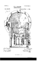
- Figure 1 is a perspective of the shinglesawing machine.
- Fig. 2 is a top plan of the machine with parts broken away. so as to better illustrate certain details.
- Fig. 3 is an under side perspective of one corner of the carriage.
- Fig. 4 is an end view of carriage-supporting track.
- Fig. 5 shows a face andside view of the rocking arm, and Fig. 5 a side view of one of the fingers which engage rack on the carriage.
- Fig. 6 is an elevation of part Fig; 7 isan elevation of de-.
- Fig. 8 is an end elevation of parts of the machine.
- Fig. 9 is an .end elevation, with parts omitted, of the tilt-actuating mechanism.
- Figs. 10 and 11 are detail elevations of ratchet-wheels, which may be used in connection with the tilt.
- This shingle-machine is of the same gen-. eral typeof hand-feed machines as described in Letters Patent to Willis J. Perkins, dated March 31, 1885, No. 314,603.
- arm g is pivoted to the part h of the frame and can rock on the pivot e in the direction of the movement of the carriage.
- Lugs g on this arm support the pivot f, which carries the fingers 0 0.
- These fingers or catches c c are drawn toward the bar 9 by springs 1;, attached to lugs or projections 0 and c on the fingers and on the arm, so that the fingers c 0 will be drawn by the springs into engagement with the rack-bar b.
- the ends of the teeth of the rack -'bar should be inclined, as shown, and the adjacent sides of the spring-fingers are also beveled or inclined, (see Fig. 2,) while the outer faces of these fingers are at a right angle to the line of movement of the carriage.
- the fingers c 0 have inwardly-projecting pins 0 0 Frame h has two inclines or cam-bearings h h
- Fig. 2 when the carriage is moved toward the saw the first tooth of rack 19 will engage finger o and swing said finger and its arm g in the direction of movement of the The pin c bearing on the incline gagement with the rack-teeth, and thecarriage will thencompiete its movement without further rocking the arm finger c sliding along the rack-teeth.
- the carriage a a has a x
- the arm g has a pawl t'
- the pawl i should be adj ustable on arm g, so as to have a different throw when desired;
- the ratchet -cam j is held from too easy rotation by friction-bar n, bearing on the outer or disk face of said ratchet, the friction being regulatedby nut n-.
- the ratchet-camj hasa race cam or groove :1, in which a roller bearing. This roller is is mounted on a swinging frame k, which is pivotally supported on part h of the machine-frame.
- the free end k of frame It has a hole through it, and rod 1 passes through this hole:
- the rod 1 may thus have a play in itsseat in frame k, which play will be regulated by set-nuts 1' 1
- the swing of frame 70 is more than enough to m ye the ion 1 longitudinally to" the greatest disfane needed to seen-are the tilt-table, and
- the tilt movement may be regulated by the lost motion between nuts 1 Z and frame k: (Seeniy patent, Nd. 23 6;62 0,of-January 11, 18811) tlliel jifiesfe er the fight-handshihglef point; til en the nut Z so as'te inalie qiii elzer engagement with endser frame It, vice versa: (see Fig. 9;) d
- Fig; il eeeotniilislies thispeeiiliarinetien tlie j? is preferably less than the dwell in the raceway. (See Fig. 7.) As carriage moves forward from left to right, pawl I drops over tooth f. In reverse motion of the carriage pawl I rotates the Ioilg distal'le' from tooth j to toothj The forward movement of carriagepawl I traverses the long distance, but falls short of dropping over tooth j a distance equal to 1 distance from point of tooth 7' to tooth j.
- Marry other-form's may eeiiee unfair-y; biit IOC the" abeveare alltradereqliifieliients liaveneveloiied smi e-sent.
- the tilt-table bearieg-eiiiteee p p is an mprove'riieht es pateht to eeitleesea; 1%. 298,737; May 20, 1884, said eei iee as therein shoi'vn net Being atiplie'able" re the ie-eminforth of tilt used by meeea menietll'ea et attaching rollers therein tleserineu beifig tilisetisreeleiy in graeiiee.
- p r is retitangiilar frame having double ewes-end e's'eiiee er relleisq senile ed on shitable'shaftsaitd having" nner-seeiings in each of the sides 1; 1') to diminish the space
- holt heafitig seiraee on the peribheryof tellers
- t ere by lesseeleg liability of the hi'lii dW bolts tippin I do'll'lil u thelin'eof sellers by alternatin this toll''rs on th journals; the ii fiitt'fi'il'g sll'lface is deemed; and teiideney to get eat ef alig'riliie'iit is lessened;
- the toner-sepstationtimep p is pivetelly attahd ill) the iildiihfin't tilt'sid 13 while it rests leesely on tilt side p theieby allowlllg it to slide thereon to eenipensate'fdrdreiv of eircular movement of tilt side ja
- the tilt sides 19 and p are moved by draw-bar m,
- the carriage therefore has two side pieces a a, preferably made of wood.
- Stationary dog r is bolted to them.
- the movable dog 'r' has sliding bearings on metal pieces or binding strips 8, Fig. 3, a recess 3 being cut in the carriage side a, forming the seat for slide bearing the dog 7'.
- the tiet connects the two ends of sides a a, and is bolted solid to sides a, a. Tiet is turned up on the ends, sleeve-bearings t, fastened thereto, forming j ourn al-seats for dogging-rod z.
- Sliding bearing '0 is formed partially out of the, dog-seat s, the piece 5' being turned down to present a bearing-face for slide-rail 0a m and completed by right-angle bearingy.
- Part of bearing g has an inwardlyextending projection 11/, which. fits into groove 00' on slide-railsc 0c. The carriage a a is thereby locked on the sliderail 0: 0c and cannot be thrown off the rail onto the saw.
- a further object of my improved carriage is to meet the wants of manufacturers that are making dimension shinglesthatis,shingles of uniform widths.
- the standards of shingles now adopted and manufactured extensively in certain sections of the United States are respectively four inches, five inches, and six and one-half inches. It is with present methods employed very difficult tocrosscut shingle-bolts from the log of exactlength. It is also a waste of time to saw shingles with one narrow bolt in the shingle-machine carriage at atime; thereforel have adapted th'is carriage to hold from one to three shinglebolts of varying lengths, as now about to be described.
- a-shingle-bolt having an irregular doggingsurface or a number of shingle-bolts 0t uneven length or dogging-surface are to be held in one carrier, carriage, or compartment the grasp of the dog or dogs on the bolts must be very firm and solid.
- the dogs must be able to support or carry the bolt or bolts or spalts thereof over an open space--such as the space between the end of the tilt-table and the edge of the saw or other. space where there is no supporting way for the bolt to ride on'and the weight of the bolt or the jar of the machine or other accidental causemust not loosen the hold of the dogs.
- the dogs must only loosen the bolts when they are expected to do so, if good results are desired.
- auxiliary dogging mechanism is applicable to shingle-sawing machines and block-sawing machines of. different construction, either reciprocating or rotary, and hence I do .not limit myself to the application of this part of my invention to this particular'form'of shingle-machine or for It must be understood that where be used at the other end of the block without departing from my invention. labor of handlingis proportionatelydecreased.
- one dog 7" is of usual or any approved construction, as with a series of holding-teeth arranged side by side and shown in ,line with each other and near one end of the carriage.
- the other dog r has a series of holders or biting-teeth r which in some measure partake of the movement of the main dog 1*, but have also an independent movement.
- Fig. 3 shows the dog-teeth or holders r as movable in bearings in the main dog 0".
- the movable dog 0 ismoved forward or back by any suitable train of mechanism common for the purpose. As shown, this general movement of the dog is effected by the following train of mechanism.
- the dog r is mounted on or carried by the supportrfl and the springs to are mounted on the support r which supports partake of the movement of and are preferably part of the main dog.
- a link 7* connects the dog r to the lever Z2 on the shaft. Consequently the rockin g of the shaft z throws the entire dog 0" forward or back, with a tendency to engage with the bolt or bolts, which may be between the dogs r/r';
- dog-teeth or holders 1' have a move ment independent of the dog r they will adjust themselves to' the ends of the bolt or bolts in the carriage, as many teeth or holders r engaging the end of a bolt or bolts'as the width of the bolt or bolts will warrant, andeven if the bolts are irregular in length or of irregular dogging-surface (within usual limits) the compound dog will adjust itself to engage and hold firmly the bolt or bolts in the carriage.
- the springs to have one bearing against the dogs or teeth r and the other against a piece which pal-takes of the move ment of and virtually forms part of the main dog 0".
- the spring-fingers constitute a clutch-trip, which makes engagement between the carriage and the tilt-operating train of mechanism, and'that said trip has this peculiarity of movement, that it is operative with thetirst movement of the carriage in either direction, and after it has been -in' operation long enough to actuate the tilt it becomes automaticallyinoperative, no matter what the movement of the carriage may be.”
- the trip has a variable relation to the carriage and operates antomatically, whether the carriage be reciprocated a long or short distance. This I find a very important feature of the machine. Thus, suppose the operator desires to saw shingles from a narrow bolt-say four inches wide the edge of the shingle-bolt is near the saw before the movement of the carriage begins.
- the combination with a reciprocating carriage, of a movable arm, a finger on said arm in position to engage the carriage, and a pawl extending from said arm and engaging with the tilt-operating ratchet, all in combination, substantially as described.
- a reciprocating carriage havinga rack thereon, a swinging arm 40 to engage said rack, a pawl connected to the arm, and a tilt-operating ratchet engaged by said pawl, all in combination, substantially as set forth.
- a reciprocating carriage a rack on said carriage, a swinging arm on the frame having fingers engaging said rack and having a pawl engaging the tilt-operatin g ratchet, and bearing-surfaces by which these fingers may be separately thrown out of engagement with the rack by the carriage movement, substantially as described.
- a reciprocating carriage a rack thereon, a pivoted arm on the carriage having a pawl operating on the tiltactuating ratchet, and a pair of spring-fingers, each finger having one inclined surface and one straight surface in position to engage with the rack, all the recited elements being combined substantially as described.
- a reciprocating carriage having projcction thereon, a movable catch outside the carriage in position to engage the said projection at the beginning of the carriage movement, and a tilt-actuating train connected to in the frame having spring-fingers in position r i blnation of the reciprocating carriage, an arm the catch, in combination, substantially as described.
- a reciprocating carriage moving on ways, a pair of catches outside the carriages and at the side of the ways in position to engage the carriage at the beginning of its movementin either direction, and a tilt-actuating train leading from said catches, the combination being and operating substantially as described.
- ashingle-machine the combination. of a reciprocating carriage having projections thereon, a finger in position to engage said carriage and actuate the tilt through a train of adj unctive connections, substantially asdescribed, and a rod under control of the operator in positionto hold said finger out of engagement, and thus render the tilt inoperative, substantially as described.
- the comriage has made a part of its movement, a pawl leading from said fingers, and a tilt-actuating cam engaged by said, pawl, all combined substantially as described.
- a reciprocating carriage a movable arm having fingers in position to engage said carriage, a pawl connected to said arm, interchangeable ratchetcams controlled by said pawl, and a tilt-rod actuated by one of said cams and connected to the tilt-table.
- a movable frame having a bearing-piece in said race, and a rod connected to the tilt, having adjustable engagement with said movable frame, whereby a lost motion is permitted to the frame which actuates the tilt-rod.
- a reciprocating carriage having projections thereon, a series of fingers mounted in the path of movement of said projections and having a movement in the general direction of the carriage and transversely thereof, a train connecting said fingers to the tilt, and bearing-surfaces in the line of movement of said fingers serving to disengage the same.
- one of said dogs having independent spring pressed teeth, substantially as described.
- said movable dog having sliding teeth or auxiliary dogs, each independently acted on by a .spring, substantially as stated.
- the com bination with two non metallic sides, a sta-' tionary dog forming end connections at one end between said sides, and a movable dog at opposite end, of a metallic tie forming end connection between side pieces, and having a journal-seat attached thereto for holding dog-operating rod.
- the saw a reciprocating carriage moving over the face thereof, a tilt-table and its operating-train, and a trip connected to said train in position to actuate the same at the beginning of the backward movement of the carriage from any part of its Way, in combinatiOn substantialIy as described.
- a bolt carrier having a holding-dog and a movable dog, said movable dog having separate and independently-movable teeth,-combined substantially as described.
- a bolt-carrier having a dog at one end of the bolt provided with a series of independently-movable teeth moving in bearings in the main dog and a retaining-dog at the other end of the shinglebolt, in combination, substantially as described.
- the movable carriage having a movable dog and mechanism for moving the same, a plurality of independent teeth carried by said dog, each tooth pressed by a spring which has a bearing on the main dog and on the tooth, and a separate holding-dog at the other end of the shingle-bolt, in combination, substantially as described.
- acarriage having a main dog and means for moving the same and auxiliary teeth in said dog, each tooth
Landscapes
- Life Sciences & Earth Sciences (AREA)
- Engineering & Computer Science (AREA)
- Wood Science & Technology (AREA)
- Forests & Forestry (AREA)
- Mechanical Engineering (AREA)
- Manufacturing & Machinery (AREA)
- Transmission Devices (AREA)
Description
(No Model.) 4 Sheets-Sheet 1.
W. J. PERKINS.
SHINGLE MACHINE.
No. 469,976. Patented Mar. 1, 1892.
0/2 om M Kay. 14% MM (No el) W" INS. SHINGLE MAC E.
4 Sheet et 2' Patented Mar. 1, 1892.
-" IIIIIII WAIXOLM f a I (No Model.) 4 Sheets-Sheet 3.
W. J. PERKINS. SHINGLE MACHINE.
No. 469,976. Patented Mar. 1, 1892.,
hm ARDLM 44/ MW 2. zfww WW4;
(No Model.) 4 SheetsSheet 4.
W. J. PERKINS. SYHINGLE MAGHINE.
No. 469,976. Pate nted Mar. 1, 1892 /$5555.. I 2 4% v fi Q/M r I "U ITED; STATES PATENT OFFICE.
WILLIS-J. PERKINS, OF GRAND RAPIDS, MICHIGAN.
SHINGLE MACHINE.
SPECIFICATION forming part of Letters Patent No. 469,976, dated March 1, 1892. Application filed November 5, 1888. Renewed June 20, 1891- Serial No. 396,895. (No model.)
4 siding at Grand Rapids, in the State of Michigan, have invented certain new and useful Improvementsin Shingle-Machines, of which the following is a specification, reference being had therein to the accompanying drawings.
This invention relates to shingle-sawing machines; and the object of the invention is of the frame.
tails hereinafter referred to.
.to improve the various parts of the machine.
The invention most particularly relates to im provements onhand-feed shingle-machines in the mechanism for operating the tilt-table of a shingle-machine and also the bolt-supporting surface of the tilt-table, also the boltcarrying carriage and the dogging mechanism of ashingle-machine. s
Figure 1 is a perspective of the shinglesawing machine. Fig. 2 is a top plan of the machine with parts broken away. so as to better illustrate certain details. Fig. 3 is an under side perspective of one corner of the carriage. Fig. 4 is an end view of carriage-supporting track. Fig. 5 shows a face andside view of the rocking arm, and Fig. 5 a side view of one of the fingers which engage rack on the carriage. Fig. 6 is an elevation of part Fig; 7 isan elevation of de-. Fig. 8 is an end elevation of parts of the machine. Fig. 9 is an .end elevation, with parts omitted, of the tilt-actuating mechanism. Figs. 10 and 11 are detail elevations of ratchet-wheels, which may be used in connection with the tilt.
This shingle-machine is of the same gen-. eral typeof hand-feed machines as described in Letters Patent to Willis J. Perkins, dated March 31, 1885, No. 314,603.
Thetilt-table used on this machine is fully described in patent to WVillis J. Perkins, No. 236,620, dated January 11, 1881, excepting the roller-bolt bearing-s11 rface and method of operating hereinafter described. Tilting mechanism has heretofore been applied to handfeed machines; but in all such devices with which I am familiar the carriag has to be brought backto aixed point before the tiltingmotion was completed, thereby requiring extra exertionofthe operator and consequent lossoftime. Inthle following-described movement for operating the tilt the above objection is-overcome. H r 1 I .on which the pins 0 c impinge.
carriage. 71 will gradually lift the finger 0 out of enrack-bar b attached to one side. Two rocking fingers c o are supported on the frame in a manner which will now be described. An
arm g is pivoted to the part h of the frame and can rock on the pivot e in the direction of the movement of the carriage. Lugs g on this arm support the pivot f, which carries the fingers 0 0. These fingers or catches c c are drawn toward the bar 9 by springs 1;, attached to lugs or projections 0 and c on the fingers and on the arm, so that the fingers c 0 will be drawn by the springs into engagement with the rack-bar b. The ends of the teeth of the rack -'bar should be inclined, as shown, and the adjacent sides of the spring-fingers are also beveled or inclined, (see Fig. 2,) while the outer faces of these fingers are at a right angle to the line of movement of the carriage. Consequently one of the fingers will, oppose a resistance to the movement of the carriage in one direction and theother in the other direction when in engagement, but both may rock out of engage ment with the teeth of the carriage. The fingers c 0 have inwardly-projecting pins 0 0 Frame h has two inclines or cam-bearings h h Now, referring to Fig. 2, when the carriage is moved toward the saw the first tooth of rack 19 will engage finger o and swing said finger and its arm g in the direction of movement of the The pin c bearing on the incline gagement with the rack-teeth, and thecarriage will thencompiete its movement without further rocking the arm finger c sliding along the rack-teeth. On a reverse movement of carriage and rack b the finger 0' will be engaged by the rack-teeth until its pin 0 bearing on the incline h, is lifted free of the rack-teeth. Thus the reciprocation of the carriage through a long path will swing the arm g buta short distance, determined by the cam-surfaces h 7L2. pivoted thereto, the free end of the pawl engaging the teeth of a ratchet-cam j, which is journaled to a stud or bar h of the frame.
The carriage a a has a x The arm g has a pawl t' The pawl i should be adj ustable on arm g, so as to have a different throw when desired; The ratchet -cam j is held from too easy rotation by friction-bar n, bearing on the outer or disk face of said ratchet, the friction being regulatedby nut n-. The ratchet-camjhasa race cam or groove :1, in which a roller bearing. This roller is is mounted on a swinging frame k, which is pivotally supported on part h of the machine-frame. The free end k of frame It has a hole through it, and rod 1 passes through this hole: The rod 1 may thus have a play in itsseat in frame k, which play will be regulated by set-nuts 1' 1 The swing of frame 70 is more than enough to m ye the ion 1 longitudinally to" the greatest disfane needed to seen-are the tilt-table, and
thusthe tilt movement may be regulated by the lost motion between nuts 1 Z and frame k: (Seeniy patent, Nd. 23 6;62 0,of-January 11, 18811) tlliel jifiesfe er the fight-handshihglef point; til en the nut Z so as'te inalie qiii elzer engagement with endser frame It, vice versa: (see Fig. 9;) d
As it is rich always'desirable te tilt the tiltte-lile after sawin a shingle, tirefolltiwi'h1e, riie'blih nisiii; is shown for throwing the tiltaetuitiiig lingers; out of epeiatieii, so that whentilte'tl in either d ireendn the tilt-table will fie inaiii uinlismi-lied. A reeksnaf't e at deer are maeliin beers drank or ee- "e' loated inside of the s ngers cc. A-1tVr 0 olt't-he 'r'o'cliz-shaftio isconnecfied by dra fo d with liberating lever-er nannies", Wilfl'l "is lo'eated en the merit Name i'wvithlh reahh of the hand of the operator: When the i eek eliar e thrnetl by meviiigthe their; tire era-in: o'r eeeent ie o is turned to engage the rack b; The tilet able will then rein n unmoved duiir'ig the i ee'iiifdeatien of tliey eai-r iagel It will be undeis'tdod that other equivalent mechanism" meylieeinpleyeu aeledniplish wholly by the 'foiih of dams and rat'ciliet -wiiel as follows; Cam 5% Fig.10, is me-tie withe reee'wa similei to elite eneam j;je{ eept the dwell is longer,- the variation otherwise bein confined to the spairig of the 'i-ateh't teeth; The long distanee from tooth j" to tooth j is the same as travel given to of eerne left; then one butt; and se on. Fig; il eeeotniilislies thispeeiiliarinetien tlie j? is preferably less than the dwell in the raceway. (See Fig. 7.) As carriage moves forward from left to right, pawl I drops over tooth f. In reverse motion of the carriage pawl I rotates the Ioilg distal'le' from tooth j to toothj The forward movement of carriagepawl I traverses the long distance, but falls short of dropping over tooth j a distance equal to 1 distance from point of tooth 7' to tooth j. On reverse movement pawl I rides over back of tooth j until it engages with tooth j, when it pat'tially rotates cam-wheel a distance equal to distance between tooth j and toothj thei-ebfv f'eqiiit'ihg' two movements ete lfdt ohechatlg'e' er tilt; m
stealer glee. Tlie'first "cu't s witlrpemwt the left;
seeend e'iitwitli biifiet the left; third eat with point atl'e'l t. The next beard nltlst stain with point at left weeiile 'eut right. There ferethe earnwvheel -ltl'list nieke twojioi'nt's at Cam-wheelie ratchet being s eeed seflhet riy ineeiie er altel-date long teeth it takes two filoveiiifits el eerrieige to rotate a lift of racewa as tiltisc'tildedheifetofote e11 amj".
Marry other-form's may eeiieeessai-y; biit IOC the" abeveare alltradereqliifieliients liaveneveloiied smi e-sent. N
The tilt-table bearieg-eiiiteee p p is an mprove'riieht es pateht to eeitleesea; 1%. 298,737; May 20, 1884, said eei iee as therein shoi'vn net Being atiplie'able" re the ie-eminforth of tilt used by meeea menietll'ea et attaching rollers therein tleserineu beifig tilisetisreeleiy in graeiiee.
p y) p r is retitangiilar frame having double ewes-end e's'eiiee er relleisq senile ed on shitable'shaftsaitd having" nner-seeiings in each of the sides 1; 1') to diminish the space Between the holt=heafitig seiraee on the peribheryof tellers, t ereby lesseeleg liability of the hi'lii dW bolts tippin I do'll'lil u thelin'eof sellers by alternatin this toll''rs on th journals; the ii fiitt'fi'il'g sll'lface is deemed; and teiideney to get eat ef alig'riliie'iit is lessened;
p p ai'ee'iessi-bars ebiiiieetiii the eides p. The toner-sepserungtimep p is pivetelly attahd ill) the iildiihfin't tilt'sid 13 while it rests leesely on tilt side p theieby allowlllg it to slide thereon to eenipensate'fdrdreiv of eircular movement of tilt side ja The tilt sides 19 and p are moved by draw-bar m,
which is connected to draw-barl, and the lowermost position of either end of the tilt may be determined by set-screws, as in my patent referred.
'In hand-feed machines the operator has to propel the carriage back and forth by sheer force of muscle, therefore by lightening it the The carriage therefore has two side pieces a a, preferably made of wood. Stationary dog r is bolted to them. The movable dog 'r' has sliding bearings on metal pieces or binding strips 8, Fig. 3, a recess 3 being cut in the carriage side a, forming the seat for slide bearing the dog 7'. The tiet connects the two ends of sides a a, and is bolted solid to sides a, a. Tiet is turned up on the ends, sleeve-bearings t, fastened thereto, forming j ourn al-seats for dogging-rod z. Sliding bearing '0 is formed partially out of the, dog-seat s, the piece 5' being turned down to present a bearing-face for slide-rail 0a m and completed by right-angle bearingy. Part of bearing g has an inwardlyextending projection 11/, which. fits into groove 00' on slide-railsc 0c. The carriage a a is thereby locked on the sliderail 0: 0c and cannot be thrown off the rail onto the saw.
A further object of my improved carriage is to meet the wants of manufacturers that are making dimension shinglesthatis,shingles of uniform widths. The standards of shingles now adopted and manufactured extensively in certain sections of the United States are respectively four inches, five inches, and six and one-half inches. It is with present methods employed very difficult tocrosscut shingle-bolts from the log of exactlength. It is also a waste of time to saw shingles with one narrow bolt in the shingle-machine carriage at atime; thereforel have adapted th'is carriage to hold from one to three shinglebolts of varying lengths, as now about to be described. a-shingle-bolt having an irregular doggingsurface or a number of shingle-bolts 0t uneven length or dogging-surface are to be held in one carrier, carriage, or compartment the grasp of the dog or dogs on the bolts must be very firm and solid. The dogs must be able to support or carry the bolt or bolts or spalts thereof over an open space--such as the space between the end of the tilt-table and the edge of the saw or other. space where there is no supporting way for the bolt to ride on'and the weight of the bolt or the jar of the machine or other accidental causemust not loosen the hold of the dogs. The dogs must only loosen the bolts when they are expected to do so, if good results are desired.
The principle of the auxiliary dogging mechanism is applicable to shingle-sawing machines and block-sawing machines of. different construction, either reciprocating or rotary, and hence I do .not limit myself to the application of this part of my invention to this particular'form'of shingle-machine or for It must be understood that where be used at the other end of the block without departing from my invention. labor of handlingis proportionatelydecreased.
Referring to Fig. 2, and especially tothe .detail, Fig. 3, one dog 7" is of usual or any approved construction, as with a series of holding-teeth arranged side by side and shown in ,line with each other and near one end of the carriage. The other dog r has a series of holders or biting-teeth r which in some measure partake of the movement of the main dog 1*, but have also an independent movement.
Fig. 3 shows the dog-teeth or holders r as movable in bearings in the main dog 0". A spring to, connected to some part of the main dog, acts on each tooth or holder 7' to press said tooth or holder forward, the dog r sliding in ways in the body of the main dog 0". The movable dog 0 ismoved forward or back by any suitable train of mechanism common for the purpose. As shown, this general movement of the dog is effected by the following train of mechanism. The dog r is mounted on or carried by the supportrfl and the springs to are mounted on the support r which supports partake of the movement of and are preferably part of the main dog. A link 7* connects the dog r to the lever Z2 on the shaft. Consequently the rockin g of the shaft z throws the entire dog 0" forward or back, with a tendency to engage with the bolt or bolts, which may be between the dogs r/r';
but as dog-teeth or holders 1' have a move ment independent of the dog r they will adjust themselves to' the ends of the bolt or bolts in the carriage, as many teeth or holders r engaging the end of a bolt or bolts'as the width of the bolt or bolts will warrant, andeven if the bolts are irregular in length or of irregular dogging-surface (within usual limits) the compound dog will adjust itself to engage and hold firmly the bolt or bolts in the carriage. The springs to have one bearing against the dogs or teeth r and the other against a piece which pal-takes of the move ment of and virtually forms part of the main dog 0".
High bolts are apt to tip when being sawed. To prevent this, I have placed the guides or gages z .2 a .2 on front side of carriage, against which the bolt may be held by the operator while sawing, he employing one hand, as a rule, to handle the carriage with.
It will be understood that the spring-fingers constitute a clutch-trip, which makes engagement between the carriage and the tilt-operating train of mechanism, and'that said trip has this peculiarity of movement, that it is operative with thetirst movement of the carriage in either direction, and after it has been -in' operation long enough to actuate the tilt it becomes automaticallyinoperative, no matter what the movement of the carriage may be."
It will thus appear that the trip has a variable relation to the carriage and operates antomatically, whether the carriage be reciprocated a long or short distance. This I find a very important feature of the machine. Thus, suppose the operator desires to saw shingles from a narrow bolt-say four inches wide the edge of the shingle-bolt is near the saw before the movement of the carriage begins.
[O The operator presses the carriage and bolt toward the saw, and,as soon as the shingle is sawed from the bolt, reverses the carriage. The clutch will be actuated to move the tilt precisely as if the carriage had made a long travel-as for an eight or twelve inch shingle- -boltor a number of narrow bolts. Thus the operator is not compelled to make a full reciprocation of the carriage in order to actuate the tilt, as in all other machines with 1. In a shingle-sawing machine,the combination, with a reciprocating carriage, of a movable arm, a finger on said arm in position to engage the carriage, and a pawl extending from said arm and engaging with the tilt-operating ratchet, all in combination, substantially as described.
2. In a shingle-machine, a reciprocating carriage havinga rack thereon, a swinging arm 40 to engage said rack, a pawl connected to the arm, and a tilt-operating ratchet engaged by said pawl, all in combination, substantially as set forth.
3. In a-shingle-machine, a reciprocating carriage, a rack on said carriage, a swinging arm on the frame having fingers engaging said rack and having a pawl engaging the tilt-operatin g ratchet, and bearing-surfaces by which these fingers may be separately thrown out of engagement with the rack by the carriage movement, substantially as described.
4. In a shingle-machine, a reciprocating carriage, a rack thereon, a pivoted arm on the carriage having a pawl operating on the tiltactuating ratchet, and a pair of spring-fingers, each finger having one inclined surface and one straight surface in position to engage with the rack, all the recited elements being combined substantially as described.
5. In a shingle-sawing machine, the combination of a reciprocating carriage having projcction thereon, a movable catch outside the carriage in position to engage the said projection at the beginning of the carriage movement, and a tilt-actuating train connected to in the frame having spring-fingers in position r i blnation of the reciprocating carriage, an arm the catch, in combination, substantially as described.
6. In a shin gle-machine, a reciprocating carriage moving on ways, a pair of catches outside the carriages and at the side of the ways in position to engage the carriage at the beginning of its movementin either direction, and a tilt-actuating train leading from said catches, the combination being and operating substantially as described.
7 In a shin gle-machine, a moving carriage, a catch outside the carriage connected to the tilt-actuating train in position to engage said carriage at the beginning of its movement in either direction, and. detaching surfaces to disengage said catch after it has moved a limited distance with the carriage, all combined substantially as stated. 7
8. In a shin gle machine, the combination of a reciprocating carriage having projections thereon, movable fingers supported by the frame-in position to engage said projections,
inclines connectedto theframe. in position to disengage said. fingers from the carriagc during the carriage movement, a pawl connected i to said fingers so as to partake of the carriage movement during the engagement of the fingers therewith, and a tilt-actuating .pawl engaged by said ratchet, all substantially asdescribed. i
9. In ashingle-machine, the combination. of a reciprocating carriage having projections thereon, a finger in position to engage said carriage and actuate the tilt through a train of adj unctive connections, substantially asdescribed, and a rod under control of the operator in positionto hold said finger out of engagement, and thus render the tilt inoperative, substantially as described.
10. In a shingle-sawing machine, the comriage has made a part of its movement, a pawl leading from said fingers, and a tilt-actuating cam engaged by said, pawl, all combined substantially as described.
11. In a shingle-machine,-a reciprocating carriage, a movable arm having fingers in position to engage said carriage, a pawl connected to said arm, interchangeable ratchetcams controlled by said pawl, and a tilt-rod actuated by one of said cams and connected to the tilt-table.
12. The combination with the vibrating arm and its pawl, of a ratchet having uneven- 1y spaced teeth, a cam connected to said ratchet, and a rod whereby the tilt is actuated by said cam, substantially as stated.
13. In combination with the race-cam and its driving mechanism, a movable frame having a bearing-piece in said race, and a rod connected to the tilt, having adjustable engagement with said movable frame, whereby a lost motion is permitted to the frame which actuates the tilt-rod.
14. The combination, with the race-cam and its driving mechanism, of a bearing-wheel in said cam-race, a rod passing loosely through the journal-piece of the bearing-wheel and connected to the tilt, and adjustable stops on the rod, whereby its movement in either direction may be governed by the bearingwheels in the cam-race, substantially as described.
15. In a shingle-machine, the combination of the carriage-ways, a carriage moving thereon to a greater or less distance, as desired, and a tilt-actuating clutch engaging said carriage at the beginning'of its movement in either'direction.
16. In a shingle-machine, a reciprocating carriage having projections thereon, a series of fingers mounted in the path of movement of said projections and having a movement in the general direction of the carriage and transversely thereof, a train connecting said fingers to the tilt, and bearing-surfaces in the line of movement of said fingers serving to disengage the same.
17. In a shingle-sawing machine, the combination, with the reciprocating carriage, of
a vertical block-supporting gage on the carriage and extending above the same at the side next the saw.
18. In a shingle-machine, the combination, with the carriage and block-supporting table, of a plural series of anti-friction wheels at one side of the table, said wheels overlapping each other, substantially as shown.
19. In a shingle-machine carriage, the combination of a stationary dog at one end of the carriage and a movable dog at the other end,
one of said dogs having independent spring pressed teeth, substantially as described.
20. In a shingle-machine carriage, the combination of a stationary dog at one end of the carriage and a movable dog at the other end,
said movable dog having sliding teeth or auxiliary dogs, each independently acted on by a .spring, substantially as stated.
21. In a shingle-machine carriage, the com bination, with two non metallic sides, a sta-' tionary dog forming end connections at one end between said sides, and a movable dog at opposite end, of a metallic tie forming end connection between side pieces, and having a journal-seat attached thereto for holding dog-operating rod.
than a complete reciprocation.
24'. The saw, a reciprocating carriage moving over the face thereof, a tilt-table and its operating-train, and a trip connected to said train in position to actuate the same at the beginning of the backward movement of the carriage from any part of its Way, in combinatiOn substantialIy as described.
25. In a shingle machine, a bolt carrier having a holding-dog and a movable dog, said movable dog having separate and independently-movable teeth,-combined substantially as described.
' 26. In a shingle-machine, a bolt-carrierhaving a dog at one end of the bolt provided with a series of independently-movable teeth moving in bearings in the main dog and a retaining-dog at the other end of the shinglebolt, in combination, substantially as described.
27. In a shingle-machine, the movable carriage having a movable dog and mechanism for moving the same, a plurality of independent teeth carried by said dog, each tooth pressed by a spring which has a bearing on the main dog and on the tooth, and a separate holding-dog at the other end of the shingle-bolt, in combination, substantially as described.
28. In a shingle-machine, acarriage having a main dog and means for moving the same and auxiliary teeth in said dog, each tooth
Publications (1)
| Publication Number | Publication Date |
|---|---|
| US469976A true US469976A (en) | 1892-03-01 |
Family
ID=2538836
Family Applications (1)
| Application Number | Title | Priority Date | Filing Date |
|---|---|---|---|
| US469976D Expired - Lifetime US469976A (en) | Shingle-machine |
Country Status (1)
| Country | Link |
|---|---|
| US (1) | US469976A (en) |
-
0
- US US469976D patent/US469976A/en not_active Expired - Lifetime
Similar Documents
| Publication | Publication Date | Title |
|---|---|---|
| US1093680A (en) | Machine for making railway-ties. | |
| US463234A (en) | Shingle-sawing machine | |
| US511573A (en) | wilkinson | |
| US477832A (en) | Spool-rdughing machine | |
| US404827A (en) | Machine for sawing shingles | |
| US752055A (en) | Shingle-machine | |
| US440388A (en) | Saw-mill | |
| US561278A (en) | Shingle-machine | |
| US6443A (en) | Machinery eos | |
| US261804A (en) | brooks | |
| US5898A (en) | Sawmill | |
| US333244A (en) | Set-works for saw-mills | |
| US15749A (en) | Shingle-machine | |
| US245312A (en) | Log rolling and sorting machine | |
| US115492A (en) | Improvement in head-blocks | |
| US1067928A (en) | Mortising-machine. | |
| US495405A (en) | The nprbis peters co | |
| US507020A (en) | Half to frank g | |
| US547796A (en) | Band-saw resawing-machine | |
| US505482A (en) | Machine for sawing logs | |
| US915198A (en) | Set-works for sawmills. | |
| US271747A (en) | smith ge | |
| US1240393A (en) | Machine for forming openings in window-stiles. | |
| US660931A (en) | Shingle-sawing machine. | |
| US313531A (en) | Saw-mill head-block |