US4694715A - Slicing device for bread or the like - Google Patents
Slicing device for bread or the like Download PDFInfo
- Publication number
- US4694715A US4694715A US06/904,872 US90487286A US4694715A US 4694715 A US4694715 A US 4694715A US 90487286 A US90487286 A US 90487286A US 4694715 A US4694715 A US 4694715A
- Authority
- US
- United States
- Prior art keywords
- bands
- slicer
- drums
- drum
- machine according
- Prior art date
- Legal status (The legal status is an assumption and is not a legal conclusion. Google has not performed a legal analysis and makes no representation as to the accuracy of the status listed.)
- Expired - Lifetime
Links
Images


Classifications
-
- B—PERFORMING OPERATIONS; TRANSPORTING
- B26—HAND CUTTING TOOLS; CUTTING; SEVERING
- B26D—CUTTING; DETAILS COMMON TO MACHINES FOR PERFORATING, PUNCHING, CUTTING-OUT, STAMPING-OUT OR SEVERING
- B26D1/00—Cutting through work characterised by the nature or movement of the cutting member or particular materials not otherwise provided for; Apparatus or machines therefor; Cutting members therefor
- B26D1/01—Cutting through work characterised by the nature or movement of the cutting member or particular materials not otherwise provided for; Apparatus or machines therefor; Cutting members therefor involving a cutting member which does not travel with the work
- B26D1/46—Cutting through work characterised by the nature or movement of the cutting member or particular materials not otherwise provided for; Apparatus or machines therefor; Cutting members therefor involving a cutting member which does not travel with the work having an endless band-knife or the like
- B26D1/48—Cutting through work characterised by the nature or movement of the cutting member or particular materials not otherwise provided for; Apparatus or machines therefor; Cutting members therefor involving a cutting member which does not travel with the work having an endless band-knife or the like with tensioning means
-
- B—PERFORMING OPERATIONS; TRANSPORTING
- B26—HAND CUTTING TOOLS; CUTTING; SEVERING
- B26D—CUTTING; DETAILS COMMON TO MACHINES FOR PERFORATING, PUNCHING, CUTTING-OUT, STAMPING-OUT OR SEVERING
- B26D1/00—Cutting through work characterised by the nature or movement of the cutting member or particular materials not otherwise provided for; Apparatus or machines therefor; Cutting members therefor
- B26D1/01—Cutting through work characterised by the nature or movement of the cutting member or particular materials not otherwise provided for; Apparatus or machines therefor; Cutting members therefor involving a cutting member which does not travel with the work
- B26D1/46—Cutting through work characterised by the nature or movement of the cutting member or particular materials not otherwise provided for; Apparatus or machines therefor; Cutting members therefor involving a cutting member which does not travel with the work having an endless band-knife or the like
- B26D1/50—Cutting through work characterised by the nature or movement of the cutting member or particular materials not otherwise provided for; Apparatus or machines therefor; Cutting members therefor involving a cutting member which does not travel with the work having an endless band-knife or the like with a plurality of band-knives or the like
-
- Y—GENERAL TAGGING OF NEW TECHNOLOGICAL DEVELOPMENTS; GENERAL TAGGING OF CROSS-SECTIONAL TECHNOLOGIES SPANNING OVER SEVERAL SECTIONS OF THE IPC; TECHNICAL SUBJECTS COVERED BY FORMER USPC CROSS-REFERENCE ART COLLECTIONS [XRACs] AND DIGESTS
- Y10—TECHNICAL SUBJECTS COVERED BY FORMER USPC
- Y10T—TECHNICAL SUBJECTS COVERED BY FORMER US CLASSIFICATION
- Y10T83/00—Cutting
- Y10T83/141—With means to monitor and control operation [e.g., self-regulating means]
-
- Y—GENERAL TAGGING OF NEW TECHNOLOGICAL DEVELOPMENTS; GENERAL TAGGING OF CROSS-SECTIONAL TECHNOLOGIES SPANNING OVER SEVERAL SECTIONS OF THE IPC; TECHNICAL SUBJECTS COVERED BY FORMER USPC CROSS-REFERENCE ART COLLECTIONS [XRACs] AND DIGESTS
- Y10—TECHNICAL SUBJECTS COVERED BY FORMER USPC
- Y10T—TECHNICAL SUBJECTS COVERED BY FORMER US CLASSIFICATION
- Y10T83/00—Cutting
- Y10T83/647—With means to convey work relative to tool station
- Y10T83/6584—Cut made parallel to direction of and during work movement
- Y10T83/6633—By work moving flexible chain or conveyor
-
- Y—GENERAL TAGGING OF NEW TECHNOLOGICAL DEVELOPMENTS; GENERAL TAGGING OF CROSS-SECTIONAL TECHNOLOGIES SPANNING OVER SEVERAL SECTIONS OF THE IPC; TECHNICAL SUBJECTS COVERED BY FORMER USPC CROSS-REFERENCE ART COLLECTIONS [XRACs] AND DIGESTS
- Y10—TECHNICAL SUBJECTS COVERED BY FORMER USPC
- Y10T—TECHNICAL SUBJECTS COVERED BY FORMER US CLASSIFICATION
- Y10T83/00—Cutting
- Y10T83/707—By endless band or chain knife
- Y10T83/7158—Including plural cutting zones
- Y10T83/7183—Including "figure-8" band
-
- Y—GENERAL TAGGING OF NEW TECHNOLOGICAL DEVELOPMENTS; GENERAL TAGGING OF CROSS-SECTIONAL TECHNOLOGIES SPANNING OVER SEVERAL SECTIONS OF THE IPC; TECHNICAL SUBJECTS COVERED BY FORMER USPC CROSS-REFERENCE ART COLLECTIONS [XRACs] AND DIGESTS
- Y10—TECHNICAL SUBJECTS COVERED BY FORMER USPC
- Y10T—TECHNICAL SUBJECTS COVERED BY FORMER US CLASSIFICATION
- Y10T83/00—Cutting
- Y10T83/707—By endless band or chain knife
- Y10T83/7226—With means to guard the tension
- Y10T83/7239—With means to vary distance between pulley or sprocket axes
- Y10T83/7251—Including means to yieldably bias pulley
- Y10T83/7258—By fluid means
Definitions
- the invention relates to a slicing device for breads or the like, comprising a plurality of endless slicer bands, which extend substantially parallel to each other and which are passed over drums, and tensioning means for biasing the slicer bands engage the slicer bands.
- the slicing device is characterized in that the tensioning means are automatically adjustable under control of a control device, in such a way that a substantially constant tension of the slicer bands is maintained.
- At least one of the drums is automatically adjustable and acts as tensioning means.
- the drums serve not only for driving the slicer bands, but also for maintaining a constant tension therein.
- the adjustable drum is supported by means of at least one adjustable cylinder-plunger assembly, while in a very important embodiment of the slicing device according to the invention a cylinder-plunger assembly is mounted on either side of the adjustable drum, the cylinder-plunger assemblies acting as adjustable supports for the adjustable drum and being operable independently of each other.
- each drum is connected to each other by a bracket, which is mounted to a stationary frame on one side of the respective drum, both brackets extending in between both parts of the slicer bands.
- the displacement of the adjustable drum with respect to the stationary frame can be measured or scanned, and a switch contact being provided, which can be activated by an inward displacement of the adjustable drum along a predetermined distance.
- an optical signal, a slicer band grinder and/or a slicer band lubricating device may be switched on, while according to the invention it is also proposed to change the relative supply speed of the loafs or the like.
- the slicer bands lie with their flat sides against the drums, and are twisted substantially 90° in respect thereof in a central area between the drums by means of guides which consist of cylindrical pins, the longitudinal axis thereof extending substantially perpendicular to the axes of rotation of the drums, it is advantageously when the pins consist of a steel, of which the smooth outer surface is treated by nitriding.
- a slicing device having a feeding table for the bread or the like on which the loafs are guided through the slicer bands is according to the invention characterized in that the inclination of the upper face of the feeding table is adjustable with respect to the slicer bands as seen transverse to the conveying direction of the loafs.
- FIG. 1 is a perspective view of an embodiment of the slicing device according to the invention.
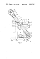
- FIG. 2 is an enlarged side view of the slicing device of FIG. 1 wherein a cover is omitted for the sake of clarity.
- FIG. 3 is a front view of the slicing device of FIG. 2.
- FIG. 4 is a schematic view of a modified embodiment of the slicing device according to the invention.
- the drawing shows an embodiment of a slicing device, which is used for slicing bread.
- This slicing device comprises a stationary frame generally indicated with reference numeral 1.
- the stationary frame 1 In the operative position of the slicing device the stationary frame 1 is enclosed by a cover 2 (FIG. 1), such that the movable parts of the device are entirely guarded.
- the cap 2 is constructed so as to be divisible vertically into two parts, a part 3 of the cover 2 may be loosened and may be driven away by means of a carriage provided with wheels (not shown). In this way all parts of the slicing device can be easily reached.
- the slicing device has a feeding table 4, onto which the loafs are conveyed in the direction of the arrow P into the slicing device by means of a feed arrangement.
- the feed arrangement comprises two endless conveyor belts 7, one at either side of the feeding table 4 and each thereof being passed over upright rolls 6, the endless conveyor belts 7 being adapted to engage the ends of the loafs.
- the driving of the feed arrangement can for instance be effected by means of an electric motor 32, which drives the axis of one of the rolls 6 of each conveyor belt 7 through a gear mechanism 33 (see FIG. 4).
- the slicing device comprises a plurality of endless slicer bands 10 which are passed over a lower drum 8 and an upper drum 9 and which extend substantially parallel to each other.
- the drawing illustrates only a few of such slicer bands 10, while it has to be understood that in fact a greater amount of slicer bands 10 are passed side by side over the drums 8 and 9.
- the slicer bands 10 are provided with saw teeth at one of their sharp edges for slicing the loafs.
- the lower drum 8 is mounted on an axle 11, which is rotatably supported by bearings 12 at either side of the drum 8.
- the bearings 12 are connected to each other by a bracket 13, which is rigidly connected to the stationary frame 1 on one end.
- a pulley 14 is provided, over which V-belts 15 pass, which can be driven by an electric motor 16.
- the upper drum 9 is rotatably mounted on an axle 17, which is non-rotatably mounted in guiding blocks 18, yet may be slid up and down in the direction of the connecting line between the axes of rotation of both drums 8 and 9.
- Both ends of the axle 17 are movably supported by the upper end of a rod 19 forming part of the plunger of a cylinder-plunger assembly 20, which is connected to the respective guiding block 18.
- By adjusting the cylinder-plunger assemblies 20 the ends of the axle 17 move in their respective guiding blocks 18.
- Both cylinder-plunger assemblies 20, which may be of a hydraulic or pneumatic construction, are operated independently of each other, so that the distance between the lower drum 8 and the upper drum 9 as well as the parallelism of drums 8 and 9 can be controlled.
- control circuit which controls the magnitude of the displacement of the plunger of the cylinder-plunger assemblies 20 as a function of the load on the upper drum 9 and a balancing circuit which causes the displacements to be equal at both cylinder-plunger assemblies independent of the load, so that the parallelism of the drums 8 and 9 is maintained.
- the upper drum 9 can be held in a parallel position by an independent control of the cylinder-plunger assemblies in case of an asymmetrical load of the slicer bands onto the upper drum 9.
- the height of the upper drum 9 will also change when the force exerted by the loafs onto the slicer bands 10 varies. This force will increase for instance when at a constant conveying speed of the loafs the slicing capacity of the slicer bands 10 decreases as a result of a blunting of the saw teeth.
- a switch which is not shown, can be activated when the upper drum 9 is displaced along a predetermined distance in the direction of the lower drum 8. By activating the switch it is for instance possible to give an optical signal in order to warn that the slicer bands 10 have become too blunt.
- the switch causes an integrated slicer band grinder, or a slicer band lubricating device respectively to be switched on and/or the conveying speed of the loafs to be slowed down.
- Such signalling or controlling respectively not only improves the control convenience of the slicing device, but can also prevent a rupture of the slicer bands at inconvenient moments.
- Both guiding blocks 18 are connected to each other by a bracket 21, which is connected to the stationary frame 1 on the same side as the bracket 13 is.
- the brackets 13 and 21 have such a configuration and extend in such a way in between both parts 10' and 10" of the slicer bands 10, that it is possible to remove the slicer bands 10 of the drum 8 and 9 and to install them again without having the drums 8 and 9 dismantled.
- Each slicer band 10 is passed over the drums 8 and 9 in such a way, that a leading part 10' and a return part 10" cross each other between the drums 8 and 9.
- the slicer bands 10 are twisted 90° with respect to their position on the drums 8 and 9, in such manner that the saw teeth of the parts 10' and 10" are directed in the same direction.
- the slicing device is provided with guide pins 22, which are mounted in two groups below and above the crossing point of the slicer band part 10' and 10" in holders 23, which are located behind the slicer bands 10 as seen in the conveying direction of the loafs.
- the guide pins 22 extend parallel to the conveying direction of the loafs and are positioned in such a way that each pair of slicer band parts 10' and 10" engages one of the guide pins 12 at two opposite points of the outer circumference thereof.
- the guide pins 22 of each group are positioned in staggered relation to each other such that the longitudinal axes of the guide pins 22 located at both sides of one of the slicer bands 10 are spaced from each other in the longitudinal direction of the slicer bands 10.
- the guide pins 22 are spaced from each other over such a distance that the slicer bands 10, which are twisted, can just pass between two adjacent guide pins 22. In this way the slice thickness of the loafs is determined by the outer diameter of the guide pins 22.
- the holders 23 provided with the guide pins 22 are pivotable about a horizontal axle 24, and an operating mechanism 25 engages the respective holder 23, in order to operate said holder 23 with its guide pins 22 to pivot about the horizontal axle 24. Consequently it is possible to remove the guide pins 22 from in between the slicer bands 10, so that the slicer bands 10 can be removed and installed without being hindered by the guide pins 22.
- the guide pins 22 preferably consists of a steel, which is hardened by means of nitriding. This is a heat treatment wherein the pins remain in an ammonia bath for 30 hours at a temperature of 500° C. In this way the steel becomes hard and ductile, and it also obtains lubricating qualities.
- Both congruent sharp angles between the slicer band parts 10' and 10" determine the so-called band distance, which is defined by the distance between both slicer band parts 10' and 10" at the upper or lower sides of the loafs when measured in the conveying direction of the loafs.
- This band distance must be less than 30 mm, because it has proved that in that case high or irregular formed loafs can be prevented from falling.
- the band distance is determined by the diameter ratio of the drums 8 and 9, the distance between the center lines of the drums 8 and 9 and the height of the point of intersection between slicer band parts 10' and 10" with respect to the loafs.
- the angle of the center line of the slicer bands 10, e.g. of the connecting line between the axes of rotation of the drums 8 and 9, with respect to the upper face of the bread feeding table 4 and therefore with respect to the supplied loafs substantially influences the friction forces exerted on the loafs by the slicer bands 10 during the slicing operation.
- These friction forces determine not only the calmness of the loafs in the slicer bands 10 (determining the uniformity of the slice thickness), but also the magnitude of the forwardly directed resultant of these friction forces (determining the required conveying pressure on the loafs).
- the most favourable position of the loafs with respect to the slicer bands 10 depends on the dimensions of the loafs.
- the most favourable height of the point of intersection of the slicer bands 10 with respect to the feeding table 4 also depends on the dimensions of the loafs.
- the feeding table 4 may be of an adjustable construction.
- FIG. 4 very schematically shows an embodiment of the slicing device, wherein the adjustment of the bread feeding table 4 has been realized.
- the feeding table 4 is connected pivotally about a horizontal transverse shaft 26 to the stationary frame 1 at its side facing away from the slicer bands 10.
- the angular rotation of the bread feeding table 4 not only the angle between the upper face of the feeding table 4 and the slicer bands 10 changes but also the difference in level between this upper face and the point of intersection of the slicer bands 10 varies. In this way the slicing operation can be optimized for each type of bread by adjusting the feeding table 4.
- FIG. 4 further shows that a guide pin unit 28 is carried by the bread feeding table 4 through a supporting plate 29.
- This adjustment for height of the guide pins is also realized in the embodiment of the slicing device according to the FIG. 1-3.
- a slicing device for bread or the like wherein a long operational life of the slicer bands has been assured, a reliable slicing operation has been achieved and an optimal slicing under all circumstances has been realized.
Abstract
Description
Claims (16)
Applications Claiming Priority (2)
| Application Number | Priority Date | Filing Date | Title |
|---|---|---|---|
| NL8502547A NL192433C (en) | 1985-09-17 | 1985-09-17 | Cutting device for breads or the like. |
| NL8502547 | 1985-09-17 |
Publications (1)
| Publication Number | Publication Date |
|---|---|
| US4694715A true US4694715A (en) | 1987-09-22 |
Family
ID=19846574
Family Applications (1)
| Application Number | Title | Priority Date | Filing Date |
|---|---|---|---|
| US06/904,872 Expired - Lifetime US4694715A (en) | 1985-09-17 | 1986-09-08 | Slicing device for bread or the like |
Country Status (4)
| Country | Link |
|---|---|
| US (1) | US4694715A (en) |
| DE (1) | DE3631275A1 (en) |
| GB (1) | GB2180439B (en) |
| NL (1) | NL192433C (en) |
Cited By (10)
| Publication number | Priority date | Publication date | Assignee | Title |
|---|---|---|---|---|
| US6041766A (en) * | 1996-03-06 | 2000-03-28 | Trimex Tesla, S.R.O. | Method of cutting blocks of hard substances into plates by means of a wire saw, and wire saw for carrying out this method |
| US20040040428A1 (en) * | 2002-06-19 | 2004-03-04 | Deyoung Perry R. | Garlic bread slicer |
| US20060075859A1 (en) * | 2004-10-12 | 2006-04-13 | Moffat Pty Ltd | Bread slicer |
| JP2011255437A (en) * | 2010-06-07 | 2011-12-22 | Oshikiri:Kk | Bread slicing apparatus |
| US8240457B2 (en) | 2010-09-21 | 2012-08-14 | Oshikiri Machinery Ltd. | Bread conveying apparatus |
| US8770381B2 (en) | 2010-09-21 | 2014-07-08 | Oshikiri Machinery Ltd. | Bread conveying apparatus and bread packaging system |
| US8887476B2 (en) | 2010-09-21 | 2014-11-18 | Oshikiri Machinery Ltd. | Bread packaging system |
| US9010226B2 (en) | 2010-06-07 | 2015-04-21 | Oshikiri Machinery Ltd. | Bread conveying apparatus and bread slicing apparatus |
| TWI579126B (en) * | 2011-10-21 | 2017-04-21 | 菲肯克菲爾兩合股份有限公司 | Cutting machine |
| CN109719775A (en) * | 2019-01-23 | 2019-05-07 | 江苏三麦食品机械有限公司 | A kind of breading slices mechanism |
Families Citing this family (3)
| Publication number | Priority date | Publication date | Assignee | Title |
|---|---|---|---|---|
| SE463856B (en) * | 1989-04-17 | 1991-02-04 | Eriksson Ab A K | SET AND DEVICE FOR CONTROL OF SAW TAPE TENSION |
| DE10102380A1 (en) * | 2001-01-19 | 2002-07-25 | Alpma Alpenland Masch | Method for cutting food e.g. cheese involves using cutting wire which is moved in more than one direction relative to cheese moving past on conveyor |
| CN109732668B (en) * | 2019-01-24 | 2023-09-19 | 台山市舒力床具机械有限公司 | Double-layer cutting ring and sponge cutting machine using same |
Citations (6)
| Publication number | Priority date | Publication date | Assignee | Title |
|---|---|---|---|---|
| US579382A (en) * | 1897-03-23 | Tension device for band-saw mills | ||
| US616219A (en) * | 1898-12-20 | Band-saw mill | ||
| US2300278A (en) * | 1940-05-23 | 1942-10-27 | Hartman William Walter | Multiple band blade slicing machine |
| US2311762A (en) * | 1941-03-29 | 1943-02-23 | Bettendorf Co | Slicing machine |
| US2328911A (en) * | 1940-12-20 | 1943-09-07 | Bettendorf Co | Slicing machine |
| US2795254A (en) * | 1953-09-17 | 1957-06-11 | American Mach & Foundry | Mechanical drum drive for slicing machines |
Family Cites Families (9)
| Publication number | Priority date | Publication date | Assignee | Title |
|---|---|---|---|---|
| US2182281A (en) * | 1937-01-11 | 1939-12-05 | Bush Ag | Bread slicing machine |
| US2134105A (en) * | 1937-05-24 | 1938-10-25 | Bush Ag | Bread slicing machine |
| US2254524A (en) * | 1940-10-14 | 1941-09-02 | Hartman William Walter | Band blade slicing machine |
| GB1023455A (en) * | 1961-11-21 | 1966-03-23 | Wadkin Ltd | Improvements in or relating to tension indicators for endless bands |
| US3587379A (en) * | 1969-04-02 | 1971-06-28 | Robert F Meisoll | Device to maintain constant tension on dual slice blade |
| US3680421A (en) * | 1970-07-10 | 1972-08-01 | Bemis Co Inc | Band saw apparatus |
| US3946634A (en) * | 1972-04-03 | 1976-03-30 | Letson And Burpee Ltd. | Band mill strain mechanism |
| US3905266A (en) * | 1973-03-07 | 1975-09-16 | Cae Machinery Ltd | Bandmill strain system |
| JPS5856097Y2 (en) * | 1978-06-30 | 1983-12-23 | 株式会社アマダ | Band saw blade tensioning device on band saw machine |
-
1985
- 1985-09-17 NL NL8502547A patent/NL192433C/en not_active IP Right Cessation
-
1986
- 1986-09-08 US US06/904,872 patent/US4694715A/en not_active Expired - Lifetime
- 1986-09-13 DE DE19863631275 patent/DE3631275A1/en not_active Withdrawn
- 1986-09-15 GB GB08622186A patent/GB2180439B/en not_active Expired
Patent Citations (6)
| Publication number | Priority date | Publication date | Assignee | Title |
|---|---|---|---|---|
| US579382A (en) * | 1897-03-23 | Tension device for band-saw mills | ||
| US616219A (en) * | 1898-12-20 | Band-saw mill | ||
| US2300278A (en) * | 1940-05-23 | 1942-10-27 | Hartman William Walter | Multiple band blade slicing machine |
| US2328911A (en) * | 1940-12-20 | 1943-09-07 | Bettendorf Co | Slicing machine |
| US2311762A (en) * | 1941-03-29 | 1943-02-23 | Bettendorf Co | Slicing machine |
| US2795254A (en) * | 1953-09-17 | 1957-06-11 | American Mach & Foundry | Mechanical drum drive for slicing machines |
Cited By (13)
| Publication number | Priority date | Publication date | Assignee | Title |
|---|---|---|---|---|
| US6041766A (en) * | 1996-03-06 | 2000-03-28 | Trimex Tesla, S.R.O. | Method of cutting blocks of hard substances into plates by means of a wire saw, and wire saw for carrying out this method |
| US20040040428A1 (en) * | 2002-06-19 | 2004-03-04 | Deyoung Perry R. | Garlic bread slicer |
| US20060075859A1 (en) * | 2004-10-12 | 2006-04-13 | Moffat Pty Ltd | Bread slicer |
| US8833222B2 (en) | 2010-06-07 | 2014-09-16 | Oshikiri Machinery Ltd. | Bread slicing apparatus |
| JP2011255437A (en) * | 2010-06-07 | 2011-12-22 | Oshikiri:Kk | Bread slicing apparatus |
| US9010226B2 (en) | 2010-06-07 | 2015-04-21 | Oshikiri Machinery Ltd. | Bread conveying apparatus and bread slicing apparatus |
| US9272429B2 (en) | 2010-06-07 | 2016-03-01 | Oshikiri Machinery Ltd. | Bread slicing apparatus |
| US9604786B2 (en) | 2010-06-07 | 2017-03-28 | Oshikiri Machinery Ltd. | Bread conveying apparatus and bread slicing apparatus |
| US8240457B2 (en) | 2010-09-21 | 2012-08-14 | Oshikiri Machinery Ltd. | Bread conveying apparatus |
| US8770381B2 (en) | 2010-09-21 | 2014-07-08 | Oshikiri Machinery Ltd. | Bread conveying apparatus and bread packaging system |
| US8887476B2 (en) | 2010-09-21 | 2014-11-18 | Oshikiri Machinery Ltd. | Bread packaging system |
| TWI579126B (en) * | 2011-10-21 | 2017-04-21 | 菲肯克菲爾兩合股份有限公司 | Cutting machine |
| CN109719775A (en) * | 2019-01-23 | 2019-05-07 | 江苏三麦食品机械有限公司 | A kind of breading slices mechanism |
Also Published As
| Publication number | Publication date |
|---|---|
| GB2180439B (en) | 1988-08-17 |
| NL192433B (en) | 1997-04-01 |
| NL8502547A (en) | 1987-04-16 |
| DE3631275A1 (en) | 1987-03-26 |
| GB8622186D0 (en) | 1986-10-22 |
| GB2180439A (en) | 1987-04-01 |
| NL192433C (en) | 1997-08-04 |
Similar Documents
| Publication | Publication Date | Title |
|---|---|---|
| US4694715A (en) | Slicing device for bread or the like | |
| EP0391865B1 (en) | Cutting-off machine for cutting logs of paper material and the like | |
| US7600459B2 (en) | Drive mechanism and slicing apparatus for food slicing machine | |
| US5237897A (en) | Automatic bandmill strain and saw tracking method and apparatus | |
| US4501177A (en) | Edge trimming and scrap disposal system | |
| US5720990A (en) | Food sheeter | |
| US3682030A (en) | Pivotal arm band saw | |
| US5673603A (en) | Device for cutting advancing material webs to shape | |
| GB1169269A (en) | Improvements in or relating to interleaving sliced products | |
| US2751941A (en) | Tubular power saw | |
| US4329900A (en) | Bacon slicing machine | |
| US3519266A (en) | Paper sheet conveying mechanisms | |
| US2795254A (en) | Mechanical drum drive for slicing machines | |
| KR880001729B1 (en) | Slitting machine | |
| US3688624A (en) | Cutter assembly | |
| WO2020234119A1 (en) | Cutting machine and method for controlling said machine | |
| US2399822A (en) | Gang ripsaw | |
| US5544557A (en) | Method and apparatus for cutting superposed webs | |
| JPH042425B2 (en) | ||
| US4177703A (en) | Slicing machine for salmon | |
| US4539904A (en) | Husking machine for cereals | |
| US3941367A (en) | Fabric layering machine | |
| US3741193A (en) | Slate trimming machine | |
| US2205527A (en) | Multiple band blade slicing machine | |
| US6092449A (en) | Stacker for labels and the like |
Legal Events
| Date | Code | Title | Description |
|---|---|---|---|
| AS | Assignment |
Owner name: JONGERIUS B.V., AMERFOORTSESTRAAT 78C 3769 AL SOES Free format text: ASSIGNMENT OF ASSIGNORS INTEREST.;ASSIGNOR:JONGERIUS, SEBASTIAAN C. E.;REEL/FRAME:004603/0219 Effective date: 19860811 Owner name: JONGERIUS B.V., NETHERLANDS Free format text: ASSIGNMENT OF ASSIGNORS INTEREST;ASSIGNOR:JONGERIUS, SEBASTIAAN C. E.;REEL/FRAME:004603/0219 Effective date: 19860811 |
|
| FEPP | Fee payment procedure |
Free format text: PAYER NUMBER DE-ASSIGNED (ORIGINAL EVENT CODE: RMPN); ENTITY STATUS OF PATENT OWNER: SMALL ENTITY Free format text: PAYOR NUMBER ASSIGNED (ORIGINAL EVENT CODE: ASPN); ENTITY STATUS OF PATENT OWNER: SMALL ENTITY |
|
| STCF | Information on status: patent grant |
Free format text: PATENTED CASE |
|
| FPAY | Fee payment |
Year of fee payment: 4 |
|
| REFU | Refund |
Free format text: REFUND OF EXCESS PAYMENTS PROCESSED (ORIGINAL EVENT CODE: R169); ENTITY STATUS OF PATENT OWNER: SMALL ENTITY |
|
| FPAY | Fee payment |
Year of fee payment: 8 |
|
| REMI | Maintenance fee reminder mailed | ||
| FPAY | Fee payment |
Year of fee payment: 12 |
|
| SULP | Surcharge for late payment |