US4686853A - Method for the prediction and detection of condenser fouling - Google Patents
Method for the prediction and detection of condenser fouling Download PDFInfo
- Publication number
- US4686853A US4686853A US06/745,668 US74566885A US4686853A US 4686853 A US4686853 A US 4686853A US 74566885 A US74566885 A US 74566885A US 4686853 A US4686853 A US 4686853A
- Authority
- US
- United States
- Prior art keywords
- condenser
- pilot
- cooling water
- scale
- pressure drop
- Prior art date
- Legal status (The legal status is an assumption and is not a legal conclusion. Google has not performed a legal analysis and makes no representation as to the accuracy of the status listed.)
- Expired - Fee Related
Links
- 238000000034 method Methods 0.000 title claims abstract 12
- 238000001514 detection method Methods 0.000 title claims abstract 3
- 238000011020 pilot scale process Methods 0.000 claims abstract 18
- 239000000498 cooling water Substances 0.000 claims 14
- 239000000463 material Substances 0.000 claims 5
- 239000003795 chemical substances by application Substances 0.000 claims 4
- 238000004140 cleaning Methods 0.000 claims 2
- 238000011282 treatment Methods 0.000 claims 2
- XLYOFNOQVPJJNP-UHFFFAOYSA-N water Substances O XLYOFNOQVPJJNP-UHFFFAOYSA-N 0.000 claims 2
- 230000004069 differentiation Effects 0.000 abstract 1
Images


Classifications
-
- G—PHYSICS
- G01—MEASURING; TESTING
- G01N—INVESTIGATING OR ANALYSING MATERIALS BY DETERMINING THEIR CHEMICAL OR PHYSICAL PROPERTIES
- G01N17/00—Investigating resistance of materials to the weather, to corrosion, or to light
- G01N17/008—Monitoring fouling
Definitions
- Condensers are used in these plants to condense steam which has been generated in boilers and passed through turbines. Typically, cool water is continuously passed through an array of sealed tubes and the steam is directed to flow around and between the tubes of cool water. This results in condensing of the steam to water.
- the cooling water which is used in these condensers is drawn from an open body of water such as a lake or a river.
- the cooling water, as drawn from its source, contains a variety of troublesome inclusions and solutes.
- trash refers to items of such gross size and composition that they can cause clogging if they are permitted to enter the system. This sort of clogging is known as macrofouling. Examples of trash include pieces of wood, tires, dead fish and the like.
- Most condenser systems use trash screens or racks at the cooling water intake point to prevent the entry of trash into the cooling water system. Unfortunately, even the best of such systems allow some trash to enter the system and this trash accumulates in the area of the inlets to the array of condenser tubes. This blocks the tubes and renders them nonfunctional. The condenser must then be shut down, drained and cleaned by hand, an upleasant and time-consuming task.
- Microorganisms are, of course, present in all natural waters. Some of these microorganisms thrive in the warm environment of the condenser tubes. These microorganisms tend to adhere to the inside surface of the condenser tubes and multiply rapidly. If this process is allowed to continue, the bore of the condenser tube will eventually become occluded and its heat transfer function will be impaired. This is known as biological fouling or biofouling.
- biological fouling or biofouling Presently, it is common practice to add anti-biofouling agents, such as chlorine to the cooling water to retard the growth of these organisms. Often, these agents must be used well in excess of need in order to provide a reasonable margin of safety. This results in waste of expensive materials and the discharge of substantial quantities of these materials into the environment.
- Cooling water also contains inorganic salts and other compounds which contribute to the build-up of scale on the inside of the condenser tubes. Scale formation, like biofouling can result in diminished heat transfer and the gradual occlusion of the bore of the condenser tubes. This process of gradual occlusion by biofouling and scale formation is known as microfouling.
- fouling of the condenser had been inferred from an increase in the force necessary to pump cooling water through the plant condenser.
- This technique does not permit the detection or prediction of fouling at an early stage. It is also unable to consistently differentiate between macrofouling and microfouling. A large number of extraneous factors can influence these sorts of measurements when they are made in a plant-scale condenser. Thus, it is at best only an approximate indication of the fouling behavior of the plant condenser.
- Two other techniques which have been used are removing the condenser from service for visual inspection of the tubes, and monitoring turbine back pressure, circulating water temperature and the unit electrical output while the condenser is in service and comparing these three parameters to an established baseline. None of these techniques have been entirely satisfactory.
- the OHTR can actually be decreased as a result of the early stages of microfouling. This can be misleading and demonstrates the limited usefulness of this technique in the early detection of microfouling. Also, OHTR measurements give little or no guidance as to whether macrofouling is developing.
- the baseline pressure drop across a clean plant condenser and a clean pilot condenser are PG,6 established.
- the two condensers are then operated in parallel under the same operating conditions.
- the pilot condenser should be operated so as to track changes in the operating conditions of the plant condenser. This can advantageously be done by the use of computerized controls which continuously monitor and update the status of the condenser.
- a simultaneous and proportional increase in the pressure drop across both units can be reliable indicator of microfouling.
- An increase in the pressure drop across only one condenser will indicate that the condenser where the magnitude of the pressure drop increases is experiencing trash fouling.
- a simultaneous but non-proportional increase in the pressure drop across both units will indicate that both units are experiencing microfouling and that the unit with the greatest change in pressure drop is also experiencing trash fouling.
- the OHTR in the pilot condenser is monitored in addition to the pressure drop across the plant and pilot condensers.
- the OHTR is monitored in a conventional manner and the resulting data is used to provide an additional indication of the condition of the condenser.
- the method of the present invention therefore provides a new and reliable technique for monitoring and predicting condenser fouling and provides the first known practical technique for differentiating between macrofouling and microfouling.
- FIG. 1 illustrates a condenser system suitable for use in the process of the invention
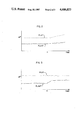
- FIGS. 2-4 illustrate plots of pressure drop verses time data
- FIG. 5 illustrates a plot of OHTR verses time of the pilot condenser.
- a pilot scale condenser is used in the prediction and detection of plant fouling.
- This condenser should be of a design suited to approximate the environment of the cooling water side of the plant condenser. It is not necessary that the conditions of the steam or "shell" side of the plant condenser be duplicated in the pilot condenser. This is so because shell side fouling is distinct from cooling water side fouling and it is dealt with on a different basis. It is therefore not of great interest in this situation.
- the cooling water side conditions of the plant condenser may be said to be adequately approximated by the pilot condenser when the water velocity through the two consensors are approximately the same, the inlet cooling water temperature of the two condensers are approximately the same, the outlet water temperatures of the two condensers are also approximately the same and the dimensions of the condenser tubes are approximately the same.
- the pilot condenser will, of course, ordinarily have fewer condenser tubes than the plant condenser.
- the composition, length and diameter of the condenser tubes in the two condensers should also be similar.
- the condenser tubes in the pilot condenser may be "folded" into a multiple-pass arrangement in order to make the size of the pilot condenser more manageable. Folding will result in an increased pressure drop across the condenser tubes, however, this is acceptable since the method of this invention is concerned with deviation of the pressure drop from a baseline value.
- pilot condenser Other plant operating conditions which may be approximated in the pilot condenser include the type and concentration of anti-microfouling agents which are added to the cooling water. When the plant condenser is removed from service or de-watered, the same can be done to the pilot condenser. Also, whenever the plant condenser is cleaned to remove microfouling material such as by the use of brushes, acid solutions or high pressure water, the same operation should be performed on the pilot condenser. This should include both on-line and off-line condenser cleaning operations.
- the present method may be successfully carried out when the pilot condenser is operated at conditions which are initially fixed to conditions that are generally representative of plant condenser operating conditions
- the accuracy and reliability of the method of this invention increases when the operating conditions of the pilot condenser are frequently adjusted so as to maintain them in close approximation to those of the plant condenser. This may be accomplished by frequent manual adjustments or, preferably, by the use of automatic sensors in the plant condenser which provide data to a computer which constantly regulates the pilot condenser's operation.
- baseline pressure drop values should be established. This will usually involve the operation of the condenser units for a sufficient time to reach a steady state of isothermal heat exchange and the collection of a representative amount of baseline data. The amount of time and data required will vary with the specific condensers used, but will be readily ascertainable to one of skill in the art.
- Microfouling is usually a slow, gradual process and is indicated by a slow, gradual increase in the pressure drop in both condensers. Macrofouling is usually a more rapidly developing phenomenon than microfouling. Typically, clean, clear tubes will be suddenly occluded by dead fish or the like. This will generally result in a sharper, more rapid change in pressure drop and will not be seen in both condensers (i.e., macrofouling will be seen only in the condenser where the dead fish are caught in the condenser tubes). Thus, by monitoring the pressure drop across the plant and pilot condenser, microfouling and macrofouling can be both detected and distinguished.
- pilot condenser inlet cooling water is continuously screened by means of an additional screening device and the screening device is frequently cleaned or replaced. This can be done so as to effectively eliminate the possibility of macrofouling in the pilot condenser and also eliminates the possibility that the pilot and plant condensers will be simultaneously macrofouled.
- the OHTR of the pilot condenser may be monitored as part of the process of the present invention in order to provide confirmation of the indications provided by the pressure drop measurements. This simultaneous monitoring of these two parameters provides an even more reliable indication of the microfouling condition of the plant condenser.
- FIG. 1 we see an illustration of a condenser system which is suitable for use in the process of the present invention.
- the plant condenser 10 has a cooling water inlet box 12, a cooling water outlet box 14 and steam inlets and outlets (not shown).
- Inlet box 12 and outlet box 14 are fed by inlet pipe 13 and outlet pipe 15 respectively.
- Pressure probes 16 and 18 are located at pipes 13 and 15 respectively.
- Temperature probes 17 and 19 are also provided at inlet pipe 12 and outlet pipe 15 respectively.
- a pilot condenser cooling water supply line 20 draws cooling water from inlet box 12 and supplies cooling water to the pilot condenser 22.
- pilot condenser 22 Within the pilot condenser 22 is an array of condenser tubes (not shown). These tubes are about the same length as the condenser tubes in the plant condenser but are folded within the pilot condenser. The tubes in this illustration are folded an even number of times and the outlets and inlets are therefore on the same end of the condenser.
- a pilot condenser cooling water return line 24 returns the used cooling water to the outlet box 14.
- Pressure probes 26 and 28 are provided at the cooling water inlet and outlet respectively of the pilot condenser 22.
- a strainer 30, a pump 32 and a flow controller 34 are located at the cooling water inlet of the pilot condenser 22.
- Temperature probes 36 and 38 are provided at the cooling water inlet and outlet respectively.
- a heating unit 40 provides hot water to the pilot condenser 22. The hot water is circulated through the pilot condenser 22 by a pump 42.
- the hot water circuit may be provided with suitable temperature, flow and pressure control devices.
- the plant condenser is operated as usual and the pilot condenser is operated so that a steady rate, isothermal heat exchange takes place.
- the temperature of the water in inlet 20 and inlet box 12 should be approximately equal as should the temperature of the water in outlet 24 and outlet box 14.
- the pressure drop across the condenser tubes of pilot condenser 22 and plant condenser 10 are measured and base line values for each condenser are established.
- FIG. 2 which is a plot of pressure drop versus time illustrates how this data is used in the present process.
- the solid line represents the pressure drop in the plant condenser 10 and the dashed line represents the pressure drop in the pilot condenser 22. Following these plots through time, one may see that baseline values are first established. Later, an increase in the pressure drop of both units is seen at about time A. This indicates that both units have begun to experience microfouling. The degree of fouling at time A is probably not yet detrimental to the operation of the plant condenser but the plant operator now has an early warning of microfouling.
- FIG. 3 represents the pressure drop data obtained under different circumstances. Following this plot through time we see the establishment of baseline values. Then, at about time A, the pressure drop across the plant condenser increases while the drop across the pilot condenser 22 remains steady. This indicates that the screening of the condenser cooling water has been ineffective and that macrofouling of the plant condenser 10 has occured.
- FIG. 4 illustrates yet another operating condition.
- the pressure drops across the condensers first reaches baseline values and then, at time A, both plots show an increase in pressure drop just as was seen in FIG. 2. Then, at time B, the plant condenser displays a jump in pressure drop. This data indicates that both units are experiencing microfouling and that, as of about time B, the plant condenser is also experiencing macrofouling.
- FIG. 5 illustrates the use of the OHTR of the pilot condenser 22 as an additional indicator of microfouling.
- FIG. 4 which represents data obtained under conditions which are the same as those illustrated in FIG. 2, the OHTR of the pilot condenser 22 is plotted versus time. As the system is operated a shift in the OHTR is seen at time A, which corresponds to time A in FIG. 2. This provides independent confirmation that microfouling is occuring and makes such a judgment possible on the basis of far subtler changes in the data than would be possible if either one of these indicators were used alone.
- the OHTR may be determined in a conventional manner, such as is described in Guerra, et al. supra. It will be appreciated that the OHTR should be determined under such conditions that changes in the OHTR will reflect changes in the fouling condition of the condenser and not changes in the other variables which can influence the OHTR.
Landscapes
- Life Sciences & Earth Sciences (AREA)
- Biodiversity & Conservation Biology (AREA)
- Ecology (AREA)
- Environmental & Geological Engineering (AREA)
- Environmental Sciences (AREA)
- Physics & Mathematics (AREA)
- Health & Medical Sciences (AREA)
- Chemical & Material Sciences (AREA)
- Analytical Chemistry (AREA)
- Biochemistry (AREA)
- General Health & Medical Sciences (AREA)
- General Physics & Mathematics (AREA)
- Immunology (AREA)
- Pathology (AREA)
- Monitoring And Testing Of Nuclear Reactors (AREA)
Abstract
Description
Claims (10)
Priority Applications (1)
| Application Number | Priority Date | Filing Date | Title |
|---|---|---|---|
| US06/745,668 US4686853A (en) | 1985-06-17 | 1985-06-17 | Method for the prediction and detection of condenser fouling |
Applications Claiming Priority (1)
| Application Number | Priority Date | Filing Date | Title |
|---|---|---|---|
| US06/745,668 US4686853A (en) | 1985-06-17 | 1985-06-17 | Method for the prediction and detection of condenser fouling |
Publications (1)
| Publication Number | Publication Date |
|---|---|
| US4686853A true US4686853A (en) | 1987-08-18 |
Family
ID=24997716
Family Applications (1)
| Application Number | Title | Priority Date | Filing Date |
|---|---|---|---|
| US06/745,668 Expired - Fee Related US4686853A (en) | 1985-06-17 | 1985-06-17 | Method for the prediction and detection of condenser fouling |
Country Status (1)
| Country | Link |
|---|---|
| US (1) | US4686853A (en) |
Cited By (7)
| Publication number | Priority date | Publication date | Assignee | Title |
|---|---|---|---|---|
| US4762168A (en) * | 1985-11-28 | 1988-08-09 | Sumitomo Light Metal Industries, Ltd. | Condenser having apparatus for monitoring conditions of inner surface of condenser tubes |
| US4997574A (en) * | 1989-09-01 | 1991-03-05 | Lehigh University | Staged boundary layer treatment method and system for biofouling control |
| US5083606A (en) * | 1990-08-09 | 1992-01-28 | Texas Utilities Electric Company | Structure and method for on-line inspection of condenser tubes |
| US5176199A (en) * | 1990-09-14 | 1993-01-05 | Taprogge Gmbh | Method for measuring the cleaning effectiveness of cleaning bodies on heat exchangers |
| WO2000034758A1 (en) * | 1998-12-11 | 2000-06-15 | Buckman Laboratories International, Inc. | A biofouling monitor and methods to monitor or detect biofouling |
| WO2015002966A1 (en) * | 2013-07-01 | 2015-01-08 | Knew Value, LLC | Heat exchanger testing device |
| US10234361B2 (en) | 2013-07-01 | 2019-03-19 | Knew Value Llc | Heat exchanger testing device |
Citations (7)
| Publication number | Priority date | Publication date | Assignee | Title |
|---|---|---|---|---|
| US3552189A (en) * | 1968-07-26 | 1971-01-05 | Commissariat Energie Atomique | Apparatus for detecting scale formation |
| US4044605A (en) * | 1974-11-15 | 1977-08-30 | Stal-Laval Apparat Ab | Apparatus for measuring fouling on the inside of a heat-exchanger tube |
| US4176544A (en) * | 1978-05-04 | 1979-12-04 | The British Petroleum Company Limited | Method for determining fouling |
| GB2068540A (en) * | 1980-01-31 | 1981-08-12 | Shell Int Research | Method and apparatus for testing the effectiveness of chemicals as scale inhibitors or scale removers |
| US4339945A (en) * | 1980-10-30 | 1982-07-20 | Drew Chemical Corporation | Process and apparatus for testing fluids for fouling |
| US4346587A (en) * | 1980-10-30 | 1982-08-31 | Drew Chemical Corporation | Process and apparatus for testing fluids for fouling and antifoulant protocol |
| US4521864A (en) * | 1982-09-30 | 1985-06-04 | Characklis William G | Measurement of build-up of fouling deposits by sensing flow characteristics during brief flow excursions |
-
1985
- 1985-06-17 US US06/745,668 patent/US4686853A/en not_active Expired - Fee Related
Patent Citations (7)
| Publication number | Priority date | Publication date | Assignee | Title |
|---|---|---|---|---|
| US3552189A (en) * | 1968-07-26 | 1971-01-05 | Commissariat Energie Atomique | Apparatus for detecting scale formation |
| US4044605A (en) * | 1974-11-15 | 1977-08-30 | Stal-Laval Apparat Ab | Apparatus for measuring fouling on the inside of a heat-exchanger tube |
| US4176544A (en) * | 1978-05-04 | 1979-12-04 | The British Petroleum Company Limited | Method for determining fouling |
| GB2068540A (en) * | 1980-01-31 | 1981-08-12 | Shell Int Research | Method and apparatus for testing the effectiveness of chemicals as scale inhibitors or scale removers |
| US4339945A (en) * | 1980-10-30 | 1982-07-20 | Drew Chemical Corporation | Process and apparatus for testing fluids for fouling |
| US4346587A (en) * | 1980-10-30 | 1982-08-31 | Drew Chemical Corporation | Process and apparatus for testing fluids for fouling and antifoulant protocol |
| US4521864A (en) * | 1982-09-30 | 1985-06-04 | Characklis William G | Measurement of build-up of fouling deposits by sensing flow characteristics during brief flow excursions |
Non-Patent Citations (2)
| Title |
|---|
| "Use of Pilot Scale Condensers For Biofouling Measurement And Control" C. R. Guerra et al. (1980). |
| Use of Pilot Scale Condensers For Biofouling Measurement And Control C. R. Guerra et al. (1980). * |
Cited By (10)
| Publication number | Priority date | Publication date | Assignee | Title |
|---|---|---|---|---|
| US4762168A (en) * | 1985-11-28 | 1988-08-09 | Sumitomo Light Metal Industries, Ltd. | Condenser having apparatus for monitoring conditions of inner surface of condenser tubes |
| US4997574A (en) * | 1989-09-01 | 1991-03-05 | Lehigh University | Staged boundary layer treatment method and system for biofouling control |
| US5083606A (en) * | 1990-08-09 | 1992-01-28 | Texas Utilities Electric Company | Structure and method for on-line inspection of condenser tubes |
| US5176199A (en) * | 1990-09-14 | 1993-01-05 | Taprogge Gmbh | Method for measuring the cleaning effectiveness of cleaning bodies on heat exchangers |
| WO2000034758A1 (en) * | 1998-12-11 | 2000-06-15 | Buckman Laboratories International, Inc. | A biofouling monitor and methods to monitor or detect biofouling |
| US6311546B1 (en) | 1998-12-11 | 2001-11-06 | Buckman Laboratories International, Inc. | Biofouling monitor and methods to monitor or detect biofouling |
| CN100389317C (en) * | 1998-12-11 | 2008-05-21 | 巴科曼实验室国际公司 | Biofouling monitor and method of monitoring or detecting biofouling |
| WO2015002966A1 (en) * | 2013-07-01 | 2015-01-08 | Knew Value, LLC | Heat exchanger testing device |
| US9778147B2 (en) | 2013-07-01 | 2017-10-03 | Knew Value, LLC | Heat exchanger testing device |
| US10234361B2 (en) | 2013-07-01 | 2019-03-19 | Knew Value Llc | Heat exchanger testing device |
Similar Documents
| Publication | Publication Date | Title |
|---|---|---|
| US5070468A (en) | Plant fault diagnosis system | |
| EP0351833B1 (en) | Plant fault diagnosis system | |
| JP7344201B2 (en) | Cooling water monitoring and control system | |
| US4390058A (en) | Method of monitoring condenser performance and system therefor | |
| EP2951653B1 (en) | A method for providing maintenance data | |
| US20080183427A1 (en) | Heat Exchanger Fouling Detection | |
| US5385202A (en) | Method and apparatus for operational monitoring of a condenser with tubes, by measurements at selected tubes | |
| EP0496333B1 (en) | Nuclear plant diagnosis apparatus and method | |
| US4686853A (en) | Method for the prediction and detection of condenser fouling | |
| US4339945A (en) | Process and apparatus for testing fluids for fouling | |
| CN87107624A (en) | The intelligent monitor system of chemical process | |
| CN104801096B (en) | Intelligent pre-filter online monitoring and diagnosing device and method | |
| KR920005799A (en) | Method and system for controlling the operation of steam condensers in power plants | |
| JP4426113B2 (en) | Biofouling monitor and method for monitoring or detecting biofouling | |
| US5836201A (en) | Methods and apparatus for measuring the flow rate of solvent recovery in solvent recovery dryers. | |
| CA1173159A (en) | Process and apparatus for testing fluids for fouling and antifoulant protocol | |
| US7690245B2 (en) | Device for testing at least one quality parameter of a fluid | |
| Bockhorst et al. | MSET modeling of Crystal River-3 venturi flow meters. | |
| EP1376112B1 (en) | Method for controlling a cleaning progress of coatings on a working member | |
| AU2011318462B2 (en) | Method of detection of contamination using fluorescence technology | |
| JP3670468B2 (en) | Local oil flushing method for rotating electrical machines | |
| EP1857802B1 (en) | Automatic quality control method for the water-vapour cycles in power stations | |
| EP1135646A1 (en) | Method and system for monitoring the condition of lubricated parts | |
| Juuso et al. | Feature extraction for vibration analysis of cavitation in Kaplan water turbines | |
| CA1297985C (en) | Plant fault diagnosis system |
Legal Events
| Date | Code | Title | Description |
|---|---|---|---|
| AS | Assignment |
Owner name: PUBLIC SERVICE ELECTRIC AND GAS CO., 80 PARK PLAZA Free format text: ASSIGNMENT OF ASSIGNORS INTEREST.;ASSIGNOR:ARNOLD, HERBERT S.;REEL/FRAME:004836/0130 Effective date: 19871231 Owner name: PUBLIC SERVICE ELECTRIC AND GAS CO., 80 PARK PLAZA Free format text: ASSIGNMENT OF ASSIGNORS INTEREST.;ASSIGNORS:ARNOLD, HERBERT, S., JR.;SUGAM, RICHARD J.;REEL/FRAME:004836/0134 Effective date: 19880104 Owner name: PUBLIC SERVICE ELECTRIC AND GAS CO., A CORP. OF N Free format text: ASSIGNMENT OF ASSIGNORS INTEREST;ASSIGNOR:ARNOLD, HERBERT S.;REEL/FRAME:004836/0130 Effective date: 19871231 Owner name: PUBLIC SERVICE ELECTRIC AND GAS CO., A CORP. OF N Free format text: ASSIGNMENT OF ASSIGNORS INTEREST;ASSIGNORS:ARNOLD, HERBERT, S., JR.;SUGAM, RICHARD J.;REEL/FRAME:004836/0134 Effective date: 19880104 |
|
| FPAY | Fee payment |
Year of fee payment: 4 |
|
| REMI | Maintenance fee reminder mailed | ||
| LAPS | Lapse for failure to pay maintenance fees | ||
| FP | Lapsed due to failure to pay maintenance fee |
Effective date: 19950823 |
|
| STCH | Information on status: patent discontinuation |
Free format text: PATENT EXPIRED DUE TO NONPAYMENT OF MAINTENANCE FEES UNDER 37 CFR 1.362 |