US4682000A - Welding transformer and rectifier assembly - Google Patents
Welding transformer and rectifier assembly Download PDFInfo
- Publication number
- US4682000A US4682000A US06/712,796 US71279685A US4682000A US 4682000 A US4682000 A US 4682000A US 71279685 A US71279685 A US 71279685A US 4682000 A US4682000 A US 4682000A
- Authority
- US
- United States
- Prior art keywords
- pads
- transformer
- rectifier
- bus
- turns
- Prior art date
- Legal status (The legal status is an assumption and is not a legal conclusion. Google has not performed a legal analysis and makes no representation as to the accuracy of the status listed.)
- Expired - Lifetime
Links
- 238000003466 welding Methods 0.000 title abstract description 11
- 239000011800 void material Substances 0.000 claims description 7
- 239000000463 material Substances 0.000 claims 1
- 239000004020 conductor Substances 0.000 description 5
- 230000000712 assembly Effects 0.000 description 3
- 238000000429 assembly Methods 0.000 description 3
- 230000001939 inductive effect Effects 0.000 description 3
- RYGMFSIKBFXOCR-UHFFFAOYSA-N Copper Chemical compound [Cu] RYGMFSIKBFXOCR-UHFFFAOYSA-N 0.000 description 2
- XUIMIQQOPSSXEZ-UHFFFAOYSA-N Silicon Chemical compound [Si] XUIMIQQOPSSXEZ-UHFFFAOYSA-N 0.000 description 2
- 239000011324 bead Substances 0.000 description 2
- 238000010276 construction Methods 0.000 description 2
- 229910052802 copper Inorganic materials 0.000 description 2
- 239000010949 copper Substances 0.000 description 2
- 229910052710 silicon Inorganic materials 0.000 description 2
- 239000010703 silicon Substances 0.000 description 2
- XLYOFNOQVPJJNP-UHFFFAOYSA-N water Substances O XLYOFNOQVPJJNP-UHFFFAOYSA-N 0.000 description 2
- BQCADISMDOOEFD-UHFFFAOYSA-N Silver Chemical compound [Ag] BQCADISMDOOEFD-UHFFFAOYSA-N 0.000 description 1
- 230000004075 alteration Effects 0.000 description 1
- 238000004581 coalescence Methods 0.000 description 1
- 238000001816 cooling Methods 0.000 description 1
- 238000004519 manufacturing process Methods 0.000 description 1
- KERTUBUCQCSNJU-UHFFFAOYSA-L nickel(2+);disulfamate Chemical compound [Ni+2].NS([O-])(=O)=O.NS([O-])(=O)=O KERTUBUCQCSNJU-UHFFFAOYSA-L 0.000 description 1
- 229910052709 silver Inorganic materials 0.000 description 1
- 239000004332 silver Substances 0.000 description 1
- 229910001220 stainless steel Inorganic materials 0.000 description 1
- 239000010935 stainless steel Substances 0.000 description 1
Images


Classifications
-
- H—ELECTRICITY
- H01—ELECTRIC ELEMENTS
- H01F—MAGNETS; INDUCTANCES; TRANSFORMERS; SELECTION OF MATERIALS FOR THEIR MAGNETIC PROPERTIES
- H01F27/00—Details of transformers or inductances, in general
- H01F27/28—Coils; Windings; Conductive connections
- H01F27/2823—Wires
- H01F27/2828—Construction of conductive connections, of leads
-
- H—ELECTRICITY
- H01—ELECTRIC ELEMENTS
- H01F—MAGNETS; INDUCTANCES; TRANSFORMERS; SELECTION OF MATERIALS FOR THEIR MAGNETIC PROPERTIES
- H01F27/00—Details of transformers or inductances, in general
- H01F27/40—Structural association with built-in electric component, e.g. fuse
-
- H—ELECTRICITY
- H01—ELECTRIC ELEMENTS
- H01F—MAGNETS; INDUCTANCES; TRANSFORMERS; SELECTION OF MATERIALS FOR THEIR MAGNETIC PROPERTIES
- H01F27/00—Details of transformers or inductances, in general
- H01F27/40—Structural association with built-in electric component, e.g. fuse
- H01F2027/408—Association with diode or rectifier
Definitions
- the present invention relates to welding transformers and rectifiers, and more particularly to transformers and rectifiers for robotic welders.
- a resistance welder In resistance welding, coalescence is produced primarily by resistive heat created by passing an electric current through the workpiece.
- a resistance welder includes primary conductors, a transformer, secondary conductors, and welding electrodes.
- the primary conductors couple the transformer to a power source.
- the secondary conductors interconnect the transformer and the electrodes.
- the primary power source or supply in resistance welding provides power at the line frequency--for example, 60 hertz (Hz) in the United States and 50 Hz in Europe.
- Welding transformers for this relatively low-frequency current are excessively heavy for many robotic welders where weight is a primary consideration.
- the rectifier assembly directly abuts the secondary pads of the transformer to eliminate inductive throats therebetween.
- the transformer includes a pair of secondary pads, at least one diode overlying and abutting each secondary pad, and a rectified bus overlying and abutting the diodes. Consequently, a rectified current is outputted on the rectified bus.
- the sandwiching of the diodes directly against the secondaries greatly reduces both the profile of the transformer and its weight. Inductance due to electrical connections between the transformer and the rectifier assembly are virtually eliminated. The unit therefore provides improved performance in a smaller and lighter weight package than known units.
- the common bus of the transformer is configured to further reduce the size and weight of the unit.
- the transformer includes a pair of coplanar secondary pads, a planar common bus overlying the secondary pads, and a plurality of secondary coil turns.
- Each turn includes a first end connected to the common bus and a second end extending through or beyond the common bus and connected to one of the secondary pads.
- the bus defines some apertures permitting the second turn ends to extend therethrough without electrically contacting the bus. This intermeshing of the coil turns and common bus further reduces the transformer unit size and weight.
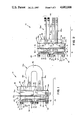
- FIG. 1 is a side plan view of the welding transformer and rectifier assembly of the present invention
- FIG. 2 is a top elevational view of the assembly
- FIG. 3 is an end elevational view taken from the right side of FIG. 2;
- FIG. 4 is an end elevational view taken from the left side of FIG. 2;
- FIG. 5 is a view taken along plane V--V in FIG. 2;
- FIG. 6 is a view taken along plane VI--VI in FIG. 2;
- FIG. 7 is an elevational view of the common bus.
- the transformer includes a transformer portion 12 and a rectifier portion 14 (FIGS. 1 and 2).
- the transformer portion 12 includes a pair of generally coplanar secondary connectors or pads 16a and 16b, a common bus 18, and a secondary coil 20.
- Each turn of the coil 20 includes a first end electrically connected to the common bus 18 and a second end electrically connected to one of pads 16a and 16b.
- the common bus 18 is configured to permit the second end of each turn to extend therethrough without electrically contacting the bus.
- the rectifier portion 14 includes a plurality of disk diodes 22a and 22b sandwiched against the secondary pads 16a and 16b, respectively, and a rectified bus 24 sandwiched against the diodes 22. Alternating current on the secondary pads 16 is rectified to single-phase DC current on the rectified bus 24.
- Each of the secondary pads 16 is a generally rectangular parallelepiped.
- Each secondary pad 16 includes a coil face 26 and an opposite rectifier face 28.
- the coil faces 26 of the two pads are coplanar, and the rectifier faces 28 are also coplanar and parallel to the coil faces.
- wear pads 30 can be mounted on rectifier faces 28. If included, each wear pad 30 preferably extends the full height and width of the secondary pad 16 on which it is mounted.
- the secondary pads 16 define slots 32 in their coil faces 26 to receive the coils 20.
- the pads also define tapped bores 33 to receive bolts 70 as will be described.
- the common bus 18 (FIGS. 1-3 and 7) is generally planar and generally parallel to the secondary pads 16.
- the common bus 18 includes a pad face 34 and a coil face 36, which are parallel to one another.
- the common bus 18 includes a terminal portion 38 defining tapped bores 40 which receive electrical connectors in conventional fashion.
- the common bus 18 also defines a pair of rectangular apertures or voids 42b and 42d (FIG. 7) which extend through the common bus to receive certain coil ends as will be described.
- Opposite terminal edge 38 are a pair of arms 44a and 44b which define a void or open-sided aperture 42c therebetween.
- a fourth void or open-sided aperture 42d is located directly below arm 44a.
- a plurality of slots or recesses 46a, 46b, 46c, and 46d are formed in the coil face 36 of the common bus 18 to receive coil ends.
- the turns or loops of secondary coil 20 are generally identical to one another.
- the turns are grouped into two sets of physically alternating turns or every other turn--a first set including turns 20a and 20c and a second set including turns 20b and 20d.
- Each of the turns 20 is extruded copper and preferably hollow to permit water cooling.
- the turn 20a (FIGS. 1 and 2) includes a bight portion 48 and a pair of legs 50a and 50b extending therefrom.
- the legs 50 are generally physically parallel to one another, and leg 50a is longer than 50b.
- Leg 50a includes a pad end 52a which extends through void 42a in the common bus and is electrically connected to the secondary pad 16b. Leg 50a therefore does not contact the common bus 18 but only the secondary pad 16b.
- the turn end 52a is silver soldered in the slot 32 in the secondary pad 16b.
- the shorter leg 50b includes a bus end 52b positioned within slot 46a of the common bus 18. Consequently, leg 50b does not extend through the common bus, but rather is electrically connected thereto.
- Turn 20c is identical to turn 20a and includes a longer leg 50a, which extends through void 42c in the common bus 18 and is connected to pad 16b, and a shorter leg 50b which is electrically connected to the common bus in slot 46c. Consequently, the first set of turns 20a and 20c is electrically connected to the common bus 18 and to the secondary pad 16b.
- the common bus 18 is configured to receive the long legs 50a of turns 20a and 20c therethrough.
- Turns 20b and 20d are generally identical to turns 20a and 20c but are rotated 180 degrees or "flipped over”. Consequently, longer legs 50a of turns 20b and 20d extend through voids 42b and 42d, respectively, in the common bus 18 to be electrically connected to the secondary pad 16a. The shorter legs 50b of turns 20b and 20d are electrically connected to the common bus 18 within slots 46b and 46d, respectively. Consequently, the turns 20b and 20d of the second set are electrically connected to the common bus 18 and to the secondary pad 16a.
- the rectifier portion 14 (FIGS. 1-2) includes generally planar disk diodes 22, rectified bus 24, and spring assemblies 54.
- the spring assemblies 54 are anchored to the secondary pads 16 to urge the rectified bus 24 agains the disk diodes 22 and therefore sandwich the disk diodes between the rectified bus and the secondary pads 16.
- Disk diodes 22 are generally well-known to those in the diode art. These diodes are preferably 52 millimeter diodes sold as Model No. R9KN0610 by Westinghouse. Typically, such disk diodes include an overflow silicon bead about the periphery edge of one face formed during manufacture. Other diodes could be substituted therefor.
- Rectified bus 24 (FIGS. 1-2 and 6) is generally planar and generally parallel to the disk diodes 22 and the secondaries 16.
- the rectified bus 24 includes a diode face 56 and a spring face 58 generally parallel to one another.
- the diode face defines four circular grooves 60 to each receive the silicon bead of a disk diode 22 permitting the bus 24 to fully abut the faces of the diodes.
- Each groove 60 is flanked by four throughbores 62 spaced evenly thereabout.
- the rectified bus 24 includes a terminal portion 64 defining a pair of threaded bores 66 to receive conventional electrical connectors.
- the secondary pads 16, common bus 18, and rectified bus 24 are all fabricated of copper stock having a low-stress sulfamate nickel plate. Other suitable electrically conductive materials could also be substituted. Additionally, secondary pads 16, common bus 18, coils 20, and rectified bus 24 are water cooled in conventional fashion (not shown).
- the four spring assemblies are generally identical to one another and are included to accommodate thermal expansion in the unit.
- One spring assembly 54 is positioned over each of diodes 22 so that the spring force against each diode independently adjustable.
- Each assembly 54 includes a stack of spring washers 67, a back-up plate 68, and bolts 70.
- the spring washers 67 are known in the industry as Belville springs.
- Back-up plate 68 sandwiches the spring washers 67 against the rectified bus 24.
- bolts 70 extend through back-up plate 68 and the bores 62 in the rectified bus 24 and are threadedly received in the apertures 33 in the secondary pads 16.
- a stainless steel washer 72 and on insulated washer 74 are positioned over each of bolts 70 between the head and the back-up plate 68. Additionally, an insulated sleeve 76 (only one shown in FIG. 1) is positioned over each bolt 70 and extends through the back-up plate 68 and the rectified bus 24. Therefore, bolts 70 are electrically connected to the secondary pad 16 in which they are anchored and electrically insulated from the rectified bus 24 and the back-up plates 68. The sleeves 76 support and position the diodes 22.
- a primary coil (not shown) and a core (not shown) are installed in conjunction with the secondary coil 20 in conventional fashion.
- the secondary connectors or pads 16, the common bus 18, the coil 20, the priamry coil, and the core are potted for electrical, thermal, and structural integrity.
- Bolts 70 are carefully torqued to provide a desired spring force against the rectified bus 24 through spring washers 66. In the preferred embodiment, the desired spring force is 5500 pounds.
- Electrical connectors (not shown) are secured to the common bus 18 at bores 40 in the terminal portion 38.
- electrical connectors (not shown) are secured to the rectified bus 24 in the bores 66 in terminal portion 64.
- the transformer is then ready for use particularly in conjunction with a robotic welder.
- a primary voltage is applied to the primary coils (not shown) at approximately 1200 Hz.
- the relatively high frequency enables the transformer to be much smaller and lighter than those transformers utilizing line frequencies.
- a secondary voltage is induced in the secondary coil 20 which appears as an alternating voltage across the secondary pads 16a and 16b. This alternating current is rectified through diodes 22 so that single-phase full-wave DC current is applied to the rectified bus 24. Consequently, the transformer and rectifier unit supplies a DC voltage to eliminate reactance problems. Further, the described configuration is extremely compact and lightweight enabling the transformer to be used in a wide variety of robotic and fixture type applications where both size and weight are significant constraints.
Landscapes
- Engineering & Computer Science (AREA)
- Power Engineering (AREA)
- Rectifiers (AREA)
Abstract
Description
Claims (20)
Priority Applications (7)
| Application Number | Priority Date | Filing Date | Title |
|---|---|---|---|
| US06/712,796 US4682000A (en) | 1985-03-18 | 1985-03-18 | Welding transformer and rectifier assembly |
| AU54331/86A AU594043B2 (en) | 1985-03-18 | 1986-03-03 | Welding transformer and rectifier assembly |
| CA000503150A CA1276974C (en) | 1985-03-18 | 1986-03-03 | Welding transformer and rectifier assembly |
| JP61056731A JPS61224862A (en) | 1985-03-18 | 1986-03-14 | Assembly of transformer and rectifier |
| MX001910A MX165689B (en) | 1985-03-18 | 1986-03-18 | TRANSFORMER AND RECTIFIER SET TO WELD |
| EP86301975A EP0199456B1 (en) | 1985-03-18 | 1986-03-18 | Electric transformer, possibly in combination with a rectifier |
| DE8686301975T DE3688440T2 (en) | 1985-03-18 | 1986-03-18 | ELECTRICAL TRANSFORMER EVENTLY COMBINED WITH RECTIFIER. |
Applications Claiming Priority (1)
| Application Number | Priority Date | Filing Date | Title |
|---|---|---|---|
| US06/712,796 US4682000A (en) | 1985-03-18 | 1985-03-18 | Welding transformer and rectifier assembly |
Publications (1)
| Publication Number | Publication Date |
|---|---|
| US4682000A true US4682000A (en) | 1987-07-21 |
Family
ID=24863598
Family Applications (1)
| Application Number | Title | Priority Date | Filing Date |
|---|---|---|---|
| US06/712,796 Expired - Lifetime US4682000A (en) | 1985-03-18 | 1985-03-18 | Welding transformer and rectifier assembly |
Country Status (7)
| Country | Link |
|---|---|
| US (1) | US4682000A (en) |
| EP (1) | EP0199456B1 (en) |
| JP (1) | JPS61224862A (en) |
| AU (1) | AU594043B2 (en) |
| CA (1) | CA1276974C (en) |
| DE (1) | DE3688440T2 (en) |
| MX (1) | MX165689B (en) |
Cited By (6)
| Publication number | Priority date | Publication date | Assignee | Title |
|---|---|---|---|---|
| DE3928881A1 (en) * | 1989-08-31 | 1991-03-14 | Niepenberg Dalex Werke | DIODE ARRANGEMENT IN RESISTANCE WELDING MACHINES |
| US5023423A (en) * | 1988-12-27 | 1991-06-11 | Honda Giken Kogyo Kabushiki Kaisha | Transformer apparatus with rectifiers |
| US5053599A (en) * | 1989-05-15 | 1991-10-01 | Honda Giken Kogyo Kabushiki Kaisha | Welding gun assembly with transformers |
| DE29705789U1 (en) * | 1997-04-02 | 1997-06-05 | Expert Maschinenbau Gmbh, 64653 Lorsch | transformer |
| US20140313679A1 (en) * | 2011-10-31 | 2014-10-23 | Fronius International Gmbh | Heavy-current transformer having a multi-point contacting, transformer element, contact plate and secondary winding, and method for producing such a heavy-current transformer |
| RU2647876C1 (en) * | 2017-04-19 | 2018-03-21 | Алексей Александрович Никифоров | Welding transformer |
Families Citing this family (1)
| Publication number | Priority date | Publication date | Assignee | Title |
|---|---|---|---|---|
| US4754390A (en) * | 1987-04-29 | 1988-06-28 | International Business Machines Corporation | Conductively cooled switching regulator |
Citations (15)
| Publication number | Priority date | Publication date | Assignee | Title |
|---|---|---|---|---|
| US2181644A (en) * | 1938-06-02 | 1939-11-28 | Thomson Gibb Electric Welding | Electric transformer |
| US2535554A (en) * | 1949-01-24 | 1950-12-26 | Shell Dev | Close-coupled electrical transformer |
| US3495067A (en) * | 1965-09-01 | 1970-02-10 | David Sciaky | Resistance welding machine |
| US3663790A (en) * | 1969-05-22 | 1972-05-16 | Bernard Humblot | Electrical transformer apparatus |
| US3725632A (en) * | 1970-03-25 | 1973-04-03 | Evg Entwicklung Verwert Ges | Multiple spot welding machines |
| US3742334A (en) * | 1971-07-02 | 1973-06-26 | C Leathers | Low inductance unit particularly for electric welders |
| US3763344A (en) * | 1972-07-10 | 1973-10-02 | Dengensha Manuf Co Ltd | Industrial robot with a welding gun |
| US3832661A (en) * | 1971-11-29 | 1974-08-27 | R Sato | Transformer |
| US3840720A (en) * | 1973-03-05 | 1974-10-08 | E Wolf | Three-phase transformer-rectifier assembly for a welder |
| US4233488A (en) * | 1977-11-23 | 1980-11-11 | Schwartz Charles A | Deep throat resistance welder |
| USRE31444E (en) * | 1980-10-31 | 1983-11-15 | Two-phase transformer and welding circuit therefor | |
| US4485289A (en) * | 1982-07-29 | 1984-11-27 | Schwartz Charles A | Welding system |
| US4488135A (en) * | 1982-07-29 | 1984-12-11 | Schwartz Charles A | Transformer for welding gun |
| US4496821A (en) * | 1982-08-06 | 1985-01-29 | Marelco Power Systems, Inc. | Transformer for robot arms |
| US4571669A (en) * | 1983-09-13 | 1986-02-18 | Honda Giken Kogyo Kabushiki Kaisha | Transformer with rectifier |
Family Cites Families (4)
| Publication number | Priority date | Publication date | Assignee | Title |
|---|---|---|---|---|
| US3131331A (en) * | 1960-03-28 | 1964-04-28 | Gen Controls Co | Coil-rectifier structures |
| US3826967A (en) * | 1973-05-29 | 1974-07-30 | Pioneer Magnetics Inc | Low leakage secondary circuit for a power transformer including conductive strips forming the secondary and connections for rectifying diodes |
| JPS5675962A (en) * | 1979-11-22 | 1981-06-23 | Hitachi Ltd | Ignition coil of internal combustion engine |
| EP0105942B1 (en) * | 1982-10-08 | 1987-01-07 | ANT Nachrichtentechnik GmbH | Device for producing high dc voltages |
-
1985
- 1985-03-18 US US06/712,796 patent/US4682000A/en not_active Expired - Lifetime
-
1986
- 1986-03-03 CA CA000503150A patent/CA1276974C/en not_active Expired - Lifetime
- 1986-03-03 AU AU54331/86A patent/AU594043B2/en not_active Ceased
- 1986-03-14 JP JP61056731A patent/JPS61224862A/en active Pending
- 1986-03-18 DE DE8686301975T patent/DE3688440T2/en not_active Expired - Fee Related
- 1986-03-18 EP EP86301975A patent/EP0199456B1/en not_active Expired - Lifetime
- 1986-03-18 MX MX001910A patent/MX165689B/en unknown
Patent Citations (16)
| Publication number | Priority date | Publication date | Assignee | Title |
|---|---|---|---|---|
| US2181644A (en) * | 1938-06-02 | 1939-11-28 | Thomson Gibb Electric Welding | Electric transformer |
| US2535554A (en) * | 1949-01-24 | 1950-12-26 | Shell Dev | Close-coupled electrical transformer |
| US3495067A (en) * | 1965-09-01 | 1970-02-10 | David Sciaky | Resistance welding machine |
| US3663790A (en) * | 1969-05-22 | 1972-05-16 | Bernard Humblot | Electrical transformer apparatus |
| US3725632A (en) * | 1970-03-25 | 1973-04-03 | Evg Entwicklung Verwert Ges | Multiple spot welding machines |
| US3742334A (en) * | 1971-07-02 | 1973-06-26 | C Leathers | Low inductance unit particularly for electric welders |
| US3832661A (en) * | 1971-11-29 | 1974-08-27 | R Sato | Transformer |
| US3763344A (en) * | 1972-07-10 | 1973-10-02 | Dengensha Manuf Co Ltd | Industrial robot with a welding gun |
| US3840720A (en) * | 1973-03-05 | 1974-10-08 | E Wolf | Three-phase transformer-rectifier assembly for a welder |
| US4233488A (en) * | 1977-11-23 | 1980-11-11 | Schwartz Charles A | Deep throat resistance welder |
| USRE31444E (en) * | 1980-10-31 | 1983-11-15 | Two-phase transformer and welding circuit therefor | |
| US4485289A (en) * | 1982-07-29 | 1984-11-27 | Schwartz Charles A | Welding system |
| US4488135A (en) * | 1982-07-29 | 1984-12-11 | Schwartz Charles A | Transformer for welding gun |
| US4496821A (en) * | 1982-08-06 | 1985-01-29 | Marelco Power Systems, Inc. | Transformer for robot arms |
| US4571669A (en) * | 1983-09-13 | 1986-02-18 | Honda Giken Kogyo Kabushiki Kaisha | Transformer with rectifier |
| US4571669B1 (en) * | 1983-09-13 | 1996-08-27 | Honda Motor Co Ltd | Transformer with rectifier |
Cited By (9)
| Publication number | Priority date | Publication date | Assignee | Title |
|---|---|---|---|---|
| US5023423A (en) * | 1988-12-27 | 1991-06-11 | Honda Giken Kogyo Kabushiki Kaisha | Transformer apparatus with rectifiers |
| US5053599A (en) * | 1989-05-15 | 1991-10-01 | Honda Giken Kogyo Kabushiki Kaisha | Welding gun assembly with transformers |
| DE3928881A1 (en) * | 1989-08-31 | 1991-03-14 | Niepenberg Dalex Werke | DIODE ARRANGEMENT IN RESISTANCE WELDING MACHINES |
| DE29705789U1 (en) * | 1997-04-02 | 1997-06-05 | Expert Maschinenbau Gmbh, 64653 Lorsch | transformer |
| US6369680B1 (en) | 1997-04-02 | 2002-04-09 | Expert Maschinenbau Gmbh | Transformer |
| US20140313679A1 (en) * | 2011-10-31 | 2014-10-23 | Fronius International Gmbh | Heavy-current transformer having a multi-point contacting, transformer element, contact plate and secondary winding, and method for producing such a heavy-current transformer |
| US10141106B2 (en) * | 2011-10-31 | 2018-11-27 | Fronius International Gmbh | Heavy-current transformer having a multi-point contacting, transformer element, contact plate and secondary winding, and method for producing such a heavy-current transformer |
| US10325720B2 (en) | 2011-10-31 | 2019-06-18 | Fronius International Gmbh | Method for producing a heavy-current transformer |
| RU2647876C1 (en) * | 2017-04-19 | 2018-03-21 | Алексей Александрович Никифоров | Welding transformer |
Also Published As
| Publication number | Publication date |
|---|---|
| DE3688440D1 (en) | 1993-06-24 |
| DE3688440T2 (en) | 1993-08-26 |
| CA1276974C (en) | 1990-11-27 |
| AU5433186A (en) | 1986-09-25 |
| AU594043B2 (en) | 1990-03-01 |
| JPS61224862A (en) | 1986-10-06 |
| MX165689B (en) | 1992-12-01 |
| EP0199456A2 (en) | 1986-10-29 |
| EP0199456A3 (en) | 1987-07-15 |
| EP0199456B1 (en) | 1993-05-19 |
Similar Documents
| Publication | Publication Date | Title |
|---|---|---|
| US3955122A (en) | Heat sink mounting for controlled rectifiers | |
| US3826967A (en) | Low leakage secondary circuit for a power transformer including conductive strips forming the secondary and connections for rectifying diodes | |
| US4682000A (en) | Welding transformer and rectifier assembly | |
| US6369680B1 (en) | Transformer | |
| JP2672238B2 (en) | Transformer for welding machine | |
| JP2018190981A (en) | AC capacitor and its connection and operation method | |
| CA2006663C (en) | Transformer apparatus with rectifiers | |
| GB2243248A (en) | Welding transformer and method of manufacturing same | |
| US4292665A (en) | Output stage for switching regulated power supply | |
| US3840720A (en) | Three-phase transformer-rectifier assembly for a welder | |
| US2601240A (en) | Rectifier assembly of the dry disk type | |
| US3668506A (en) | Current and fluid conducting arrangements | |
| CN112820515B (en) | A low-voltage high-current power supply device | |
| US5430426A (en) | Transformer | |
| US4943904A (en) | D.C. power unit assembly including unitized single-phase D.C. power units | |
| US4754390A (en) | Conductively cooled switching regulator | |
| US4543552A (en) | Transformer, more especially a voltage dropping transformer for an electric welding machine | |
| CN215356681U (en) | Low-voltage high-current welding power supply device | |
| JPH07114170B2 (en) | Transformer device with rectifier | |
| RU2262763C2 (en) | Adjustable welding transformer | |
| CN214203388U (en) | Electronic power transformer with overheat protection | |
| CN215496245U (en) | Large-pulse-current-resistant continuously-adjustable inductor set | |
| CN224036191U (en) | A current transformer device | |
| CN216212717U (en) | Current three-phase balancer with wire fixing structure | |
| US12166425B2 (en) | Electric device for a converter, converter and arrangement with an electric machine and a converter |
Legal Events
| Date | Code | Title | Description |
|---|---|---|---|
| AS | Assignment |
Owner name: CONRAC CORPORATION 3560 CHICAGO DRIVE, HUDSONVILLE Free format text: ASSIGNMENT OF ASSIGNORS INTEREST.;ASSIGNORS:HOLT, GARY E.;SIEHLING, MARK B.;VAN ANTWERP, STANLEY R.;REEL/FRAME:004386/0141;SIGNING DATES FROM 19850312 TO 19850315 |
|
| STCF | Information on status: patent grant |
Free format text: PATENTED CASE |
|
| AS | Assignment |
Owner name: CONRAC CORPORATION, A NEW YORK CORP. Free format text: CHANGE OF NAME;ASSIGNOR:MARK IV OF AMHERST, INC.,;REEL/FRAME:004831/0685 Effective date: 19870622 Owner name: AMHERST, INC., Free format text: MERGER;ASSIGNOR:CONRAC CORPORATION;REEL/FRAME:004835/0652 Effective date: 19870622 Owner name: CONRAC CORPORATION, A NEW YORK CORP.,NEW YORK Free format text: CHANGE OF NAME;ASSIGNOR:MARK IV OF AMHERST, INC.,;REEL/FRAME:004831/0685 Effective date: 19870622 Owner name: AMHERST, INC., STATELESS Free format text: MERGER;ASSIGNOR:CONRAC CORPORATION;REEL/FRAME:004835/0652 Effective date: 19870622 |
|
| FEPP | Fee payment procedure |
Free format text: PAYOR NUMBER ASSIGNED (ORIGINAL EVENT CODE: ASPN); ENTITY STATUS OF PATENT OWNER: LARGE ENTITY |
|
| FEPP | Fee payment procedure |
Free format text: PAYOR NUMBER ASSIGNED (ORIGINAL EVENT CODE: ASPN); ENTITY STATUS OF PATENT OWNER: LARGE ENTITY Free format text: PAYER NUMBER DE-ASSIGNED (ORIGINAL EVENT CODE: RMPN); ENTITY STATUS OF PATENT OWNER: LARGE ENTITY |
|
| FPAY | Fee payment |
Year of fee payment: 4 |
|
| AS | Assignment |
Owner name: MARK IV INDUSTRIES, INC., ONE TOWNE CENTRE, 501 JO Free format text: ASSIGNMENT OF ASSIGNORS INTEREST.;ASSIGNOR:CONRAC CORPORATION, A CORP. OF NEW YORK;REEL/FRAME:005640/0813 Effective date: 19910322 |
|
| FEPP | Fee payment procedure |
Free format text: PAYER NUMBER DE-ASSIGNED (ORIGINAL EVENT CODE: RMPN); ENTITY STATUS OF PATENT OWNER: LARGE ENTITY Free format text: PAYOR NUMBER ASSIGNED (ORIGINAL EVENT CODE: ASPN); ENTITY STATUS OF PATENT OWNER: LARGE ENTITY |
|
| FPAY | Fee payment |
Year of fee payment: 8 |
|
| FPAY | Fee payment |
Year of fee payment: 12 |
|
| AS | Assignment |
Owner name: ROMAN MANUFACTURING, INC., MICHIGAN Free format text: ASSIGNMENT OF ASSIGNORS INTEREST;ASSIGNOR:MARK IV INDUSTRIES, INC.;REEL/FRAME:009808/0235 Effective date: 19981231 |