US4681663A - Bipolar electrode formation - Google Patents
Bipolar electrode formation Download PDFInfo
- Publication number
- US4681663A US4681663A US06/941,204 US94120486A US4681663A US 4681663 A US4681663 A US 4681663A US 94120486 A US94120486 A US 94120486A US 4681663 A US4681663 A US 4681663A
- Authority
- US
- United States
- Prior art keywords
- electrodes
- precursor
- electrolyte
- precursor electrodes
- disposed
- Prior art date
- Legal status (The legal status is an assumption and is not a legal conclusion. Google has not performed a legal analysis and makes no representation as to the accuracy of the status listed.)
- Expired - Fee Related
Links
Images
Classifications
-
- H—ELECTRICITY
- H01—ELECTRIC ELEMENTS
- H01M—PROCESSES OR MEANS, e.g. BATTERIES, FOR THE DIRECT CONVERSION OF CHEMICAL ENERGY INTO ELECTRICAL ENERGY
- H01M4/00—Electrodes
- H01M4/02—Electrodes composed of, or comprising, active material
- H01M4/04—Processes of manufacture in general
- H01M4/0438—Processes of manufacture in general by electrochemical processing
- H01M4/044—Activating, forming or electrochemical attack of the supporting material
- H01M4/0445—Forming after manufacture of the electrode, e.g. first charge, cycling
- H01M4/0447—Forming after manufacture of the electrode, e.g. first charge, cycling of complete cells or cells stacks
-
- H—ELECTRICITY
- H01—ELECTRIC ELEMENTS
- H01M—PROCESSES OR MEANS, e.g. BATTERIES, FOR THE DIRECT CONVERSION OF CHEMICAL ENERGY INTO ELECTRICAL ENERGY
- H01M4/00—Electrodes
- H01M4/02—Electrodes composed of, or comprising, active material
- H01M4/04—Processes of manufacture in general
- H01M4/0438—Processes of manufacture in general by electrochemical processing
-
- H—ELECTRICITY
- H01—ELECTRIC ELEMENTS
- H01M—PROCESSES OR MEANS, e.g. BATTERIES, FOR THE DIRECT CONVERSION OF CHEMICAL ENERGY INTO ELECTRICAL ENERGY
- H01M4/00—Electrodes
- H01M4/02—Electrodes composed of, or comprising, active material
- H01M4/36—Selection of substances as active materials, active masses, active liquids
- H01M4/38—Selection of substances as active materials, active masses, active liquids of elements or alloys
-
- H—ELECTRICITY
- H01—ELECTRIC ELEMENTS
- H01M—PROCESSES OR MEANS, e.g. BATTERIES, FOR THE DIRECT CONVERSION OF CHEMICAL ENERGY INTO ELECTRICAL ENERGY
- H01M4/00—Electrodes
- H01M4/02—Electrodes composed of, or comprising, active material
- H01M2004/026—Electrodes composed of, or comprising, active material characterised by the polarity
- H01M2004/029—Bipolar electrodes
-
- H—ELECTRICITY
- H01—ELECTRIC ELEMENTS
- H01M—PROCESSES OR MEANS, e.g. BATTERIES, FOR THE DIRECT CONVERSION OF CHEMICAL ENERGY INTO ELECTRICAL ENERGY
- H01M2300/00—Electrolytes
- H01M2300/0002—Aqueous electrolytes
- H01M2300/0014—Alkaline electrolytes
-
- H—ELECTRICITY
- H01—ELECTRIC ELEMENTS
- H01M—PROCESSES OR MEANS, e.g. BATTERIES, FOR THE DIRECT CONVERSION OF CHEMICAL ENERGY INTO ELECTRICAL ENERGY
- H01M4/00—Electrodes
- H01M4/02—Electrodes composed of, or comprising, active material
- H01M4/36—Selection of substances as active materials, active masses, active liquids
- H01M4/48—Selection of substances as active materials, active masses, active liquids of inorganic oxides or hydroxides
- H01M4/54—Selection of substances as active materials, active masses, active liquids of inorganic oxides or hydroxides of silver
-
- Y—GENERAL TAGGING OF NEW TECHNOLOGICAL DEVELOPMENTS; GENERAL TAGGING OF CROSS-SECTIONAL TECHNOLOGIES SPANNING OVER SEVERAL SECTIONS OF THE IPC; TECHNICAL SUBJECTS COVERED BY FORMER USPC CROSS-REFERENCE ART COLLECTIONS [XRACs] AND DIGESTS
- Y02—TECHNOLOGIES OR APPLICATIONS FOR MITIGATION OR ADAPTATION AGAINST CLIMATE CHANGE
- Y02E—REDUCTION OF GREENHOUSE GAS [GHG] EMISSIONS, RELATED TO ENERGY GENERATION, TRANSMISSION OR DISTRIBUTION
- Y02E60/00—Enabling technologies; Technologies with a potential or indirect contribution to GHG emissions mitigation
- Y02E60/10—Energy storage using batteries
Definitions
- This invention relates generally to electrochemical cells and, more particularly, this invention relates to bipolar electrodes and methods of formation thereof.
- Electrochemical cells utilizing bipolar electrode designs having reactive metal electrodes supported on substrate current collectors are well known. See, for example, Momyer et al, U.S. Pat. No. 4,269,907 (May 26, 1981), the disclosure of which is hereby incorporated by reference, wherein cells including an aqueous electrolyte, an anode of an alkali metal, such as lithium, for example, a cathode spaced from the anode, and an intercell electrical connector are disclosed.
- the cathode may comprise an electrochemically active material, such as silver oxide
- the electrolyte may comprise an aqueous alkaline solution.
- Momyer et al also disclose an electrochemical cell stack comprising a plurality of bipolar electrodes connected in series.
- bipolar electrodes wherein a cathode and an anode are disposed on opposite sides of an electrically conductive metallic substrate typically involves the oxidation or reduction (charging) of a precursor electrode material.
- a bipolar electrode with a cathode of silver oxide typically involves oxidation of elemental silver.
- the elemental silver of such precursor electrodes in sintered and then hot forged onto a substrate current collector.
- Nickel foil plated with silver, so as to facilitate adherence of elemental silver thereto, is commonly used as a substrate current collector for such bipolar electrodes.
- the hot forgings of elemental silver are assembled into a stack in which the elemental silver and counter electrodes of nickel foil are alternated, with the elemental silver electrodes in the charging stack electrically connected in parallel to attachment to the positive post of a DC power supply. Further, all the nickel foil substrates of the counter electrodes are electrically connected in parallel for attachment to the negative post of the DC power supply.
- the stack is then placed into an electrolyte solution which permits the electrical contact between the precursor electrodes and the counter electrode that is necessary for the reduction or oxidation of the material of the precursor electrodes.
- the conventional electrode formation technique of parallel oxidation is frequently accompanied by undesirable bending of the electrodes.
- the silver oxide electrodes resulting from the use of the above-identified method of oxidation are frequently of a bent, irregular shape. This bending of the electrodes is believed to be largely a result of the stoichiometric and molar volume changes which occur during electrode formation upon oxidation of the electroactive material while the substrate is unchanged and is commonly referred to as "potato chipping".
- the first step may be represented by the following equation:
- Reaction (1) occurs at a standard reduction/oxidation potential of about 0.34 V which is below the voltage at which oxygen evolution will occur, i.e., the standard redox potential of oxygen is about 0.401 volt.
- elemental silver can be directly oxidized to the divalent level as shown by equation 2B:
- the electrolyte used in electrode formation systems is circulated so as to minimize the likelihood of the formation of colloidal silver short circuits during the electrode formation process.
- the formation of colloidal silver short circuits is a stochastic process and colloidal silver short circuits may be formed even when a flowing electrolyte is used.
- a system useful in the formation of electrodes for use in electrochemical cells comprises a power supply and a pair of conductive end electrodes spaced apart from one another with a pair of precursor electrodes positioned therebetween.
- each of the end electrodes and precursor electrodes is situated in an aqueous electrolyte through which a flow of ionic current is obtained.
- the precursor electrodes each comprise a material to be reduced or oxidized disposed on a conductive substrate and are in a configuration substantially precluding contact between the electrolyte and the substrates.
- the system includes restraining means for applying restraining forces to the precursor electrodes which substantially maintain the dimensions thereof during reduction or oxidation. Separators are disposed between the precursor electrodes and the end electrodes and are generally effective in permitting the precursor electrodes and the end electrodes to come in contact with the electrolyte while permitting a substantially uniform application of the restraining forces to the precursor electrodes.
- the system includes a semi-permeable membrane situated between the end electrodes and the precursor electrodes.
- the semi-permeable membrane is effective in preventing migration of the material to be reduced or oxidized from the precursor electrodes to the end electrodes, while permitting ionic charge transport therebetween.
- the invention comprehends methods of reduction or oxidation useful in the formation of electrodes for use in electrochemical cells.
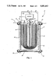
- FIG. 1 is a partially exploded, fragmentary, simplified schematic view of a system for the formation of bipolar electrodes according to a typical embodiment of the present invention.
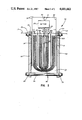
- FIG. 2 is a partially exploded fragmentary view of a simplified schematic of a system for the formation of electrodes according to an alternative embodiment of the present invention.
- a system 10 useful in the formation of electrodes for use in electrochemical cells is shown.
- the system generally designated 10, includes a pair of conductive end or counter electrodes 12 and 14 spaced apart from one another and disposed in an aqueous electrolyte 16 during operation of the system 10.
- the entire system 10 is placed in a bath (not shown) of aqueous electrolyte 16 with the level of electrolyte represented by the line 17.
- the end electrodes 12 and 14 are made of nickel foil and the electrolyte 16 may be an aqueous solution of the hydroxide of an alkali metal, e.g., NaOH, KOH or LiOH, with KOH being preferred and KOH of a concentration of about 30-45 wt % being especially preferred.
- an alkali metal e.g., NaOH, KOH or LiOH
- KOH being preferred
- KOH of a concentration of about 30-45 wt % being especially preferred.
- different electrolytes and/or different concentrations of electrolyte may be preferred. However, selection of specific electrolytes and concentrations will be within the skill of those in the art, guided by the teachings herein.
- each of the illustrated precursor electrodes 20 and 22 comprises porous elemental silver as the material 24 bonded to a bi-metal silver clad nickel foil substrate 26.
- the nickel foil substrate 26 is plated with silver so as to facilitate adherence of elemental silver thereto.
- the efficiency of the oxidation/reduction process is increased by minimizing and/or eliminating the areas of the substrates 26 that are in direct mechanical contact with the aqueous electrolyte 16, i.e., decreasing or eliminating the substrate/electrolyte interface at which, as described above, the release of oxygen is thermodynamically favored.
- the process of the invention results in the production of electrodes having a higher, more uniform charge capacity.
- the precursor electrodes 20 and 22 are placed in register and in a configuration wherein the substrate 26 of the first precursor electrode 20 is aligned and in contact with the substrate 26 of the second precursor electrode 22. This positioning of the precursor electrodes 20 and 22 substantially precludes contact between the electrolyte 16 and the substrates 26 of the precursor electrodes 20 and 22, and thereby increases the efficiency of the reduction/oxidation process.
- the end electrodes 12 and 14 and the substrates 26 of the precursor electrodes 20 and 22 are in electrical contact with a power supply such as a battery 27 so as to effect ionic current flow in the aqueous electrolyte 16 whereby the material 24 of the precursor electrodes 20 and 22 is reduced or oxidized.
- a power supply such as a battery 27
- the charge flow in the electrolyte 16 is generally away from the end electrodes 12 and 14 and toward the precursor electrodes 20 and 22, i.e., toward the substrates 26.
- the electrical wiring 28 connects the substrates 26 with the positive terminal 29 of the battery 27 (the end electrodes 12 and 14 are connected by the electrical wiring 30 with the negative terminal 31 of the battery 27).
- a restraining means such as restraining plates 32 and restraining nuts 33 and bolts 34 are included in system 10.
- the restraining plates 32, nuts 33 and bolts 34 serve to apply restraining forces to the previously described configuration of the end electrodes 12 and 14 and the precursor electrodes 20 and 22. These restraining forces substantially maintain the dimensions of the precursor electrodes 20 and 22 notwithstanding the volumetric changes in the material 24 attendant the reduction or oxidation thereof.
- the restraining forces as applied to precursor electrodes disposed in the above-described back-to-back configuration serve to maintain direct contact between the substrates 26 of the precursor electrodes 20 and 22.
- the restraining forces serve to further reduce and minimize the possibility of electrolyte seeping between the precursor electrodes 20 and 22 and coming into direct contact with either of the substrates 26.
- these restraining forces are not of a magnitude sufficient to harm or destroy the structure of the material 24 to be reduced or oxidized.
- a tension of about 40 inch pounds has been found to be effective to maintain the substrates of the precursor electrodes in direct contact without harming the structure of the elemental silver of the precursor electrodes.
- a wetting or wicking separator material 36 Disposed between the precursor electrodes 20 and 22 and the end electrodes 12 and 14 is a wetting or wicking separator material 36 which permits the aqueous electrolyte 16 to come in contact with the material 24 of each of the precursor electrodes 20 and 22.
- the separator material 36 is in an amount effective to allow the restraining forces produced by the action of the restraining plates 32 in conjunction with the nuts 33 and the bolts 34 to be substantially uniformly applied to the precursor electrodes 20 and 22.
- VEXAR a plastic screen material exemplified by "VEXAR" (a trademark of E. I. DuPont de Nemours and Co. for a polypropylene plastic screen material) has effectively been used as the separator 36.
- the solid plastic parts of the "VEXAR" plastic screen transmit the mechanical force being applied thereto while the openings in the screen permit the electrolyte to come in contact with the material 24 of the precursor electrode 20 and 22.
- electrodes By effecting ionic charge flow through the aqueous electrolyte 16 in the above-described system 10, electrodes having desired degrees of flatness, integrity, weight gain, color uniformity, thickness and density uniformity are formed. Furthermore, the rejection rate of electrodes so formed is reduced.
- a system, generally designated 50, similar to the system 10 of FIG. 1 is shown.
- the system 50 includes components such as a pair of conductive end electrodes 12 and 14, a pair of precursor electrodes 20 and 22, a power supply 27, restraining plates 32, an effective amount of a wetting or wicking separator material 36 and associated connections.
- the system 50 includes a semi-permeable membrane 52 disposed between each of the end electrodes 12 and 14 and the precursor electrodes 20 and 22.
- the wicking separator, designated 36A and 36B, respectively, is disposed between the membrane 52 and each of the end electrodes 12 and 14 and the membrane 52 and each of the precursor electrodes 20 and 22. It is to be understood, however, that other membrane/separator/electrode configurations will be within the skill of those in the art, guided by the teachings herein.
- the membrane 52 is effective in preventing migration of the material 24 to be reduced or oxidized, from the precursor electrodes 20 and 22 to the end electrodes 12 and 14, while permitting ionic charge transport therebetween.
- Semi-permeable membrane materials effective in preventing migration of silver include cellophane (manufactured by DuPont), silver treated cellophane, referred to as C19, available from Yardney Electric Co. or the preferred fibrous sausage casing (designated FSC) sold by Union Carbide Corp.
- the C19 or other cellulose base separators are allowed to absorb the electrolyte to facilitate the transport of ionic charge therethrough during operation of the system.
- Two sets of back-to-back 11 inch diameter silver bipolar precursor electroplates were placed in an aqueous solution of potassium hydroxide (about 35 wt % potassium hydroxide) as shown in FIG. 1.
- the plates were placed in register so as to minimize the nickel/electrolyte interfacial area.
- a separator of "VEXAR" polypropylene screen material is placed about the outer silver surfaces of the precursor electrodes.
- Restraining plates are placed on either side of the pair of back-to-back precursor electrodes and tightened to finger tightness (on the order of 5 inch pounds of torque) so as to maintain the dimensions of the electrode during charge and to maintain the metal to metal contact of each of the precursor electrode pairs.
- the charge rate was decreased to 1.8A per plate from the previously used value of 2.15A per plate.
- the charge time was decreased from 60 hours to 43 hours and the voltage at the end of charge was about 1.7 volts instead of 1.9+ volts per cell. Further, no plates were rejected whereas previous runs, not utilizing the method of the present invention, resulted in rejection rates of between 50 and 100%.
- Restraining plates were placed on either side of this arrangement to maintain the above-described system under a tension of 10, and later 40, inch pounds.
- the system was then placed in a tank of aqueous potassium hydroxide electrolyte (about 35 wt % potassium hydroxide) and allowed to equilibrate with the electrolyte. (C19 and other cellulose separators require a period of time to imbibe the electrolyte.)
Landscapes
- Chemical & Material Sciences (AREA)
- Chemical Kinetics & Catalysis (AREA)
- Electrochemistry (AREA)
- General Chemical & Material Sciences (AREA)
- Engineering & Computer Science (AREA)
- Manufacturing & Machinery (AREA)
- Battery Electrode And Active Subsutance (AREA)
- Cell Electrode Carriers And Collectors (AREA)
Abstract
Description
2Ag+2OH.sup.- →Ag.sub.2 O+H.sub.2 O+2e.sup.- ( 1)
Ag.sub.2 O+2OH.sup.- →2AgO+H.sub.2 O+2e.sup.- ( 2A)
Ag+2OH.sup.- →AgO+H.sub.2 O+2e.sup.- ( 2B)
Claims (44)
Priority Applications (3)
| Application Number | Priority Date | Filing Date | Title |
|---|---|---|---|
| US06/941,204 US4681663A (en) | 1986-12-12 | 1986-12-12 | Bipolar electrode formation |
| PCT/US1987/003250 WO1988004477A1 (en) | 1986-12-12 | 1987-12-07 | Bipolar electrode formation |
| EP19880900328 EP0299990A4 (en) | 1986-12-12 | 1987-12-07 | Bipolar electrode formation. |
Applications Claiming Priority (1)
| Application Number | Priority Date | Filing Date | Title |
|---|---|---|---|
| US06/941,204 US4681663A (en) | 1986-12-12 | 1986-12-12 | Bipolar electrode formation |
Publications (1)
| Publication Number | Publication Date |
|---|---|
| US4681663A true US4681663A (en) | 1987-07-21 |
Family
ID=25476094
Family Applications (1)
| Application Number | Title | Priority Date | Filing Date |
|---|---|---|---|
| US06/941,204 Expired - Fee Related US4681663A (en) | 1986-12-12 | 1986-12-12 | Bipolar electrode formation |
Country Status (3)
| Country | Link |
|---|---|
| US (1) | US4681663A (en) |
| EP (1) | EP0299990A4 (en) |
| WO (1) | WO1988004477A1 (en) |
Cited By (4)
| Publication number | Priority date | Publication date | Assignee | Title |
|---|---|---|---|---|
| US4851310A (en) * | 1987-09-18 | 1989-07-25 | Gould Inc. | Microporous elemental silver article and method |
| US4913782A (en) * | 1987-09-18 | 1990-04-03 | Gould Inc. | Microporous elemental silver article and method |
| US4913781A (en) * | 1987-09-18 | 1990-04-03 | Gould Inc. | Microporous elemental silver and method |
| EP1071151A1 (en) * | 1999-07-23 | 2001-01-24 | Nec Corporation | Method for producing film packed battery |
Citations (1)
| Publication number | Priority date | Publication date | Assignee | Title |
|---|---|---|---|---|
| US4269907A (en) * | 1980-05-05 | 1981-05-26 | Lockheed Missiles & Space Company, Inc. | Electrochemical cell |
Family Cites Families (3)
| Publication number | Priority date | Publication date | Assignee | Title |
|---|---|---|---|---|
| BE486697A (en) * | 1946-04-11 | |||
| DE1143876B (en) * | 1955-03-11 | 1963-02-21 | Svenska Ackumulator Ab | Alkaline silver-zinc accumulator cell |
| US4704194A (en) * | 1986-07-28 | 1987-11-03 | Gould Inc. | Electrode formation |
-
1986
- 1986-12-12 US US06/941,204 patent/US4681663A/en not_active Expired - Fee Related
-
1987
- 1987-12-07 EP EP19880900328 patent/EP0299990A4/en not_active Withdrawn
- 1987-12-07 WO PCT/US1987/003250 patent/WO1988004477A1/en not_active Ceased
Patent Citations (1)
| Publication number | Priority date | Publication date | Assignee | Title |
|---|---|---|---|---|
| US4269907A (en) * | 1980-05-05 | 1981-05-26 | Lockheed Missiles & Space Company, Inc. | Electrochemical cell |
Cited By (5)
| Publication number | Priority date | Publication date | Assignee | Title |
|---|---|---|---|---|
| US4851310A (en) * | 1987-09-18 | 1989-07-25 | Gould Inc. | Microporous elemental silver article and method |
| US4913782A (en) * | 1987-09-18 | 1990-04-03 | Gould Inc. | Microporous elemental silver article and method |
| US4913781A (en) * | 1987-09-18 | 1990-04-03 | Gould Inc. | Microporous elemental silver and method |
| EP1071151A1 (en) * | 1999-07-23 | 2001-01-24 | Nec Corporation | Method for producing film packed battery |
| US6558438B1 (en) | 1999-07-23 | 2003-05-06 | Nec Corporation | Method for producing a pressurized package for a film packed battery |
Also Published As
| Publication number | Publication date |
|---|---|
| EP0299990A4 (en) | 1990-04-10 |
| WO1988004477A1 (en) | 1988-06-16 |
| EP0299990A1 (en) | 1989-01-25 |
Similar Documents
| Publication | Publication Date | Title |
|---|---|---|
| US3532548A (en) | Electrochemical cell utilizing three electrodes | |
| US6228527B1 (en) | Magnesium solution phase catholyte seawater electrochemical system | |
| US4126733A (en) | Electrochemical generator comprising an electrode in the form of a suspension | |
| CA1143432A (en) | Redox process and accumulator | |
| US5166011A (en) | Process for forming an argentic oxide containing bipolar electrode and product produced thereby and deferred actuated battery assembly employing same | |
| EP0290764A1 (en) | Cylindrical bipolar electrode battery | |
| US3770505A (en) | Multicell battery comprising duplex electrode utilizing conductive plastic carrier strip | |
| US3713892A (en) | Method of charging secondary metal-air cell | |
| US3560262A (en) | Electrode with a non-woven fabric base and electroplated coatings of nickel | |
| US3749608A (en) | Primary electrochemical energy cell | |
| US5532087A (en) | Electrochemical cell | |
| US3540935A (en) | Alkaline secondary battery and electrolyte therefor | |
| US4677041A (en) | Electrode assemblies for electrochemical cells | |
| US4681663A (en) | Bipolar electrode formation | |
| US4140589A (en) | Method for lead crystal storage cells and storage devices made therefrom | |
| US3784410A (en) | Battery with duplex electrode construction using continuous metal carrier strip having at least one nonreactive metal side | |
| US4704194A (en) | Electrode formation | |
| US3694266A (en) | Method of assembling multicell batteries comprising duplex electrode construction using continuous electrically conductive plastic carrier strip | |
| JP2743416B2 (en) | Zinc plate for rechargeable batteries | |
| JP2001189156A (en) | Battery electrode and battery | |
| US3573987A (en) | Electrochemical electric power generator | |
| US3697328A (en) | Duplex electrode construction using continuous metal carrier strip coated on one side with conductive adhesive | |
| US3706616A (en) | Duplex electrode construction using continuous metal carrier strip having at least one nonreactive metal side | |
| US4913782A (en) | Microporous elemental silver article and method | |
| JPH0765821A (en) | Lead storage battery |
Legal Events
| Date | Code | Title | Description |
|---|---|---|---|
| AS | Assignment |
Owner name: GOULD INC., 10 GOULD CENTER, ROLLING MEADOWS, IL 6 Free format text: ASSIGNMENT OF ASSIGNORS INTEREST.;ASSIGNOR:SEIGER, HARVEY N.;REEL/FRAME:004675/0223 Effective date: 19861210 |
|
| AS | Assignment |
Owner name: WESTINGHOUSE ELECTRIC CORPORATION, WESTINGHOUSE BU Free format text: ASSIGNMENT OF ASSIGNORS INTEREST.;ASSIGNOR:GOULD INC.;REEL/FRAME:004883/0758 Effective date: 19880329 |
|
| FPAY | Fee payment |
Year of fee payment: 4 |
|
| FEPP | Fee payment procedure |
Free format text: PAYOR NUMBER ASSIGNED (ORIGINAL EVENT CODE: ASPN); ENTITY STATUS OF PATENT OWNER: LARGE ENTITY |
|
| FPAY | Fee payment |
Year of fee payment: 8 |
|
| AS | Assignment |
Owner name: NORTHROP GRUMMAN CORPORATION, CALIFORNIA Free format text: ASSIGNMENT OF ASSIGNORS INTEREST;ASSIGNOR:WESTINGHOUSE ELECTRIC CORPORATION;REEL/FRAME:008104/0190 Effective date: 19960301 |
|
| REMI | Maintenance fee reminder mailed | ||
| LAPS | Lapse for failure to pay maintenance fees | ||
| FP | Lapsed due to failure to pay maintenance fee |
Effective date: 19990721 |
|
| STCH | Information on status: patent discontinuation |
Free format text: PATENT EXPIRED DUE TO NONPAYMENT OF MAINTENANCE FEES UNDER 37 CFR 1.362 |