US4680439A - Plastic microwave oven cavity - Google Patents
Plastic microwave oven cavity Download PDFInfo
- Publication number
- US4680439A US4680439A US06/869,214 US86921486A US4680439A US 4680439 A US4680439 A US 4680439A US 86921486 A US86921486 A US 86921486A US 4680439 A US4680439 A US 4680439A
- Authority
- US
- United States
- Prior art keywords
- microwave
- side wall
- assembly
- wall member
- cavity
- Prior art date
- Legal status (The legal status is an assumption and is not a legal conclusion. Google has not performed a legal analysis and makes no representation as to the accuracy of the status listed.)
- Expired - Fee Related
Links
Images


Classifications
-
- H—ELECTRICITY
- H05—ELECTRIC TECHNIQUES NOT OTHERWISE PROVIDED FOR
- H05B—ELECTRIC HEATING; ELECTRIC LIGHT SOURCES NOT OTHERWISE PROVIDED FOR; CIRCUIT ARRANGEMENTS FOR ELECTRIC LIGHT SOURCES, IN GENERAL
- H05B6/00—Heating by electric, magnetic or electromagnetic fields
- H05B6/64—Heating using microwaves
- H05B6/6426—Aspects relating to the exterior of the microwave heating apparatus, e.g. metal casing, power cord
Definitions
- microwave oven cavities from sheet matal parts.
- the cavity of the microwave oven was typically made up of such sheet metal into a generally box-shaped structure having one side substantially open for access in inserting and retrieving food when the access door was open.
- Such sheet metal structures have been relatively expensive and difficult to manufacture.
- post-forming treatment such as painting to provide for an aesthetically pleasing interior surface which was at the same time required to be hygienic because microwave ovens are used to prepare food.
- the present invention overcomes the shortcomings of the sheet metal microwave oven cavity construction by providing a plastic microwave oven cavity assembly formed of top and bottom members having a microwave impermeable coating on the interior thereof and a side wall member having a microwave impermeable coating on the exterior thereof with the members joined by seams which maintain the integrity of the microwave impermeable coating to contain microwave energy within the cavity.
- a front wall also formed of coated plastic provides the access aperture and continues the microwave impermeable coating to the periphery of the access aperture.
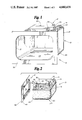
- FIG. 1 shows a perspective view of the completed assembly of a microwave oven cavity, front panel and shelf.
- FIG. 2 shows a side perspective view of the cavity assembly with the front panel removed.
- FIG. 3 shows a perspective view of the back surface of the front panel.
- FIG. 4 shows an exploded view of the top, side wall, shelf and bottom members of the plastic microwave oven cavity.
- FIG. 5 shows a fragmented perspective view of the seams joining the top and bottom members to the side wall member.
- FIG. 6 shows an exploded view of details of the elements which form the seam between the side wall and bottom members.
- a plastic microwave oven cavity 10 is shown assembled to a plastic microwave oven front panel 12.
- a seam 14 joins a generally pan-shaped top member 16 to a generally U-shaped side wall member 18.
- a seam 20 joins side wall member 18 to a generally pan-shaped bottom member 22 (not visible in FIG. 1).
- a shelf member 24 is provided to function as a floor of the microwave oven cooking cavity and is preferably made of microwave transparent material. Shelf 24 may be permanently affixed to cavity 10 or may be made removable.
- pan-shaped top member 16 preferably has a stirrer box 26 integrally formed therein.
- stirrer box 26 is shown in rectangular form in the figures, other shapes such as cylinders or arbitrary shapes may be found desirable.
- Stirrer box 26 may have a waveguide or other microwave communication passageway 28 formed integrally therewith.
- Waveguide 28 may have a cross section other than rectangular if desired.
- a conventional waveguide flange 30 is shown at the end of waveguide 28, however, other configurations to couple the waveguide or other communication passageway for microwaves between the stirrer box and the source of microwave energy are contemplated.
- It may be found desirable to include one or more groups of apertures 32 in the feed box to provide passageways for air flow into or out of feedbox 26.
- one or more aperture groups may be included in side wall member 18 for communication of air or light to the interior of the cavity.
- FIGS. 2 and 3 a partially exploded view of cavity 10 and front panel 12 may be seen, showing more details of panel 12.
- panel 12 has a flange 34 surrounding the cavity access aperture 36.
- a front surface 38 of panel 12, seen most clearly in FIG. 1 is preferably flat for purposes of aesthetics and for providing a surface to cooperate with a microwave oven door to seal the energy in the cavity.
- a back surface 40 of front panel 12 similarly is generally planar.
- Flange 34 projecting substantially perpendicularly from back surface 40 preferably has a plurality of box-like portions 42 to accomodate the ends 44 of seams 14, 20.
- Panel 12 may also have a second flange or lip 35 parallel to the top portion 37 of flange 34. Lip 35 is spaced from portion 37 a distance to closely engage front edge 17 of top member 16. A similar lip may be provided on panel 12 for bottom member 22. Alternatively, as shown in FIG. 2, lips 35 may be omitted.
- Members 16 and 22 preferably have grooves 46, 48 respectively, extending around a portion of their peripheries.
- Members 18 preferably has tongue portions 50, 52 extending about a corresponding portion of the periphery of the side wall member designed to mate with respective grooves 46, 48.
- the speckled shading indicates a coating on the plastic pieces which is impermeable to microwave energy.
- the coating is on the exterior of member 18, and on the interior of members 16 and 22.
- the coating is preferably within the flange of member 12 and may extend to either of front surface 38 or back surface 40 of front panel 12. If one or two lips 35 are provided, the coating is preferably extended to the groove formed by lip 35 and portion 37. It has been found desirable to place the microwave impermeable coating on the exterior of the side wall member to protect the coating from contact from within the microwave oven cavity during use to avoid abrasion and possible impairment of the microwave containment function of the coating.
- Members 16 and 22 may be coated on the interior surfaces since this microwave oven cavity construction provides for additional layers of material such as shelf 24 and cover member 25 to protect the microwave impermeable coating on members 16 and 22 from contact during microwave oven use.
- the microwave impermeable coating may be formed by utilizing the series 4700 tie coat (bond coat) and the 02Z arc spray zinc from TAFA, Inc., Dow Road, Bow, N.H. 03301-1157.
- a copper or nickel arc sprayed coating or another microwave impermeable coating, such as metallic paint or conductive ink may be utilized.
- the microwave impermeable coating is shown as speckled shading 54 in FIG. 5 and as a heavy margin line 54 in FIG. 6.
- tongue 52 When tongue 52 is inserted into groove 48 the microwave impermeable coating is connected throughout seam 20 to prevent the escape of microwave energy from the interior of the microwave oven cavity.
- Joining tongue 50 to groove 46 results in a similar continuously microwave impermeable surface.
- Joining front panel 12 to cavity 10 extends the microwave impermeable surface to the region of the periphery of the cavity access aperture 36. Lip 35 may be utilized to maintain continuity of the coating between edge 17 of top member 16 and the top portion 37 of flange 34.
- Seam 14 is illustrated with optional transverse interruptions 56 in the portion forming groove 46. This results in individual fingers forming one side of groove 46 and will provide a more even load distrubution in the event of width irregularities in tongue 50.
- Seams 14, 20 and 21 may be secured by an appropriate adhesive or an "interfering" geometry for the mating surfaces such as matching indentations and projections or by frictional engagement. Still further alternatives are to provide separate fastening elements such as pins extending through the tongue and groove of seams 14 and 20 or to provide for appropriate geometries suitable for plastic welding or staking techniques.
Abstract
Description
Claims (8)
Priority Applications (1)
| Application Number | Priority Date | Filing Date | Title |
|---|---|---|---|
| US06/869,214 US4680439A (en) | 1986-05-30 | 1986-05-30 | Plastic microwave oven cavity |
Applications Claiming Priority (1)
| Application Number | Priority Date | Filing Date | Title |
|---|---|---|---|
| US06/869,214 US4680439A (en) | 1986-05-30 | 1986-05-30 | Plastic microwave oven cavity |
Publications (1)
| Publication Number | Publication Date |
|---|---|
| US4680439A true US4680439A (en) | 1987-07-14 |
Family
ID=25353128
Family Applications (1)
| Application Number | Title | Priority Date | Filing Date |
|---|---|---|---|
| US06/869,214 Expired - Fee Related US4680439A (en) | 1986-05-30 | 1986-05-30 | Plastic microwave oven cavity |
Country Status (1)
| Country | Link |
|---|---|
| US (1) | US4680439A (en) |
Cited By (7)
| Publication number | Priority date | Publication date | Assignee | Title |
|---|---|---|---|---|
| US4912741A (en) * | 1987-07-31 | 1990-03-27 | Matsushita Electric Industrial Co., Ltd. | Heating box for a microwave oven |
| US5017750A (en) * | 1989-04-25 | 1991-05-21 | Sharp Kabushiki Kaisha | Frame construction for microwave oven having an integrally formed open chassis and an inserting opening |
| US5442161A (en) * | 1992-09-30 | 1995-08-15 | Matsushita Electric Industrial Co., Ltd. | Oven having vacuum heat insulating wall and method for assembling same |
| EP0905452A1 (en) * | 1996-05-31 | 1999-03-31 | Matsushita Electric Industrial Co., Ltd. | High-frequency cooker and method of manufacturing the same |
| WO2001026815A1 (en) * | 1999-10-08 | 2001-04-19 | Moats William A | Microwave heated centrifugal vacuum concentrator |
| US20060027570A1 (en) * | 1999-04-22 | 2006-02-09 | California Institute Of Technology, A Corporation | Microwave bonding of MEMS component |
| EP1940200A1 (en) * | 2006-12-27 | 2008-07-02 | FagorBrandt SAS | Microwave oven comprising a cavity and a wave guide using a material designed to be enamelled at a high temperature |
Citations (2)
| Publication number | Priority date | Publication date | Assignee | Title |
|---|---|---|---|---|
| US4385082A (en) * | 1981-03-11 | 1983-05-24 | General Electric Company | Preparation of shielded plastic microwave oven |
| US4563559A (en) * | 1982-12-27 | 1986-01-07 | Enami Seiki Mfg. Co., Ltd. | Inner box for a cooking appliance |
-
1986
- 1986-05-30 US US06/869,214 patent/US4680439A/en not_active Expired - Fee Related
Patent Citations (2)
| Publication number | Priority date | Publication date | Assignee | Title |
|---|---|---|---|---|
| US4385082A (en) * | 1981-03-11 | 1983-05-24 | General Electric Company | Preparation of shielded plastic microwave oven |
| US4563559A (en) * | 1982-12-27 | 1986-01-07 | Enami Seiki Mfg. Co., Ltd. | Inner box for a cooking appliance |
Non-Patent Citations (13)
| Title |
|---|
| Acheson Polymer Thick Film Inks Information Sheet, 23 pgs. no publication date. * |
| Bond Coat Prepares Plastic for Metallizing pp. 114 and 115, Design News 5 6 85. * |
| Bond Coat Prepares Plastic for Metallizing--pp. 114 and 115, Design News 5-6-85. |
| TAFA Application Data File 2.4.3.11 30 Attenuation of TAFA Zink Coatings, Jan. 1979, 4 pgs. * |
| TAFA Application Data File 2.4.3.11-30 Attenuation of TAFA Zink Coatings, Jan. 1979, 4 pgs. |
| TAFA Application Data file 2.4.3.12 Thick Zinc and Copper Zinc Coatings on Thin Plastic, Jan. 1979, one page. * |
| TAFA Application Data file 2.4.3.12--Thick Zinc and Copper Zinc Coatings on Thin Plastic, Jan. 1979, one page. |
| TAFA Application Data file 2.4.3.13 Shielding Background Data, Apr. 1979, 2 pgs. * |
| TAFA Application Data file 2.4.3.13-Shielding Background Data, Apr. 1979, 2 pgs. |
| TAFA Application Data File 2.4.3.14.2 Typical Specification: TAFA Tiecoat/Arc Spray Metalized Zinc Coating on Plastic Substrates, Nov. 1984, 3 pgs. * |
| TAFA Application Data File 2.4.3.14.2--Typical Specification: TAFA Tiecoat/Arc Spray Metalized Zinc Coating on Plastic Substrates, Nov. 1984, 3 pgs. |
| TAFA Technical Data File 1.9.4.4.2 TAFA Tiecoat A Bond Coat for Plastics 11 1984, 6 pgs. * |
| TAFA Technical Data File 1.9.4.4.2--TAFA Tiecoat--A Bond Coat for Plastics--11-1984, 6 pgs. |
Cited By (10)
| Publication number | Priority date | Publication date | Assignee | Title |
|---|---|---|---|---|
| US4912741A (en) * | 1987-07-31 | 1990-03-27 | Matsushita Electric Industrial Co., Ltd. | Heating box for a microwave oven |
| US5017750A (en) * | 1989-04-25 | 1991-05-21 | Sharp Kabushiki Kaisha | Frame construction for microwave oven having an integrally formed open chassis and an inserting opening |
| US5442161A (en) * | 1992-09-30 | 1995-08-15 | Matsushita Electric Industrial Co., Ltd. | Oven having vacuum heat insulating wall and method for assembling same |
| EP0905452A1 (en) * | 1996-05-31 | 1999-03-31 | Matsushita Electric Industrial Co., Ltd. | High-frequency cooker and method of manufacturing the same |
| EP0905452A4 (en) * | 1996-05-31 | 2000-03-15 | Matsushita Electric Ind Co Ltd | High-frequency cooker and method of manufacturing the same |
| US6191403B1 (en) * | 1996-05-31 | 2001-02-20 | Matsushita Electric Industrial Co., Ltd. | High frequency heating cooking apparatus and manufacturing method thereof |
| US20060027570A1 (en) * | 1999-04-22 | 2006-02-09 | California Institute Of Technology, A Corporation | Microwave bonding of MEMS component |
| WO2001026815A1 (en) * | 1999-10-08 | 2001-04-19 | Moats William A | Microwave heated centrifugal vacuum concentrator |
| EP1940200A1 (en) * | 2006-12-27 | 2008-07-02 | FagorBrandt SAS | Microwave oven comprising a cavity and a wave guide using a material designed to be enamelled at a high temperature |
| FR2911037A1 (en) * | 2006-12-27 | 2008-07-04 | Brandt Ind Sas | MICROWAVE OVEN COMPRISING A CAVITY AND A WAVEGUIDE USING A MATERIAL FOR HIGH TEMPERATURE ENAMEL |
Similar Documents
| Publication | Publication Date | Title |
|---|---|---|
| US4680439A (en) | Plastic microwave oven cavity | |
| USD369269S (en) | Mini cooking center | |
| US5568712A (en) | Refrigerator door construction | |
| USD386938S (en) | Electric toaster oven | |
| USD369717S (en) | Mold for baking cake in microwave oven | |
| USD482661S1 (en) | Cover for an electrical receptacle | |
| USD354415S (en) | Microwave oven | |
| USD353074S (en) | Microwave oven | |
| USD353512S (en) | Microwave oven | |
| USD358291S (en) | Electric oven bakery | |
| USD371039S (en) | Microwave oven | |
| USD277204S (en) | Toy stove or similar article | |
| USD364311S (en) | Microwave oven | |
| USD409437S (en) | Microwave oven | |
| USD381862S (en) | Microwave oven | |
| USD412083S (en) | Microwave oven | |
| USD368405S (en) | Microwave oven | |
| USD367992S (en) | Microwave oven | |
| USD387241S (en) | Microwave oven | |
| USD380340S (en) | Microwave oven | |
| USD410814S (en) | Microwave oven | |
| USD411706S (en) | Microwave oven | |
| USD401470S (en) | Microwave oven | |
| USD366591S (en) | Microwave oven | |
| USD387609S (en) | Microwave oven |
Legal Events
| Date | Code | Title | Description |
|---|---|---|---|
| AS | Assignment |
Owner name: LITTON SYSTEMS, INC., 360 N. CRESCENT DRIVE, BEVER Free format text: ASSIGNMENT OF ASSIGNORS INTEREST.;ASSIGNOR:MILLMAN, RONALD W.;REEL/FRAME:004561/0475 Effective date: 19860530 Owner name: LITTON SYSTEMS, INC., CALIFORNIA Free format text: ASSIGNMENT OF ASSIGNORS INTEREST;ASSIGNOR:MILLMAN, RONALD W.;REEL/FRAME:004561/0475 Effective date: 19860530 |
|
| FEPP | Fee payment procedure |
Free format text: PAYOR NUMBER ASSIGNED (ORIGINAL EVENT CODE: ASPN); ENTITY STATUS OF PATENT OWNER: LARGE ENTITY |
|
| FPAY | Fee payment |
Year of fee payment: 4 |
|
| AS | Assignment |
Owner name: AMANA REFRIGERATION INC., IOWA Free format text: ASSIGNMENT OF ASSIGNORS INTEREST;ASSIGNORS:LITTON SYSTEMS, INC., A CORP. OF DE AND ITS WHOLLY-OWNED DIRECT AND INDIRECT SUBSIDIARIES AMERICAN COOKING PRODUCTS INC. AND MENUMASTER, INC.;MENUMASTER INC., A CORP OF NV;REEL/FRAME:006638/0067 Effective date: 19930716 |
|
| REMI | Maintenance fee reminder mailed | ||
| LAPS | Lapse for failure to pay maintenance fees | ||
| FP | Lapsed due to failure to pay maintenance fee |
Effective date: 19950719 |
|
| STCH | Information on status: patent discontinuation |
Free format text: PATENT EXPIRED DUE TO NONPAYMENT OF MAINTENANCE FEES UNDER 37 CFR 1.362 |