US4678372A - Raising method and device, in particular for an oil exploiting platform - Google Patents
Raising method and device, in particular for an oil exploiting platform Download PDFInfo
- Publication number
- US4678372A US4678372A US06/894,120 US89412086A US4678372A US 4678372 A US4678372 A US 4678372A US 89412086 A US89412086 A US 89412086A US 4678372 A US4678372 A US 4678372A
- Authority
- US
- United States
- Prior art keywords
- leg
- raising
- platform
- legs
- raising device
- Prior art date
- Legal status (The legal status is an assumption and is not a legal conclusion. Google has not performed a legal analysis and makes no representation as to the accuracy of the status listed.)
- Expired - Lifetime
Links
- 238000000034 method Methods 0.000 title claims abstract description 16
- 238000005520 cutting process Methods 0.000 claims abstract description 8
- 230000003014 reinforcing effect Effects 0.000 claims abstract description 7
- 238000003466 welding Methods 0.000 claims description 8
- 239000003921 oil Substances 0.000 description 12
- 239000002184 metal Substances 0.000 description 4
- 238000006073 displacement reaction Methods 0.000 description 3
- 230000000295 complement effect Effects 0.000 description 2
- 239000012530 fluid Substances 0.000 description 2
- 238000009877 rendering Methods 0.000 description 2
- 239000000725 suspension Substances 0.000 description 2
- 229910000831 Steel Inorganic materials 0.000 description 1
- 238000004891 communication Methods 0.000 description 1
- 238000007596 consolidation process Methods 0.000 description 1
- 238000010276 construction Methods 0.000 description 1
- 230000007423 decrease Effects 0.000 description 1
- 238000009434 installation Methods 0.000 description 1
- 239000000346 nonvolatile oil Substances 0.000 description 1
- 238000002360 preparation method Methods 0.000 description 1
- 238000005086 pumping Methods 0.000 description 1
- 125000006850 spacer group Chemical group 0.000 description 1
- 239000010959 steel Substances 0.000 description 1
Images


Classifications
-
- E—FIXED CONSTRUCTIONS
- E02—HYDRAULIC ENGINEERING; FOUNDATIONS; SOIL SHIFTING
- E02B—HYDRAULIC ENGINEERING
- E02B17/00—Artificial islands mounted on piles or like supports, e.g. platforms on raisable legs or offshore constructions; Construction methods therefor
-
- E—FIXED CONSTRUCTIONS
- E02—HYDRAULIC ENGINEERING; FOUNDATIONS; SOIL SHIFTING
- E02B—HYDRAULIC ENGINEERING
- E02B17/00—Artificial islands mounted on piles or like supports, e.g. platforms on raisable legs or offshore constructions; Construction methods therefor
- E02B17/04—Equipment specially adapted for raising, lowering, or immobilising the working platform relative to the supporting construction
- E02B17/08—Equipment specially adapted for raising, lowering, or immobilising the working platform relative to the supporting construction for raising or lowering
- E02B17/0809—Equipment specially adapted for raising, lowering, or immobilising the working platform relative to the supporting construction for raising or lowering the equipment being hydraulically actuated
-
- E—FIXED CONSTRUCTIONS
- E02—HYDRAULIC ENGINEERING; FOUNDATIONS; SOIL SHIFTING
- E02B—HYDRAULIC ENGINEERING
- E02B17/00—Artificial islands mounted on piles or like supports, e.g. platforms on raisable legs or offshore constructions; Construction methods therefor
- E02B2017/0052—Removal or dismantling of offshore structures from their offshore location
Definitions
- the present invention relates to oil platforms and more particularly to the raising of offshore oil exploiting platforms.
- the sinking of the site results in a subsidence of the sea bed on which the pylons of the oil exploiting platforms bear so that their height above the sea level decreases dangerously and there is a risk of rendering these platforms dangerous within a few years for the exploiting personnel, especially in bad weather.
- An object of the invention is to provide a method and a device for raising an oil platform to a sufficient height to enable the platform to be used, notwithstanding the sinking of the sea bed on which it is placed, until the exhaustion of the oil-bearing strata it exploits.
- the invention therefore provides a method for raising an offshore oil exploiting platform comprising a platform proper or deck carried by legs which bear on the sea bed, said method comprising:
- FIG. 1 is a diagrammatic elevational view of an oil platform before it is raised by means of the method of the invention
- FIG. 2 is a view similar to FIG. 1 of the platform after it has been raised;
- FIG. 3 is a partial elevational view to an enlarged scale of an oil platform leg on which is mounted a raising device according to the invention before the raising;
- FIG. 4 is a view corresponding to that of FIG. 3 showing the raising device according to the invention in the position at the end of the raising;
- FIG. 5 is a partial view to an enlarged scale of an oil platform leg showing a first stage of the raising method according to the invention
- FIG. 6 is a view similar to FIG. 5 showing a second stage of the raising method according to the invention.
- FIG. 7 is a view similar to FIGS. 5 and 6 showing the leg of the platform after raising
- FIGS. 8 and 9 are diagrammatic elevational views of the stages for placing in position the head of the raising device around a platform leg;
- FIGS. 10 to 12 are views similar to FIGS. 8 and 9 showing the positioning of the supports of the raising device
- FIGS. 13 and 14 are diagrammatic views of the installation of the hydraulic jacks in the supports of the raising device
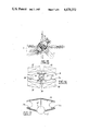
- FIG. 15 is a partial plan view of the intermediate support of the raising device in position on a platform leg
- FIG. 16 is a plan view of the intermediate support of the raising device according to the invention.
- FIG. 17 is a plan view of the lower support of the raising device according to the invention.
- FIG. 18 is a sectional view of a detail of the intermediate support.
- FIGS. 19 and 20 are diagrammatic elevational views showing the positioning of a heightening element constituting a spacer element after the raising of the platform.
- the platform diagrammatically shown in FIG. 1 comprises a platform proper or deck 1 supported by tubular legs 2 interconnected by a lattice 3 of metal girders and bearing on the sea bed.
- a raising device 4 Fixed to each of the legs 2 in a manner which will be described hereinafter is a raising device 4 constituted by an assembly of hydraulic jacks.
- the raising devices 4 are adapted, after the cutting of each of the legs in a region intermediate between the fixing regions of each of the raising devices on the leg 2 with which they are associated, to cooperate to ensure the upward displacement of the deck 1 through a suitable distance.
- FIG. 2 shows the platform of FIG. 1 after it has been raised. It can be seen that the raising devices 4 are in their extended position.
- heightening tubes 5 Interposed between the leg portions 2a and 2b resulting from the cutting of each of the legs 2, the ends of these portions being separated by a gap resulting from the raising operation, are heightening tubes 5 ensuring the reconstitution of the continuity of each of the legs.
- FIG. 3 There is shown to an enlarged scale in FIG. 3 a leg 2 of a platform on which is placed in position a raising device 4 constituted by two hydraulic jacks 6 whose cylinders 7 are interconnected by supports 8 and 9 welded to the leg 2 in regions located below the region of the leg which must be cut.
- the rods 10 of the jacks 6 bear through a head 11 welded below the lower part of the deck 1.
- the jacks 7 of the raising device 4 are shown in their retracted position. Between the first support 8 which assembles the upper ends of the cylinder 7 and the bearing head 11 of the rods 10 of the jacks there has been shown in dot-dash lines a region 12 in which the leg must be cut. Before proceeding to the cutting, the jacks 6 of the device 4 are put under load which then performs the function of a reinforcing device by taking the load exerted by the weight of the deck on the corresponding leg.
- the jacks 6 of the raising device 4 are shown in their extended position, the rods 10 of the jacks being in their outer position and having effected, through the bearing head 11 of their free ends, an upward displacement of the upper portion 2b of the leg 2, the lower portion 2a of the latter which bears on the sea bottom acting as a support through the supports 8 and 9 assembling the cylinders 7 of the jacks 6 when the raising effort is applied to the deck 1 by said jacks.
- the travel of the jack rods 10 corresponds to the extent to which the platform is raised. This raising extent is represented by the gap 13 resulting from the relative displacement of the portions 2a and 2b of the leg 2 after the latter has been cut in the region 12.
- FIGS. 5 to 7 in order to describe in more detail the various stages of the platform raising operation in respect of one of the legs of the platform.
- FIG. 5 shows a first stage of the operation during which, after the positioning of the raising device 4 and the communication of pressure to the jacks 6 of the latter, there has been cut in the leg 2 a tube section in the region 12 and this section has been removed so that the lower leg portion 2 and upper leg portion 2b are now separated by a gap.
- the portions 2a and 2b are held in position by the raising device which thus constitutes in the initial stage of the operations a device for reinforcing the leg 2.
- a connecting unit 14 is inserted between the upper portion 2a and lower portion 2b of the leg 2, this unit being in two parts provided with end flanges 15, 16 interconnected by assembly bolts 17.
- Each of the parts 15, 16 of the unit 14 is welded to the end of the corresponding portion 2a, 2b of the leg 2.
- the two parts 15, 16 of the unit 14 are provided with complementary centering cones (not shown) for, on one hand, centering the flanges relative to each other and, on the other hand, supporting the lateral forces.
- Such a technique permits proceeding in turn to the preparation of all the legs of the platform without compromising the stability of the latter, and, when all the legs have had a corresponding connecting unit 14 inserted therein, awaiting the suitable atmospheric conditions for proceeding to the raising proper, within a minimum period of time.
- FIG. 7 is a view corresponding to FIGS. 6 and 5, in which it can be seen that the raising operation is finished.
- the rods 10 of the jacks 6 are in their extended position and have upwardly displaced the leg portion 2b relative to the portion 2a and a heightening tube 5 has been inserted in the gap between the ends of the portions 2a and 2b so as to reconstitute the integrity of the leg 2.
- the heightening element 20 comprises at its ends flanges 21, 22 which are connected with the respective flanges 15, 16 of the unit 14 in two parts which have been inserted instead of the tube section withdrawn by cutting operations in the course of the stages of operation shown in FIG. 6.
- the flanges 21, 22 are also provided with centering cones (not shown) complementary to the cones of the flanges 15 and 16 of the unit 14 with which they are adapted to cooperate.
- the flanges 15 and 21 on one hand and 16 and 22 on the other are interconnected by assembly bolts similar to bolts 17.
- This mounting is commenced by installing the bearing head 11 of the ends of the rods 10 of the jacks 6 against the lower part of the deck 1 surrounding the corresponding leg 2.
- the deck 1 comprises a lower floor 25 provided in the region surrounding the leg 2 with hooking means 26 for cables 27 each wound around a winch 28.
- Each winch 28 is disposed in a semi-girder or jaw 29 adapted to form the head 11 after assembly.
- Each of the jaws is made in the form of a mechanically assembled and welded sheet metal box structure and defines on the side thereof adapted to come into contact with the leg 2 a semi-cylindrical recess.
- FIG. 8 shows the two jaws 29 adapted to constitute the head 11 respectively hooked to their suspension cable 27.
- Each of the jaws is provided with a hook 30 which is cooperative with a lug 31 provided on the leg 2.
- the winches 28 located in each of the jaws 29 are actuated, these jaws are shifted upwardly until they assume positions in which they are in facing relation so that the edges of their semi-cylindrical recesses are in mutual contact and their hook 30 is engaged with the lug 31.
- the butt-welding of the jaws 29 can now be carried out in diametrically opposed regions 31.
- the head 11 formed by its two jaws welded together is still suspended by the cables 27.
- the hooks 30 are then cut away and the winches 28 are again actuated so as to move the head 11 along the leg 2 until it is applied against the floor 25 of the deck 1, as shown in FIG. 10.
- the head 11 is fixed by welding it to the leg 2 and to the deck 25.
- the cables 27 can now be released from the hooking elements 26 of the floor 25.
- the winches 28 are thereafter used for placing in position the intermediate support 8 which is also formed by two semi-girders or jaws 32 in the form of a mechanically and welded assembly of a sheet metal box structure similar to that of the jaws of the head 11 and which also includes hooks 33 cooperative with a lug 34 provided on the leg 2 and disposed at a suitable distance below the lug 31 for placing the head 11 in position.
- This head then acts as a suspension element for the jaws 32 which are placed in position and butt-welded together and also welded to the leg 2 in the position shown in FIG. 12. When the welding operations have finished, the hooks 33 are cut off.
- the head 11 is placed in position around a vertical portion of the leg 2 while the intermediate support 8, or first support, and the lower support 9, or second support, are fixed to an inclined portion of this leg.
- FIG. 15 The position of the intermediate support 8 on the inclined portion of the leg 2 is shown in plan in FIG. 15 which also represents some of the girders of the lattice structure of metal girders 3 interconnecting the legs.
- the intermediate support 8 is shown more clearly in FIG. 16.
- This support comprises, as mentioned before, two jaws 32 whose facing sides which are welded together include semi-cylindrical recesses 35 together defining a passage for the leg 2, whose axis is parallel to the axis of the inclined portion of the leg on which the support 8 is mounted.
- Each of the jaws 32 which constitute the support 8 includes a fork 36 adapted to receive the cylinder 7 of a corresponding jack 6.
- the support 8 advantageously includes a main hydraulic control device, pumps supplying fluid under pressure to the jacks 6 and corresponding hydraulic connecting pipes (not shown). Hydraulic fluid tanks 37 shown in dot-dash lines in FIG. 15 are disposed on the sides of the support 8.
- the cylinder 7 of a jack is placed in position in a fork 36 of the support 8, as shown in FIG. 18, by means of an annnular block 39 placed on the top of the fork 36 and including an annular seat 40 of spherical profile and of large diameter with which cooperates a bearing surface 41 of corresponding shape provided on a shoulder 42 of the outer surface of the cylinder 7 of the corresponding jack.
- Such an arrangement permits taking up possible inaccuracies in the assembly of the jacks so as to ensure that these jacks exert a thrust in an exactly vertical direction.
- the lower support 9, which is of lighter construction than the intermediate support 8, has a lateral semicircular recess 43 in which the leg 2 is engaged in a portion of its periphery.
- the support 9 further comprises forks 44 for receiving the lower ends of the cylinders 7 of the jacks 6.
- each raising device has two jacks.
- the bearing head for the rods of the jacks and the intermediate and lower supports will be designed in a manner similar to the corresponding elements of the presently-described embodiment, but adapted to receive the desired number of jacks.
- FIGS. 13 and 14 show the stage of handling a jack 6 for placing it in position in the supports 8 and 9 and under the head 11.
- a rail 45 a part of which is in overhanging relation to the deck and in which is movably mounted a carriage 46 driven by an electric motor 47 and provided with means for suspending the jack 6 through a cable 48.
- FIG. 13 shows the suspended jack 6 before it is placed in position and
- FIG. 14 shows the jack brought by the carriage 46 to the desired position below the head 11, the other end of the cylinder 7 of the jack 6 being engaged in the corresponding fork 36 of the intermediate support 8.
- This handling device is also used for placing the heightening elements 5 in position when the raising operations have finished (FIGS. 19 and 20).
- the raising operations are conducted by a central computer which receives at each moment information concerning the position of all the jacks associated with the legs of the platform and which processes, for the hydraulic control circuit of the suppy pumps of the jacks, control signals for accelerating or decelerating the rise of the rods of the corresponding jacks in accordance with the data concerning the required attitude of the platform to be respected.
- each of the jacks is given for example by sensor systems of electromagnetic type incorporated in the jacks.
- the jacks employed in the raising devices are jacks having a very long travel which may be as much as 6 meters.
- the ends of the jack rods bear against a head 11 fixed under the lower part of the deck. It is also possible to envisage an arrangement in which the ends of the jack rods bear directly against the lower wall of the deck by providing in the latter sufficient reinforcing elements for supporting the raising forces exerted by the jacks.
Landscapes
- Engineering & Computer Science (AREA)
- General Engineering & Computer Science (AREA)
- Mechanical Engineering (AREA)
- Civil Engineering (AREA)
- Structural Engineering (AREA)
- Earth Drilling (AREA)
- Fluid-Damping Devices (AREA)
- Pallets (AREA)
Abstract
Description
Claims (12)
Applications Claiming Priority (2)
| Application Number | Priority Date | Filing Date | Title |
|---|---|---|---|
| FR8606402A FR2588895B1 (en) | 1986-05-02 | 1986-05-02 | METHOD AND DEVICE FOR LIFTING, ESPECIALLY AN OIL EXPLOITATION PLATFORM |
| FR8606402 | 1986-05-02 |
Publications (1)
| Publication Number | Publication Date |
|---|---|
| US4678372A true US4678372A (en) | 1987-07-07 |
Family
ID=9334875
Family Applications (1)
| Application Number | Title | Priority Date | Filing Date |
|---|---|---|---|
| US06/894,120 Expired - Lifetime US4678372A (en) | 1986-05-02 | 1986-08-07 | Raising method and device, in particular for an oil exploiting platform |
Country Status (4)
| Country | Link |
|---|---|
| US (1) | US4678372A (en) |
| EP (1) | EP0244542A1 (en) |
| FR (1) | FR2588895B1 (en) |
| NO (1) | NO160592C (en) |
Cited By (12)
| Publication number | Priority date | Publication date | Assignee | Title |
|---|---|---|---|---|
| US6115988A (en) * | 1997-11-12 | 2000-09-12 | Laminated Wood Systems, Inc. | Methods of raising utility pole transmission hardware |
| US6151860A (en) * | 1997-11-12 | 2000-11-28 | Laminated Wood Systems | Methods of raising utility pole transmission cables |
| US7780375B1 (en) * | 2006-08-30 | 2010-08-24 | Jon Khachaturian | Method and apparatus for elevating a marine platform |
| US20110044763A1 (en) * | 2006-08-30 | 2011-02-24 | Jon Khachaturian | Method and Apparatus for Elevating a Marine Platform |
| US20120034034A1 (en) * | 2010-08-03 | 2012-02-09 | Technip France | Truss heave plate system for offshore platform |
| US20130283726A1 (en) * | 2012-04-25 | 2013-10-31 | Ampjack Industries Ltd. | Utility tower lifting apparatus and method |
| US20150367430A1 (en) * | 2012-12-28 | 2015-12-24 | 1 Diamond, Llc | Sawing System, Sawing Support Structure and a Wire Replacement Unit and Method |
| US10046405B2 (en) | 2014-11-26 | 2018-08-14 | Quanta Associates, L.P. | Salvage sawing system and method |
| US20190161332A1 (en) * | 2017-11-26 | 2019-05-30 | Ampjack Industries Ltd. | Utility tower leveling apparatus and method |
| US10995512B1 (en) * | 2020-02-05 | 2021-05-04 | Osmose Utilities Services, Inc. | Temporary support structure |
| US20210148075A1 (en) * | 2018-04-04 | 2021-05-20 | Saipem S.P.A. | Offshore platform deck removal system and method |
| US11339549B2 (en) | 2018-01-30 | 2022-05-24 | Quanta Associates, L.P. | Inclined cut GBS leg |
Families Citing this family (2)
| Publication number | Priority date | Publication date | Assignee | Title |
|---|---|---|---|---|
| FR2622225B1 (en) * | 1987-10-21 | 1990-03-23 | Technip Geoproduction | PROCESS FOR CUTTING A VERTICAL PILLAR UNDER LOAD AND DEVICE FOR IMPLEMENTING SAME |
| FR2770237B1 (en) * | 1997-10-24 | 1999-12-10 | Etpm | PROCESS FOR RAISING A MARINE PLATFORM |
Citations (7)
| Publication number | Priority date | Publication date | Assignee | Title |
|---|---|---|---|---|
| US2946557A (en) * | 1958-05-08 | 1960-07-26 | De Long Corp | Jacking mechanism |
| US3401917A (en) * | 1966-07-01 | 1968-09-17 | Offshore Co | Hydraulic cylinder apparatus |
| US3699688A (en) * | 1970-11-25 | 1972-10-24 | Bethlehem Steel Corp | Apparatus and method for removing and/or adding column sections to a column of a marine structure |
| US4002038A (en) * | 1975-10-06 | 1977-01-11 | Raymond International Inc. | Method and apparatus for rapid erection of offshore towers |
| US4040265A (en) * | 1976-02-06 | 1977-08-09 | Marine Engineering Systems, Inc. | Mobile offshore platform |
| US4126011A (en) * | 1976-05-20 | 1978-11-21 | Compagnie Generale Pour Les Developpements Operationnels Des Richesses Sous-Marines "C.G. Doris" | Method of fabrication of offshore structures and offshore structures made according to the method |
| US4427319A (en) * | 1981-03-31 | 1984-01-24 | Deutsche Babcock Anlagen Aktiengesellschaft | Lifting equipment for an offshore construction |
Family Cites Families (4)
| Publication number | Priority date | Publication date | Assignee | Title |
|---|---|---|---|---|
| US2771747A (en) * | 1950-07-19 | 1956-11-27 | Bethlehem Steel Corp | Offshore drilling barge |
| US2822670A (en) * | 1953-09-02 | 1958-02-11 | Delong Corp | Perforated caisson jack assembly |
| US2995900A (en) * | 1954-10-25 | 1961-08-15 | William A Hunsucker | Portable marine structure |
| US4252469A (en) * | 1978-04-03 | 1981-02-24 | Brown & Root, Inc. | Method and apparatus for installing integrated deck structure and rapidly separating same from supporting barge means |
-
1986
- 1986-05-02 FR FR8606402A patent/FR2588895B1/en not_active Expired
- 1986-08-07 US US06/894,120 patent/US4678372A/en not_active Expired - Lifetime
- 1986-08-08 NO NO863203A patent/NO160592C/en not_active IP Right Cessation
- 1986-08-08 EP EP86401781A patent/EP0244542A1/en not_active Withdrawn
Patent Citations (7)
| Publication number | Priority date | Publication date | Assignee | Title |
|---|---|---|---|---|
| US2946557A (en) * | 1958-05-08 | 1960-07-26 | De Long Corp | Jacking mechanism |
| US3401917A (en) * | 1966-07-01 | 1968-09-17 | Offshore Co | Hydraulic cylinder apparatus |
| US3699688A (en) * | 1970-11-25 | 1972-10-24 | Bethlehem Steel Corp | Apparatus and method for removing and/or adding column sections to a column of a marine structure |
| US4002038A (en) * | 1975-10-06 | 1977-01-11 | Raymond International Inc. | Method and apparatus for rapid erection of offshore towers |
| US4040265A (en) * | 1976-02-06 | 1977-08-09 | Marine Engineering Systems, Inc. | Mobile offshore platform |
| US4126011A (en) * | 1976-05-20 | 1978-11-21 | Compagnie Generale Pour Les Developpements Operationnels Des Richesses Sous-Marines "C.G. Doris" | Method of fabrication of offshore structures and offshore structures made according to the method |
| US4427319A (en) * | 1981-03-31 | 1984-01-24 | Deutsche Babcock Anlagen Aktiengesellschaft | Lifting equipment for an offshore construction |
Cited By (32)
| Publication number | Priority date | Publication date | Assignee | Title |
|---|---|---|---|---|
| US6151860A (en) * | 1997-11-12 | 2000-11-28 | Laminated Wood Systems | Methods of raising utility pole transmission cables |
| US6115988A (en) * | 1997-11-12 | 2000-09-12 | Laminated Wood Systems, Inc. | Methods of raising utility pole transmission hardware |
| US8657532B2 (en) | 2006-08-30 | 2014-02-25 | E. John Greeves | Method and apparatus for elevating a marine platform |
| US7780375B1 (en) * | 2006-08-30 | 2010-08-24 | Jon Khachaturian | Method and apparatus for elevating a marine platform |
| US20110044763A1 (en) * | 2006-08-30 | 2011-02-24 | Jon Khachaturian | Method and Apparatus for Elevating a Marine Platform |
| US8002500B1 (en) | 2006-08-30 | 2011-08-23 | Jon Khachaturian | Method and apparatus for elevating a marine platform |
| US20190382975A1 (en) * | 2006-08-30 | 2019-12-19 | Versabar, Inc. | Method and apparatus for elevating a marine platform |
| US10329727B2 (en) * | 2006-08-30 | 2019-06-25 | Versabar, Inc. | Method and apparatus for elevating a marine platform |
| US8353643B2 (en) | 2006-08-30 | 2013-01-15 | Jon Khachaturian | Method and apparatus for elevating a marine platform |
| US9926683B2 (en) | 2006-08-30 | 2018-03-27 | Versabar, Inc. | Method and apparatus for elevating a marine platform |
| US9464396B2 (en) | 2006-08-30 | 2016-10-11 | Jon Khachaturian | Method and apparatus for elevating a marine platform |
| US9068316B2 (en) | 2006-08-30 | 2015-06-30 | Jon Khachaturian | Method and apparatus for elevating a marine platform |
| EP2582883A1 (en) * | 2010-06-21 | 2013-04-24 | Jon Khachaturian | Method and apparatus for elevating a marine platform |
| WO2011162780A1 (en) | 2010-06-21 | 2011-12-29 | Jon Khachaturian | Method and apparatus for elevating a marine platform |
| EP2582883A4 (en) * | 2010-06-21 | 2013-05-22 | Jon Khachaturian | Method and apparatus for elevating a marine platform |
| AU2010356066B2 (en) * | 2010-06-21 | 2017-01-05 | Versabar, Inc. | Method and apparatus for elevating a marine platform |
| US8444347B2 (en) * | 2010-08-03 | 2013-05-21 | Technip France | Truss heave plate system for offshore platform |
| US20120034034A1 (en) * | 2010-08-03 | 2012-02-09 | Technip France | Truss heave plate system for offshore platform |
| US9562367B2 (en) * | 2012-04-25 | 2017-02-07 | Ampjack Industries Ltd. | Utility tower lifting apparatus and method |
| US20130283726A1 (en) * | 2012-04-25 | 2013-10-31 | Ampjack Industries Ltd. | Utility tower lifting apparatus and method |
| US10041270B2 (en) * | 2012-04-25 | 2018-08-07 | Ampjack Industries Ltd. | Utility tower lifting apparatus and method |
| US20170107737A1 (en) * | 2012-04-25 | 2017-04-20 | Ampjack Industries Ltd. | Utility tower lifting apparatus and method |
| GB2515955B (en) * | 2012-04-25 | 2018-10-10 | Ampjack Ind Ltd | Utility tower lifting apparatus and method |
| US20150367430A1 (en) * | 2012-12-28 | 2015-12-24 | 1 Diamond, Llc | Sawing System, Sawing Support Structure and a Wire Replacement Unit and Method |
| US10786855B2 (en) * | 2012-12-28 | 2020-09-29 | 1 Diamond, Llc | Sawing system, sawing support structure and a wire replacement unit and method |
| US10046405B2 (en) | 2014-11-26 | 2018-08-14 | Quanta Associates, L.P. | Salvage sawing system and method |
| US20190161332A1 (en) * | 2017-11-26 | 2019-05-30 | Ampjack Industries Ltd. | Utility tower leveling apparatus and method |
| US10710856B2 (en) * | 2017-11-26 | 2020-07-14 | Ampjack Industries Ltd. | Utility tower leveling apparatus and method |
| US11339549B2 (en) | 2018-01-30 | 2022-05-24 | Quanta Associates, L.P. | Inclined cut GBS leg |
| US20210148075A1 (en) * | 2018-04-04 | 2021-05-20 | Saipem S.P.A. | Offshore platform deck removal system and method |
| US12012707B2 (en) * | 2018-04-04 | 2024-06-18 | Saipem S.P.A | Offshore platform deck removal method |
| US10995512B1 (en) * | 2020-02-05 | 2021-05-04 | Osmose Utilities Services, Inc. | Temporary support structure |
Also Published As
| Publication number | Publication date |
|---|---|
| NO160592B (en) | 1989-01-23 |
| FR2588895A1 (en) | 1987-04-24 |
| NO160592C (en) | 1989-05-03 |
| NO863203L (en) | 1987-11-03 |
| FR2588895B1 (en) | 1987-12-11 |
| NO863203D0 (en) | 1986-08-08 |
| EP0244542A1 (en) | 1987-11-11 |
Similar Documents
| Publication | Publication Date | Title |
|---|---|---|
| US4678372A (en) | Raising method and device, in particular for an oil exploiting platform | |
| US2907172A (en) | Method and apparatus for constructing offshore drilling platforms | |
| US20100150660A1 (en) | Offshore oil production platform | |
| EP0059651B1 (en) | Offshore tower structures | |
| JPH0144557B2 (en) | ||
| US6299385B1 (en) | Mini-jacket and method for installation using caisson | |
| CN86101732A (en) | Upper structure of offshore platform integral installation method and implement the equipment of this method | |
| US4854778A (en) | Caisson tower platform and method of setting same | |
| US4041711A (en) | Method and apparatus for quickly erecting off-shore platforms | |
| US3766582A (en) | Offshore structure having a removable pivot assembly | |
| US4094162A (en) | Method for installing an offshore tower | |
| EP1248885B1 (en) | Removal of decks from offshore structures | |
| US3699688A (en) | Apparatus and method for removing and/or adding column sections to a column of a marine structure | |
| US5012875A (en) | Method and apparatus for protecting a shallow-water well | |
| NL8103364A (en) | FLOATING PLATFORM FOR USE IN DEEP WATER, AND METHOD FOR INSTALLATION THEREOF. | |
| US5573355A (en) | Offshore oil drilling and producing platform provided with improved means for anchoring in the sea bed | |
| JPS6030808B2 (en) | How to install a drilling and crude oil production platform with a heavy foundation | |
| WO2001060688A1 (en) | A semi-submersible offshore lifting structure, and a method for using the same | |
| JP2780958B2 (en) | Underwater caisson drilling method and its drilling equipment | |
| US3916594A (en) | Offshore tower apparatus and method | |
| US3593530A (en) | Marine platform with removal column clamps | |
| JP2618937B2 (en) | Installation method of temporary support structure and reactor containment vessel | |
| JP3268199B2 (en) | Floating body launch equipment | |
| EP0266621A1 (en) | System and method for replacing an insert unit included in an assembly located at a remote lowered location | |
| CN118187872A (en) | Deep shaft well wall supporting structure, shaft heading machine and deep shaft well wall supporting method |
Legal Events
| Date | Code | Title | Description |
|---|---|---|---|
| AS | Assignment |
Owner name: TECHNIP GEOPRODUCTION, TOUR TECHNIP, 170 PLACE HEN Free format text: ASSIGNMENT OF ASSIGNORS INTEREST.;ASSIGNOR:COUSTY, JEAN PIERRE;REEL/FRAME:004606/0203 Effective date: 19860805 Owner name: TECHNIP GEOPRODUCTION, TOUR TECHNIP, 170 PLACE HEN Free format text: ASSIGNMENT OF ASSIGNORS INTEREST;ASSIGNOR:COUSTY, JEAN PIERRE;REEL/FRAME:004606/0203 Effective date: 19860805 |
|
| STCF | Information on status: patent grant |
Free format text: PATENTED CASE |
|
| FEPP | Fee payment procedure |
Free format text: PAYOR NUMBER ASSIGNED (ORIGINAL EVENT CODE: ASPN); ENTITY STATUS OF PATENT OWNER: LARGE ENTITY |
|
| FPAY | Fee payment |
Year of fee payment: 4 |
|
| FEPP | Fee payment procedure |
Free format text: PAYER NUMBER DE-ASSIGNED (ORIGINAL EVENT CODE: RMPN); ENTITY STATUS OF PATENT OWNER: LARGE ENTITY Free format text: PAYOR NUMBER ASSIGNED (ORIGINAL EVENT CODE: ASPN); ENTITY STATUS OF PATENT OWNER: LARGE ENTITY |
|
| FPAY | Fee payment |
Year of fee payment: 8 |
|
| FEPP | Fee payment procedure |
Free format text: PAYOR NUMBER ASSIGNED (ORIGINAL EVENT CODE: ASPN); ENTITY STATUS OF PATENT OWNER: LARGE ENTITY Free format text: PAYER NUMBER DE-ASSIGNED (ORIGINAL EVENT CODE: RMPN); ENTITY STATUS OF PATENT OWNER: LARGE ENTITY |
|
| FPAY | Fee payment |
Year of fee payment: 12 |
|
| REMI | Maintenance fee reminder mailed |