US4668996A - Method and apparatus for generating halftone dots - Google Patents

Method and apparatus for generating halftone dots Download PDF

Info

Publication number
US4668996A
US4668996A US06/860,492 US86049286A US4668996A US 4668996 A US4668996 A US 4668996A US 86049286 A US86049286 A US 86049286A US 4668996 A US4668996 A US 4668996A
Authority
US
United States
Prior art keywords
scanning
halftone
halftone dots
generating
recording
Prior art date
Legal status (The legal status is an assumption and is not a legal conclusion. Google has not performed a legal analysis and makes no representation as to the accuracy of the status listed.)
Expired - Fee Related
Application number
US06/860,492
Inventor
Fumihiro Hatayama
Makoto Hirosawa
Current Assignee (The listed assignees may be inaccurate. Google has not performed a legal analysis and makes no representation or warranty as to the accuracy of the list.)
Dainippon Screen Manufacturing Co Ltd
Original Assignee
Dainippon Screen Manufacturing Co Ltd
Priority date (The priority date is an assumption and is not a legal conclusion. Google has not performed a legal analysis and makes no representation as to the accuracy of the date listed.)
Filing date
Publication date
Application filed by Dainippon Screen Manufacturing Co Ltd filed Critical Dainippon Screen Manufacturing Co Ltd
Assigned to DAINIPPON SCREEN MFG. CO., LTD. reassignment DAINIPPON SCREEN MFG. CO., LTD. ASSIGNMENT OF ASSIGNORS INTEREST. Assignors: HATAYAMA, FUMIHIRO, HIROSAWA, MAKOTO
Application granted granted Critical
Publication of US4668996A publication Critical patent/US4668996A/en
Anticipated expiration legal-status Critical
Expired - Fee Related legal-status Critical Current

Links

Images

Classifications

    • HELECTRICITY
    • H04ELECTRIC COMMUNICATION TECHNIQUE
    • H04NPICTORIAL COMMUNICATION, e.g. TELEVISION
    • H04N1/00Scanning, transmission or reproduction of documents or the like, e.g. facsimile transmission; Details thereof
    • H04N1/387Composing, repositioning or otherwise geometrically modifying originals
    • HELECTRICITY
    • H04ELECTRIC COMMUNICATION TECHNIQUE
    • H04NPICTORIAL COMMUNICATION, e.g. TELEVISION
    • H04N1/00Scanning, transmission or reproduction of documents or the like, e.g. facsimile transmission; Details thereof
    • H04N1/04Scanning arrangements, i.e. arrangements for the displacement of active reading or reproducing elements relative to the original or reproducing medium, or vice versa
    • H04N1/047Detection, control or error compensation of scanning velocity or position
    • HELECTRICITY
    • H04ELECTRIC COMMUNICATION TECHNIQUE
    • H04NPICTORIAL COMMUNICATION, e.g. TELEVISION
    • H04N1/00Scanning, transmission or reproduction of documents or the like, e.g. facsimile transmission; Details thereof
    • H04N1/04Scanning arrangements, i.e. arrangements for the displacement of active reading or reproducing elements relative to the original or reproducing medium, or vice versa
    • H04N1/06Scanning arrangements, i.e. arrangements for the displacement of active reading or reproducing elements relative to the original or reproducing medium, or vice versa using cylindrical picture-bearing surfaces, i.e. scanning a main-scanning line substantially perpendicular to the axis and lying in a curved cylindrical surface
    • H04N1/0671Scanning arrangements, i.e. arrangements for the displacement of active reading or reproducing elements relative to the original or reproducing medium, or vice versa using cylindrical picture-bearing surfaces, i.e. scanning a main-scanning line substantially perpendicular to the axis and lying in a curved cylindrical surface with sub-scanning by translational movement of the main-scanning components
    • H04N1/0678Scanning arrangements, i.e. arrangements for the displacement of active reading or reproducing elements relative to the original or reproducing medium, or vice versa using cylindrical picture-bearing surfaces, i.e. scanning a main-scanning line substantially perpendicular to the axis and lying in a curved cylindrical surface with sub-scanning by translational movement of the main-scanning components using a lead-screw or worm
    • HELECTRICITY
    • H04ELECTRIC COMMUNICATION TECHNIQUE
    • H04NPICTORIAL COMMUNICATION, e.g. TELEVISION
    • H04N1/00Scanning, transmission or reproduction of documents or the like, e.g. facsimile transmission; Details thereof
    • H04N1/40Picture signal circuits
    • H04N1/405Halftoning, i.e. converting the picture signal of a continuous-tone original into a corresponding signal showing only two levels
    • H04N1/4055Halftoning, i.e. converting the picture signal of a continuous-tone original into a corresponding signal showing only two levels producing a clustered dots or a size modulated halftone pattern
    • H04N1/4058Halftoning, i.e. converting the picture signal of a continuous-tone original into a corresponding signal showing only two levels producing a clustered dots or a size modulated halftone pattern with details for producing a halftone screen at an oblique angle
    • HELECTRICITY
    • H04ELECTRIC COMMUNICATION TECHNIQUE
    • H04NPICTORIAL COMMUNICATION, e.g. TELEVISION
    • H04N1/00Scanning, transmission or reproduction of documents or the like, e.g. facsimile transmission; Details thereof
    • H04N1/04Scanning arrangements, i.e. arrangements for the displacement of active reading or reproducing elements relative to the original or reproducing medium, or vice versa
    • H04N1/06Scanning arrangements, i.e. arrangements for the displacement of active reading or reproducing elements relative to the original or reproducing medium, or vice versa using cylindrical picture-bearing surfaces, i.e. scanning a main-scanning line substantially perpendicular to the axis and lying in a curved cylindrical surface
    • HELECTRICITY
    • H04ELECTRIC COMMUNICATION TECHNIQUE
    • H04NPICTORIAL COMMUNICATION, e.g. TELEVISION
    • H04N2201/00Indexing scheme relating to scanning, transmission or reproduction of documents or the like, and to details thereof
    • H04N2201/024Indexing scheme relating to scanning, transmission or reproduction of documents or the like, and to details thereof deleted
    • H04N2201/02406Arrangements for positioning elements within a head
    • H04N2201/02416Rotational positioning, i.e. with respect to an axis
    • HELECTRICITY
    • H04ELECTRIC COMMUNICATION TECHNIQUE
    • H04NPICTORIAL COMMUNICATION, e.g. TELEVISION
    • H04N2201/00Indexing scheme relating to scanning, transmission or reproduction of documents or the like, and to details thereof
    • H04N2201/024Indexing scheme relating to scanning, transmission or reproduction of documents or the like, and to details thereof deleted
    • H04N2201/02406Arrangements for positioning elements within a head
    • H04N2201/02439Positioning method
    • HELECTRICITY
    • H04ELECTRIC COMMUNICATION TECHNIQUE
    • H04NPICTORIAL COMMUNICATION, e.g. TELEVISION
    • H04N2201/00Indexing scheme relating to scanning, transmission or reproduction of documents or the like, and to details thereof
    • H04N2201/04Scanning arrangements
    • H04N2201/047Detection, control or error compensation of scanning velocity or position
    • H04N2201/04701Detection of scanning velocity or position
    • H04N2201/0471Detection of scanning velocity or position using dedicated detectors
    • HELECTRICITY
    • H04ELECTRIC COMMUNICATION TECHNIQUE
    • H04NPICTORIAL COMMUNICATION, e.g. TELEVISION
    • H04N2201/00Indexing scheme relating to scanning, transmission or reproduction of documents or the like, and to details thereof
    • H04N2201/04Scanning arrangements
    • H04N2201/047Detection, control or error compensation of scanning velocity or position
    • H04N2201/04701Detection of scanning velocity or position
    • H04N2201/04715Detection of scanning velocity or position by detecting marks or the like, e.g. slits
    • H04N2201/04724Detection of scanning velocity or position by detecting marks or the like, e.g. slits on a separate encoder wheel
    • HELECTRICITY
    • H04ELECTRIC COMMUNICATION TECHNIQUE
    • H04NPICTORIAL COMMUNICATION, e.g. TELEVISION
    • H04N2201/00Indexing scheme relating to scanning, transmission or reproduction of documents or the like, and to details thereof
    • H04N2201/04Scanning arrangements
    • H04N2201/047Detection, control or error compensation of scanning velocity or position
    • H04N2201/04701Detection of scanning velocity or position
    • H04N2201/04715Detection of scanning velocity or position by detecting marks or the like, e.g. slits
    • H04N2201/04727Detection of scanning velocity or position by detecting marks or the like, e.g. slits on a linear encoder
    • HELECTRICITY
    • H04ELECTRIC COMMUNICATION TECHNIQUE
    • H04NPICTORIAL COMMUNICATION, e.g. TELEVISION
    • H04N2201/00Indexing scheme relating to scanning, transmission or reproduction of documents or the like, and to details thereof
    • H04N2201/04Scanning arrangements
    • H04N2201/047Detection, control or error compensation of scanning velocity or position
    • H04N2201/04701Detection of scanning velocity or position
    • H04N2201/04729Detection of scanning velocity or position in the main-scan direction
    • HELECTRICITY
    • H04ELECTRIC COMMUNICATION TECHNIQUE
    • H04NPICTORIAL COMMUNICATION, e.g. TELEVISION
    • H04N2201/00Indexing scheme relating to scanning, transmission or reproduction of documents or the like, and to details thereof
    • H04N2201/04Scanning arrangements
    • H04N2201/047Detection, control or error compensation of scanning velocity or position
    • H04N2201/04701Detection of scanning velocity or position
    • H04N2201/04731Detection of scanning velocity or position in the sub-scan direction
    • HELECTRICITY
    • H04ELECTRIC COMMUNICATION TECHNIQUE
    • H04NPICTORIAL COMMUNICATION, e.g. TELEVISION
    • H04N2201/00Indexing scheme relating to scanning, transmission or reproduction of documents or the like, and to details thereof
    • H04N2201/04Scanning arrangements
    • H04N2201/047Detection, control or error compensation of scanning velocity or position
    • H04N2201/04701Detection of scanning velocity or position
    • H04N2201/04732Detecting at infrequent intervals, e.g. once or twice per line for main-scan control
    • HELECTRICITY
    • H04ELECTRIC COMMUNICATION TECHNIQUE
    • H04NPICTORIAL COMMUNICATION, e.g. TELEVISION
    • H04N2201/00Indexing scheme relating to scanning, transmission or reproduction of documents or the like, and to details thereof
    • H04N2201/04Scanning arrangements
    • H04N2201/047Detection, control or error compensation of scanning velocity or position
    • H04N2201/04701Detection of scanning velocity or position
    • H04N2201/04734Detecting at frequent intervals, e.g. once per line for sub-scan control
    • HELECTRICITY
    • H04ELECTRIC COMMUNICATION TECHNIQUE
    • H04NPICTORIAL COMMUNICATION, e.g. TELEVISION
    • H04N2201/00Indexing scheme relating to scanning, transmission or reproduction of documents or the like, and to details thereof
    • H04N2201/04Scanning arrangements
    • H04N2201/047Detection, control or error compensation of scanning velocity or position
    • H04N2201/04701Detection of scanning velocity or position
    • H04N2201/04739Detection of scanning velocity or position by detecting the scanning head or scanning carriage
    • HELECTRICITY
    • H04ELECTRIC COMMUNICATION TECHNIQUE
    • H04NPICTORIAL COMMUNICATION, e.g. TELEVISION
    • H04N2201/00Indexing scheme relating to scanning, transmission or reproduction of documents or the like, and to details thereof
    • H04N2201/04Scanning arrangements
    • H04N2201/047Detection, control or error compensation of scanning velocity or position
    • H04N2201/04753Control or error compensation of scanning position or velocity
    • H04N2201/04755Control or error compensation of scanning position or velocity by controlling the position or movement of a scanning element or carriage, e.g. of a polygonal mirror, of a drive motor
    • HELECTRICITY
    • H04ELECTRIC COMMUNICATION TECHNIQUE
    • H04NPICTORIAL COMMUNICATION, e.g. TELEVISION
    • H04N2201/00Indexing scheme relating to scanning, transmission or reproduction of documents or the like, and to details thereof
    • H04N2201/04Scanning arrangements
    • H04N2201/047Detection, control or error compensation of scanning velocity or position
    • H04N2201/04753Control or error compensation of scanning position or velocity
    • H04N2201/04791Control or error compensation of scanning position or velocity in the sub-scan direction
    • HELECTRICITY
    • H04ELECTRIC COMMUNICATION TECHNIQUE
    • H04NPICTORIAL COMMUNICATION, e.g. TELEVISION
    • H04N2201/00Indexing scheme relating to scanning, transmission or reproduction of documents or the like, and to details thereof
    • H04N2201/04Scanning arrangements
    • H04N2201/047Detection, control or error compensation of scanning velocity or position
    • H04N2201/04753Control or error compensation of scanning position or velocity
    • H04N2201/04794Varying the control or compensation during the scan, e.g. using continuous feedback or from line to line

Definitions

  • the present invention relates to an image scanning/recording apparatus such as a composing scanner for separately scanning a plurality of originals to record pictorial images in which duplicate pictorial images are in countact with each other. More specifically, it relates to a method of and an apparatus for generating continuous halftone dots in connected portions of separate images for halftone processing, for use in such an image scanning/recording device.
  • a recording head can be maintained to be always in the same scanning locus in case of separately scanning a plurality of originals to record respective images on the photosensitive material, whereby scanning lines on the respective recorded images by separate scanning are matched with each other (i.e., scanning lines by separate scanning are connected in line), and hence continuity of the scanning lines between the respective recorded images can be maintained to avoid appearance of clearances and overlapping in boundaries between a plurality of duplicate recorded images.
  • the second sub scanning is started from a position corresponding to the boundary X in this case, it is indefinite from which part of the halftone pattern the halftone dot generator genrates halftone dots (i.e., it is uncertain whether or not the halftone dot generator generates the halftone dots continuously to those in the first scanning), and hence the halftone pattern is made discontinuous along the boundary X as shown in FIG. 1(b) in most of the case.
  • discontinuous portions of haltone thus formed are visible as black creases when area mean density is increased in the vicinity of boundaries while the same are visible as white creases when the area mean density is reduced.
  • the second sub scanning may be started again from the scanning origin to form a haltone pattern which is similar to (overlapping with) the first pattern absolutely from the beginning, whereas, in this case, useless scanning is performed without recording until it reaches an actually necessary scanning point (i.e., a sub scanning position corresponding to the boundary X ) for a relatively long time, and hence the processing time is increased.
  • the present invention is directed to a method of and an apparatus for generating halftone dots along predetermined halftone patterns on the recording plane or screen on the basis of input image signals in an image scanning/recording device.
  • scanning positions in recording and partial positions of the halftone patterns are previously related with each other, and in order to generate the halftone dots from the middle of the recording screen, a partial position of the halftone pattern corresponding to the scanning start position in the middle of the screen is preset to generate the halftone dots in compliance with the said relation from the preset partial position.
  • the said relation is attained by previously relating the absolute sub scanning position obtained by counting the main scanning position and the number of sub scanning lines by counters with halftone dot density of the partial position of the halftone apttern.
  • the halftone patterns may be cyclic, and in this case, the counters may be provided for the pattern cycles.
  • the said presetting is performed, in case of starting record-scanning from an L n -th scanning line from the scanning origin, by presetting the remainder of L n /L c assuming that L c represents the number of pattern repeating cycle lines, or by presetting the remainder of (L n -L r )/L c assuming that L r represents the number of lines required for the rise of a scanning mechanism.
  • an object of the present invention is to provide a method of and an apparatus for generating halftone dots which can continuously connect halftone dots in connection boundaries without useless scanning, thereby to continuously connect specific patterns such as halftone patterns by a plurality of times of scanning in an image scanning/recording device.
  • FIG. 1 is an explanatory diagram showing connection between halftone patterns
  • FIG. 2 is a block diagram showing an embodiment of a method of generating halftone dots according to the present invention.
  • FIG. 3 is a block diagram showing an example of a drum-type scanner to which the present invention is applied.
  • FIG. 2 is a block diagram showing an embodiment of a method of generating halftone dots according to the present invention.
  • Scanning positions in recording and partial positions of halftone patterns are related with each other through a sub scanning line counter 1 and a main scanning position counter 2.
  • the sub scanning line counter 1 receives a count signal 3 every time a recording head (not shown) completes scanning for one scanning line to count the same while the main scanning counter 2 receives count signals 4 which are supplied at appropriate intervals in correspondence to movement of the recording head performing scanning on a scanning line.
  • count values of the sub scanning line counter 1 and the main scanning position counter 2 are respectively indicative of vertical and main scanning positions of the recording head, whereby the absolute record-scanning positions can be recognized by checking the contents of the said counters 1 and 2.
  • the absolute record-scanning positions are related with partial positons of halftone patterns through halftone pattern memory 5.
  • the halftone pattern memory 5 is formed by, e.g., a look-up table, the contents of which are selected by the count values of the sub scanning line counter 1 and the main scanning position counter 2 and image input signals 6 from an input-scanning portion (not shown).
  • the look-up table is previously provided to obtain binary image output signals 7 for resulting halftone dots in response to comparison of halftone dot density of the halftone pattern partial positons previously made to correspond to the absolute record-scanning positions which are determined by the count values of the sub scanning line counter 1 and the main scanning position counter 2 with density of the image input signal 6 at that time.
  • the halftone pattern memory 5 may not be provided as a look-up table, but may form a calculating circuit. Also in this case, input/output relation is such that the image output signals 7 are determined by the count values of the sub scanning line counter 1 and the main scanning position counter 2 and the input image signals 6, similarly to the above description.
  • halftone patterns are formed by repeating the same patterns (including the case of repeating a plurality of halftone patterns) as shown in FIG. 1, and hence the sub scanning line counter 1 and the main scanning position counter 2 may be set in count width matching with repeating cycles of the halftone patterns. This is because the count width can express all of partial positions in one pattern and halftone dot density corresponding to each partial position in the patterns is repeated commonly to all of the patterns, whereby counting may be repeated in the aforementioned cycles in response to changes in the record-scanning positions.
  • Vertical and horizontal repeating cycles of the halftone patterns vary with yellow, magenta, cyan and black plates.
  • a present value calculating circuit 8 is adapted to calculate the count value of the sub scanning line counter 1, which count value corresponds to a scanning start point in case of starting record-scanning from the middle of the recording screen, in advance to starting of the scanning thereby to preset the said value in the sub scanning line counter 1. For example, consider such case where the sub scanning line counter 1 is reset at zero in the scanning origin while the counter 1 is upcounted with time, to start record-scanning from an L n- th scanning line from the scanning origin. Assuming that symbol L c represents the pattern repeating cycle line number (equivalent to the count width of the sub scanning line counter 1), the preset value calculating circuit 8 performs, before starting the scanning, the following calculation:
  • the result of calculation of the expression (1) represents a partial position of the pattern which is to be univocally determined in correspondence to the scanning start point on the recording screen, so that halftone dots are generated from the said partial position of the pattern whereby the halftone dots can be obtained in continuation with those generated in advance to the L n -th scanning line by previous scanning.
  • the main scanning position counter 2 is reset for every main scanning start point (start point of each scanning line) similarly to the conventional case, and no particular count value is preset at a start point of a region requiring main scanning. This is because it is practically impossible to start main scanning from the middle in the case of the drum-type scanner and because idling time is extremely short in the main scanning direction to cause no particular problem and hence there is no need to particularly start main scanning from the middle. Thus, as shown in FIG.
  • the main scanning position counter 2 starts upcounting from a main scanning start point of a recording region 31 to generate the halftone pattern in response to the count value thereof for a recording region 32 in second scanning, while the halftone pattern image only in the recording region 32 can be recorded by masking means (not shown) for generating masking signals in the second scanning.
  • the preset value calculating circuit 8 calculates the following expression:
  • the aforementioned masking means is operated also in the sub scanning direction, in addition to the main scanning direction.
  • the recording head (not shown) traces absolutely the same scanning locus in any case of a plurality of times of scanning.
  • the scanning method as disclosed in the Japanese Patent Laying-Open Gazette No. 31359/1985 may be employed, which scanning method is hereinafter briefly described.
  • FIG. 3 is a block diagram showing an example of structure of components only in a recording area, in case of applying the embodiment as shown in FIG. 2 to a drum-type scanner.
  • a block 100 in dotted lines denotes the above-described halftone dot generating device as shown in FIG. 2, and detailed description thereof is omitted.
  • a recording drum 9 is driven by a main scanning motor 10 to be rotated, which rotation is encoded by a rotary encoder 11 to be outputted as a main scanning origin pulse A and a prescribed number of count pulses B per rotation.
  • a recording head 12 is moved in the sub scanning direction through a feed screw 14, the rotation of which is driven by a sub scanning motor 13, and the amounts of movement thereof are encoded by a sub scanning encoder 15 from the number of rotation and the screw pitches of the feed screw 14 to be outputted as count pulses C corresponding to the amounts of movement.
  • a linear encoder may be employed as the sub scanning encoder 15 to derive signals directly corresponding to the positions of the recording head 12 in place of the said count pulses C.
  • An origin position sensor 16 detects the movement of the recording head 12 to the sub scanning origin, to output sub scanning origin pulses D.
  • a control circuit 17 controls the recording head 12 to continuously trace the same scanning locus in a plurality of times of scanning. Description is now briefly made on such a control method, which is disclosed in the aforementioned Japanese Patent Laying-Open Gazette No. 31359/1985. First, a theoretical sub scanning position P s is determined through the following expression:
  • ⁇ m represents the amount of entire main scanning position angle (constant value corresponding to 360°).
  • L n represents the number of scanning lines, which can be recognized by counting the main scanning origin pulse A per rotation
  • represents a main scanning position angle which can be recognized by counting the count pulses B.
  • an actual sub scanning position P s ' is obtained by counting the count pulses C from the sub scanning encoder 15. This count value is reset by the sub scanning origin pulses D.
  • the control circuit 17 controls the rotation of the sub scanning motor 13 to increase the feeding speed of the recording head 12 when P s >P s ' while reducing the said feeding speed when P s ⁇ P s ' , thereby to achieve the aforementioned control.
  • Such control is performed only in an interval from supply of a scanning start pulse E to supply of a scanning end pulse F, i.e., a scanning interval.
  • the scanning start pulse E obtained by the expression (1) is different from that obtained by the expression (2).
  • the main scanning origin pulse A and the count pulses B from the rotary encoder 11 are supplied through a gate circuit 18 to the sub scanning line counter 1 and the main scanning position counter 2.
  • the gate circuit 18 is controlled by Q outputs of a flip-flop circuit 19, which in turn is set by the scanning start pulses E to generate high-level Q outputs and reset by the scanning end pulses F to output low-level Q outputs. Therefore, the gate circuit 18 is opened only in the sub scanning intervals, and the main scanning origin pulse A and the count pulses B from the rotary encoder 11 pass through the gate circuit 18 only in the sub scanning intervals, to be supplied to the sub scanning line counter 1 and the main scanning position counter 2.
  • the vertical line counter 1 is in count width indentical to the pattern repeating cycle of the halftone dot pattern, and is reset by the sub scanning origin pulses D from the origin position sensor 16 to count the main scanning origin pulse A.
  • the main scanning origin pulse A corresponds to the count signal 3 (that supplied every time the recording head 12 completes scanning for one scanning line) as hereinabove described with reference to FIG. 2.
  • the main scanning position counter 2 is in the count width identical to the pattern repeating cylce, and reset by the main scanning origin pulse A per rotation of the recording drum 9, to count the count pulses B which are generated in an appropriate number during the rotation.
  • the count pulses B correspond to the count signals 4 (those generated at appropriate intervals in response to the movement of the recording head 12 performing scanning on one scanning line) as hereinabove described with reference to FIG. 2.
  • the preset value calculating circuit 8 When sub scanning is started from a position other than the sub scanning origin, the preset value calculating circuit 8 performs calculation of the expression (1) or (2) as hereinabove described, to preset the value as obtained in the sub scanning line counter 1.
  • the preset value calculating circuit 8 may be formed by a microcomputer or in random logic.
  • the halftone pattern memory 5 supplies binary image output signals 7 as resulting halftone dots by the operation as hereinabove described with reference to FIG. 1.
  • the halftone dots thus generated are continuous to those generated in advance thereto even if the scanning is started from the middle of the recording screen, as hereinabove described.
  • a masking circuit 20 performs masking operation to pass the image output signals 7 thus obtained for regions required in the main and sub scanning directions, i.e., to cut image signals unnecessary for recording.
  • the image output signals 7 passed through the masking circuit 20 are converted into optical signals by a light modulator 21, to be outputted from the recording head 12.
  • the halftone dots are recorded on photosensitive material (not shown) on the recording drum 9.
  • halftone pattern memories 5 and four sub scanning line counters 1 are prepared in correspondence to four color printing plates (yellow, magenta, cyan and black plates).
  • the preset value calculating circuit 8 four such circuits may be prepared or one preset value calculating circuit may be adapted to calculate four preset values in advance to starting scanning.
  • the halftone pattern has been described as formed by one optical beam, record-scanning operation can be performed by multi-beam in order to reduce the scanning time.
  • contents of the halftone pattern memory 5 may be formed to be divided into halftone patterns for respective optical beams, which are required by respective ones of the multiple beams. With respect to this, refer to, e.g., Japanese Patent Laying-Open Gazette No. 80639/1983.
  • the halftone patterns are always univocally determined with respect to the absolute record-scanning positions, whereby continuous halftone dots can be obtained even if scanning is performed only in a necessary scanning region in the middle of the recordig screen to connect images by a plurality of times of scanning, and hence plain layout processing time can be reduced.

Abstract

A sub scanning line counter and a main scanning position counter count absolute record-scanning position. A halftone pattern memory outputs binary image output signals for resulting halftone dots in response to comparison of halftone dot density of a halftone pattern partial position previously related with the aboslute record-scanning position determined by count values of the sub scanning line counter and the main scanning position counter with density of the image input signal at that time. A preset value calculating circuit calculates, in case of starting record-scanning from the middle of the recording screen, the count value of the sub scanning line counter corresponding to the scanning start point in advance to starting scanning, thereby to preset the calculated value in the sub scanning line counter. Thus, in case of performing halftone processing in an image scanning/recording unit such as a composing scanner, continuous halftone dots can be generated in connected portions of a plurality of duplicate recorded images obtained by separately scanning a plurality of originals.

Description

BACKGROUND OF THE INVENTION
1. Field of the Invention
The present invention relates to an image scanning/recording apparatus such as a composing scanner for separately scanning a plurality of originals to record pictorial images in which duplicate pictorial images are in countact with each other. More specifically, it relates to a method of and an apparatus for generating continuous halftone dots in connected portions of separate images for halftone processing, for use in such an image scanning/recording device.
2. Description of the Prior Art
Development of a plain layout scanner saving image memory has enabled low-cost implementation of a layout function for recording a plurality of pictorial images on photosensitive material along desired layout. In order to prevent displacement in registering etc. of resulting printed material thereby to improve the quality of the same, positional relation between respective recorded images must be correctly matched with each other between respective ones of four color printing plates. Therefore, in an image scanning method as disclosed in Japanese Patent Laying-Open Gazette No. 31359/1985 in the name of DAINIPPON SCREEN MFG. CO.,LTD., sub scanning positions theoretically obtained from the number of main scanning lines and main scanning positions are maintained in correspondence with actual sub scanning positions thereby to improve accuracy of registration between the respective recorded images. According to this method, a recording head can be maintained to be always in the same scanning locus in case of separately scanning a plurality of originals to record respective images on the photosensitive material, whereby scanning lines on the respective recorded images by separate scanning are matched with each other (i.e., scanning lines by separate scanning are connected in line), and hence continuity of the scanning lines between the respective recorded images can be maintained to avoid appearance of clearances and overlapping in boundaries between a plurality of duplicate recorded images.
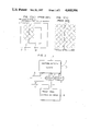
In such a method, however, improvement of the picture quality is not necessarily sufficient with respect to recording of halftone images through a halftone dot generator. Assuming that, for example, a halftone repeating pattern is partially formed by one main scanning in halftone processing by a halftone dot generator, it is anticipated that such a situation as shown in FIG. 1(a) may be frequently caused that a recording region 31 for first scanning is completed in the middle of the pattern at a boundary X and a subsequent recording region 32 for second scanning is started from the middle of the pattern at the boundary X. If the second sub scanning is started from a position corresponding to the boundary X in this case, it is indefinite from which part of the halftone pattern the halftone dot generator genrates halftone dots (i.e., it is uncertain whether or not the halftone dot generator generates the halftone dots continuously to those in the first scanning), and hence the halftone pattern is made discontinuous along the boundary X as shown in FIG. 1(b) in most of the case. In broad perspective, discontinuous portions of haltone thus formed are visible as black creases when area mean density is increased in the vicinity of boundaries while the same are visible as white creases when the area mean density is reduced. In order to avoid such a problem, the second sub scanning may be started again from the scanning origin to form a haltone pattern which is similar to (overlapping with) the first pattern absolutely from the beginning, whereas, in this case, useless scanning is performed without recording until it reaches an actually necessary scanning point (i.e., a sub scanning position corresponding to the boundary X ) for a relatively long time, and hence the processing time is increased.
SUMMARY OF THE INVENTION
The present invention is directed to a method of and an apparatus for generating halftone dots along predetermined halftone patterns on the recording plane or screen on the basis of input image signals in an image scanning/recording device. According to the present invention, scanning positions in recording and partial positions of the halftone patterns are previously related with each other, and in order to generate the halftone dots from the middle of the recording screen, a partial position of the halftone pattern corresponding to the scanning start position in the middle of the screen is preset to generate the halftone dots in compliance with the said relation from the preset partial position.
In a preferred embodiment of the present invention, the said relation is attained by previously relating the absolute sub scanning position obtained by counting the main scanning position and the number of sub scanning lines by counters with halftone dot density of the partial position of the halftone apttern. The halftone patterns may be cyclic, and in this case, the counters may be provided for the pattern cycles.
In another preferred embodiment of the present invention, the said presetting is performed, in case of starting record-scanning from an Ln -th scanning line from the scanning origin, by presetting the remainder of Ln /Lc assuming that Lc represents the number of pattern repeating cycle lines, or by presetting the remainder of (Ln -Lr)/Lc assuming that Lr represents the number of lines required for the rise of a scanning mechanism.
Accordingly, an object of the present invention is to provide a method of and an apparatus for generating halftone dots which can continuously connect halftone dots in connection boundaries without useless scanning, thereby to continuously connect specific patterns such as halftone patterns by a plurality of times of scanning in an image scanning/recording device.
These and other objects, features, aspects and advantages of the present invention will become more apparent from the following detailed description of the present invention when taken in conjunction with the accompanying drawings.
BRIEF DESCRIPTION OF THE DRAWINGS
FIG. 1 is an explanatory diagram showing connection between halftone patterns;
FIG. 2 is a block diagram showing an embodiment of a method of generating halftone dots according to the present invention; and
FIG. 3 is a block diagram showing an example of a drum-type scanner to which the present invention is applied.
DETAILED DESCRIPTION OF THE PREFERRED EMBODIMENTS
FIG. 2 is a block diagram showing an embodiment of a method of generating halftone dots according to the present invention. Scanning positions in recording and partial positions of halftone patterns are related with each other through a sub scanning line counter 1 and a main scanning position counter 2. The sub scanning line counter 1 receives a count signal 3 every time a recording head (not shown) completes scanning for one scanning line to count the same while the main scanning counter 2 receives count signals 4 which are supplied at appropriate intervals in correspondence to movement of the recording head performing scanning on a scanning line. In other words, count values of the sub scanning line counter 1 and the main scanning position counter 2 are respectively indicative of vertical and main scanning positions of the recording head, whereby the absolute record-scanning positions can be recognized by checking the contents of the said counters 1 and 2.
The absolute record-scanning positions are related with partial positons of halftone patterns through halftone pattern memory 5. The halftone pattern memory 5 is formed by, e.g., a look-up table, the contents of which are selected by the count values of the sub scanning line counter 1 and the main scanning position counter 2 and image input signals 6 from an input-scanning portion (not shown). The look-up table is previously provided to obtain binary image output signals 7 for resulting halftone dots in response to comparison of halftone dot density of the halftone pattern partial positons previously made to correspond to the absolute record-scanning positions which are determined by the count values of the sub scanning line counter 1 and the main scanning position counter 2 with density of the image input signal 6 at that time. The halftone pattern memory 5 may not be provided as a look-up table, but may form a calculating circuit. Also in this case, input/output relation is such that the image output signals 7 are determined by the count values of the sub scanning line counter 1 and the main scanning position counter 2 and the input image signals 6, similarly to the above description.
In general, halftone patterns are formed by repeating the same patterns (including the case of repeating a plurality of halftone patterns) as shown in FIG. 1, and hence the sub scanning line counter 1 and the main scanning position counter 2 may be set in count width matching with repeating cycles of the halftone patterns. This is because the count width can express all of partial positions in one pattern and halftone dot density corresponding to each partial position in the patterns is repeated commonly to all of the patterns, whereby counting may be repeated in the aforementioned cycles in response to changes in the record-scanning positions. Vertical and horizontal repeating cycles of the halftone patterns vary with yellow, magenta, cyan and black plates.
A present value calculating circuit 8 is adapted to calculate the count value of the sub scanning line counter 1, which count value corresponds to a scanning start point in case of starting record-scanning from the middle of the recording screen, in advance to starting of the scanning thereby to preset the said value in the sub scanning line counter 1. For example, consider such case where the sub scanning line counter 1 is reset at zero in the scanning origin while the counter 1 is upcounted with time, to start record-scanning from an Ln- th scanning line from the scanning origin. Assuming that symbol Lc represents the pattern repeating cycle line number (equivalent to the count width of the sub scanning line counter 1), the preset value calculating circuit 8 performs, before starting the scanning, the following calculation:
remainder of L.sub.n /L.sub.c                              . . . (1)
thereby to preset the value in the sub scanning line counter 1. The result of calculation of the expression (1) represents a partial position of the pattern which is to be univocally determined in correspondence to the scanning start point on the recording screen, so that halftone dots are generated from the said partial position of the pattern whereby the halftone dots can be obtained in continuation with those generated in advance to the Ln -th scanning line by previous scanning.
The main scanning position counter 2 is reset for every main scanning start point (start point of each scanning line) similarly to the conventional case, and no particular count value is preset at a start point of a region requiring main scanning. This is because it is practically impossible to start main scanning from the middle in the case of the drum-type scanner and because idling time is extremely short in the main scanning direction to cause no particular problem and hence there is no need to particularly start main scanning from the middle. Thus, as shown in FIG. 1(a), the main scanning position counter 2 starts upcounting from a main scanning start point of a recording region 31 to generate the halftone pattern in response to the count value thereof for a recording region 32 in second scanning, while the halftone pattern image only in the recording region 32 can be recorded by masking means (not shown) for generating masking signals in the second scanning.
When the scanning is performed through mechanical structure, slight rise time is required from starting of the scanning to transition to a stationarty scanning state. Therefore, it is necessary to start the scanning from a position slightly ahead of the actual scanning region, and in such case, the preset value in the expression (1) must be corrected in compliance with the number Lr of lines required for the said rise. Namely, in place of the expression (1), the preset value calculating circuit 8 calculates the following expression:
remainder of (L.sub.n -L.sub.r)/L.sub.c                    . . . (2)
thereby to preset the result of the calculation in the sub scanning line counter 1. The aforementioned masking means is operated also in the sub scanning direction, in addition to the main scanning direction.
The above description is made on the premise that the recording head (not shown) traces absolutely the same scanning locus in any case of a plurality of times of scanning. In order to attain this, for example, the scanning method as disclosed in the Japanese Patent Laying-Open Gazette No. 31359/1985 may be employed, which scanning method is hereinafter briefly described.
FIG. 3 is a block diagram showing an example of structure of components only in a recording area, in case of applying the embodiment as shown in FIG. 2 to a drum-type scanner. Referring to FIG. 3, a block 100 in dotted lines denotes the above-described halftone dot generating device as shown in FIG. 2, and detailed description thereof is omitted.
A recording drum 9 is driven by a main scanning motor 10 to be rotated, which rotation is encoded by a rotary encoder 11 to be outputted as a main scanning origin pulse A and a prescribed number of count pulses B per rotation. A recording head 12 is moved in the sub scanning direction through a feed screw 14, the rotation of which is driven by a sub scanning motor 13, and the amounts of movement thereof are encoded by a sub scanning encoder 15 from the number of rotation and the screw pitches of the feed screw 14 to be outputted as count pulses C corresponding to the amounts of movement. A linear encoder may be employed as the sub scanning encoder 15 to derive signals directly corresponding to the positions of the recording head 12 in place of the said count pulses C. An origin position sensor 16 detects the movement of the recording head 12 to the sub scanning origin, to output sub scanning origin pulses D.
Through the aforementioned pulse signals A to D, a control circuit 17 controls the recording head 12 to continuously trace the same scanning locus in a plurality of times of scanning. Description is now briefly made on such a control method, which is disclosed in the aforementioned Japanese Patent Laying-Open Gazette No. 31359/1985. First, a theoretical sub scanning position Ps is determined through the following expression:
P.sub.s =K(L.sub.n +θ/θ.sub.m)+K.sub.0         . . . (3)
where K represents a sub scanning feed pitch (=constant), KO represents distance (=constant) between the scanning start position in the sub scanning direction and the beginning end of the recording head 12 and θm represents the amount of entire main scanning position angle (constant value corresponding to 360°). Further, Ln represents the number of scanning lines, which can be recognized by counting the main scanning origin pulse A per rotation and θ represents a main scanning position angle which can be recognized by counting the count pulses B. On the other hand, an actual sub scanning position Ps ' is obtained by counting the count pulses C from the sub scanning encoder 15. This count value is reset by the sub scanning origin pulses D. On the basis of Ps and Ps ' thus obtained, the control circuit 17 controls the rotation of the sub scanning motor 13 to increase the feeding speed of the recording head 12 when Ps >Ps ' while reducing the said feeding speed when Ps <Ps ' , thereby to achieve the aforementioned control. Such control is performed only in an interval from supply of a scanning start pulse E to supply of a scanning end pulse F, i.e., a scanning interval. The scanning start pulse E obtained by the expression (1) is different from that obtained by the expression (2).
On the other hand, the main scanning origin pulse A and the count pulses B from the rotary encoder 11 are supplied through a gate circuit 18 to the sub scanning line counter 1 and the main scanning position counter 2. The gate circuit 18 is controlled by Q outputs of a flip-flop circuit 19, which in turn is set by the scanning start pulses E to generate high-level Q outputs and reset by the scanning end pulses F to output low-level Q outputs. Therefore, the gate circuit 18 is opened only in the sub scanning intervals, and the main scanning origin pulse A and the count pulses B from the rotary encoder 11 pass through the gate circuit 18 only in the sub scanning intervals, to be supplied to the sub scanning line counter 1 and the main scanning position counter 2.
As hereinabove described, the vertical line counter 1 is in count width indentical to the pattern repeating cycle of the halftone dot pattern, and is reset by the sub scanning origin pulses D from the origin position sensor 16 to count the main scanning origin pulse A. The main scanning origin pulse A corresponds to the count signal 3 (that supplied every time the recording head 12 completes scanning for one scanning line) as hereinabove described with reference to FIG. 2.
Similarly to the sub scanning line counter 1, the main scanning position counter 2 is in the count width identical to the pattern repeating cylce, and reset by the main scanning origin pulse A per rotation of the recording drum 9, to count the count pulses B which are generated in an appropriate number during the rotation. The count pulses B correspond to the count signals 4 (those generated at appropriate intervals in response to the movement of the recording head 12 performing scanning on one scanning line) as hereinabove described with reference to FIG. 2.
When sub scanning is started from a position other than the sub scanning origin, the preset value calculating circuit 8 performs calculation of the expression (1) or (2) as hereinabove described, to preset the value as obtained in the sub scanning line counter 1. The preset value calculating circuit 8 may be formed by a microcomputer or in random logic.
On the basis of the count values of the sub scanning line counter 1 and the main scanning position counter 2 and the image input signals 6, the halftone pattern memory 5 supplies binary image output signals 7 as resulting halftone dots by the operation as hereinabove described with reference to FIG. 1. The halftone dots thus generated are continuous to those generated in advance thereto even if the scanning is started from the middle of the recording screen, as hereinabove described.
A masking circuit 20 performs masking operation to pass the image output signals 7 thus obtained for regions required in the main and sub scanning directions, i.e., to cut image signals unnecessary for recording. The image output signals 7 passed through the masking circuit 20 are converted into optical signals by a light modulator 21, to be outputted from the recording head 12. Thus, the halftone dots are recorded on photosensitive material (not shown) on the recording drum 9.
In general, four halftone pattern memories 5 and four sub scanning line counters 1 are prepared in correspondence to four color printing plates (yellow, magenta, cyan and black plates). As to the preset value calculating circuit 8, four such circuits may be prepared or one preset value calculating circuit may be adapted to calculate four preset values in advance to starting scanning. Although the halftone pattern has been described as formed by one optical beam, record-scanning operation can be performed by multi-beam in order to reduce the scanning time. In this case, contents of the halftone pattern memory 5 may be formed to be divided into halftone patterns for respective optical beams, which are required by respective ones of the multiple beams. With respect to this, refer to, e.g., Japanese Patent Laying-Open Gazette No. 80639/1983.
According to the present invention as hereinabove described, the halftone patterns are always univocally determined with respect to the absolute record-scanning positions, whereby continuous halftone dots can be obtained even if scanning is performed only in a necessary scanning region in the middle of the recordig screen to connect images by a plurality of times of scanning, and hence plain layout processing time can be reduced.
Although the present invention has been described and illustrated in detail, it is clearly understood that the same is by way of illustration and example only and is not to be taken by way of limitation, the spirit and scope of the present invention being limited only by the terms of the appended claims.

Claims (9)

What is claimed is:
1. A method of generating halftone dots along predetermined halftone patterns on the recording screen on the basis of input image signals for use in an image scanning/recording unit, said method comprising the steps of:
previously relating scanning positions in recording with partial positions of halftone patterns;
presetting, in case of generating halftone dots from the middle of the screen, a partial position of a halftone pattern corresponding to a scanning start position in the middle of the recording screen; and
generating said halftone dots from said preset partial position in response to said relation.
2. A method of generating halftone dots in accordance with claim 1, wherein
said relating includes relating of the absolute sub scanning position obtained by counting a main scanning position and the number of sub scanning lines by counters with halftone dot density in said halftone pattern partial positions.
3. A method of generating halftone dots in accordance with claim 2, wherein
said halftone patterns are cyclic and said counters are provided for the pattern cycles.
4. A method of generating halftone dots in accordance with claim 1, wherein
said presetting includes presetting of the remainder of Ln /Lc assuming that Lc represents the pattern repeating cycle line number in case of starting record-scanning from an Ln -th scanning line from the scanning origin.
5. A method of generating halftone dots in accordane with claim 1, wherein
said presetting includes presetting of the remainder of (Ln -Lr)/Lc assuming that Lc represents the pattern repeating cycle line number and Lr represents the number of lines required for the rise of a scanning mechanism in case of starting record-scanning from an Ln -th scanning line from the scanning origin.
6. An apparatus for generating halftone dots along predetermined halftone patterns on the recording screen on the basis of input image signals for use in an image scanning/recording unit, said apparatus comprising:
counters for relating scanning positions in recording with partial positions of halftone patterns;
preset means for presetting an arbitrary partial position of a halftone pattern in the middle of the recording screen in said counters; and
halftone dot generating means for generating halftone dots in response to said counters from said preset partial position in case of generating halftone dots from the middle of the recording screen.
7. An apparatus for generating halftone dots in accordance with claim 6, wherein
said halftone patterns are cyclic and said counters are provided for pattern repeating cycles.
8. An apparatus for generating halftone dots in accordance with claim 7, wherein
said preset means includes means for presetting the remainder of Ln /Lc assuming that Lc represents the pattern repeating cycle line number in case of starting record-scanning from an Ln -th scanning line from the scanning origin.
9. An apparatus for generating halftone dots in accordance with claim 7, wherein
said preset means includes means for presetting the remainder of (Ln -Lr)/Lc assuming that Lc represents the pattern repeating cycle line number and Lr represets the number of lines required for the rise of a scanning mechanusm in case of starting record-scanning from an Ln -th scanning line from the scanning origin.
US06/860,492 1985-05-15 1986-05-07 Method and apparatus for generating halftone dots Expired - Fee Related US4668996A (en)

Applications Claiming Priority (2)

Application Number Priority Date Filing Date Title
JP60104329A JPS61261968A (en) 1985-05-15 1985-05-15 Method and device for generating dot
JP60-104329 1985-05-15

Publications (1)

Publication Number Publication Date
US4668996A true US4668996A (en) 1987-05-26

Family

ID=14377893

Family Applications (1)

Application Number Title Priority Date Filing Date
US06/860,492 Expired - Fee Related US4668996A (en) 1985-05-15 1986-05-07 Method and apparatus for generating halftone dots

Country Status (4)

Country Link
US (1) US4668996A (en)
EP (1) EP0201918B1 (en)
JP (1) JPS61261968A (en)
DE (1) DE3687083T2 (en)

Cited By (4)

* Cited by examiner, † Cited by third party
Publication number Priority date Publication date Assignee Title
US4833546A (en) * 1987-03-11 1989-05-23 Yamatoya & Co., Ltd. Photomechanical apparatus
US5144688A (en) * 1990-03-23 1992-09-01 Board Of Regents, The University Of Texas System Method and apparatus for visual pattern image coding
EP1005221A2 (en) * 1998-11-27 2000-05-31 Seiko Epson Corporation Image processing apparatus, method for processing images, and printing apparatus to which image processing method is applied
US20020140657A1 (en) * 2001-03-29 2002-10-03 Fuji Photo Film Co., Ltd. Halftone dot image display unit, and halftone dot image display program storage medium

Families Citing this family (2)

* Cited by examiner, † Cited by third party
Publication number Priority date Publication date Assignee Title
DE3850594T2 (en) * 1987-04-02 1995-02-23 Canon Kk Image recorder.
US4794241A (en) * 1988-01-21 1988-12-27 National Computer Systems Scannable document velocity detector

Citations (1)

* Cited by examiner, † Cited by third party
Publication number Priority date Publication date Assignee Title
US4327380A (en) * 1979-08-24 1982-04-27 Dainippon Screen Seizo Kabushiki Kaisha Control method for reproduction picture positions in a direction of a cylinder's axis

Family Cites Families (4)

* Cited by examiner, † Cited by third party
Publication number Priority date Publication date Assignee Title
US4254439A (en) * 1979-12-26 1981-03-03 International Business Machines Corporation Facsimile mid-page restart
JPS5964846A (en) * 1982-10-05 1984-04-12 Dainippon Screen Mfg Co Ltd Method for simultaneous recording of pattern and line drawing
JPS59189781A (en) * 1983-04-12 1984-10-27 Canon Inc Picture processing device
JPS6031359A (en) * 1983-07-29 1985-02-18 Dainippon Screen Mfg Co Ltd Scanning method and apparatus in picture scanning recorder

Patent Citations (1)

* Cited by examiner, † Cited by third party
Publication number Priority date Publication date Assignee Title
US4327380A (en) * 1979-08-24 1982-04-27 Dainippon Screen Seizo Kabushiki Kaisha Control method for reproduction picture positions in a direction of a cylinder's axis

Cited By (7)

* Cited by examiner, † Cited by third party
Publication number Priority date Publication date Assignee Title
US4833546A (en) * 1987-03-11 1989-05-23 Yamatoya & Co., Ltd. Photomechanical apparatus
US5144688A (en) * 1990-03-23 1992-09-01 Board Of Regents, The University Of Texas System Method and apparatus for visual pattern image coding
EP1005221A2 (en) * 1998-11-27 2000-05-31 Seiko Epson Corporation Image processing apparatus, method for processing images, and printing apparatus to which image processing method is applied
EP1005221A3 (en) * 1998-11-27 2002-04-17 Seiko Epson Corporation Image processing apparatus, method for processing images, and printing apparatus to which image processing method is applied
US7050194B1 (en) 1998-11-27 2006-05-23 Seiko Epson Corporation Image processing apparatus, method of processing images, and printing apparatus to which image processing method is applied
US20020140657A1 (en) * 2001-03-29 2002-10-03 Fuji Photo Film Co., Ltd. Halftone dot image display unit, and halftone dot image display program storage medium
US6753877B2 (en) * 2001-03-29 2004-06-22 Fuji Photo Film Co., Ltd. Halftone dot image display unit, and halftone dot image display program storage medium

Also Published As

Publication number Publication date
EP0201918A2 (en) 1986-11-20
DE3687083T2 (en) 1993-06-03
DE3687083D1 (en) 1992-12-17
JPS61261968A (en) 1986-11-20
EP0201918A3 (en) 1989-02-22
EP0201918B1 (en) 1992-11-11

Similar Documents

Publication Publication Date Title
US4499489A (en) Production of screen printing blocks
US5278582A (en) Printer driving circuit
US4916530A (en) High resolution halftone dot generator system including LED array
US4962981A (en) Optical scanner
US5430472A (en) Method and apparatus for eliminating distortion via overscanned illumination for optical printers and the like having high gamma photosensitive recording media and high addressability
JPH0335867B2 (en)
CA1281764C (en) Thermal printer with printing plate making mode
US4893195A (en) Image processing apparatus capable of eliminating moire pattern
US4668996A (en) Method and apparatus for generating halftone dots
US4652914A (en) Method of recording register marks
US5200761A (en) Thermal printing apparatus
EP0608474B1 (en) Pixel resolution enhancement employing encoded dot size control
US5262937A (en) Technique for precise color-to-color registration in thermal printers
GB1588743A (en) Methods of obtaining digital reproduction data for screening colour separations
US5838359A (en) Interpolated reference for improved digital feedback control regulation
US6809750B2 (en) Image forming apparatus and image forming method
JP2869321B2 (en) Polygon mirror jitter correction device
US5530555A (en) Method and apparatus for recording halftone dot image with different repeating units
JPS63128956A (en) Method of adjusting printing head
JP3513400B2 (en) Serial recording device and serial recording method
JPH03214864A (en) Color picture processor
JPH04189153A (en) Image forming device
JPH0612437B2 (en) Register mark recording method in image scanning recording apparatus
JPS638744A (en) Generating method for negative for endless plate
JPH02140054A (en) Picture processor

Legal Events

Date Code Title Description
AS Assignment

Owner name: DAINIPPON SCREEN MFG. CO., LTD., JAPAN

Free format text: ASSIGNMENT OF ASSIGNORS INTEREST;ASSIGNORS:HATAYAMA, FUMIHIRO;HIROSAWA, MAKOTO;SIGNING DATES FROM 19860417 TO 19860418;REEL/FRAME:004552/0036

Owner name: DAINIPPON SCREEN MFG. CO., LTD., 1-1, TENJINKITAMA

Free format text: ASSIGNMENT OF ASSIGNORS INTEREST.;ASSIGNORS:HATAYAMA, FUMIHIRO;HIROSAWA, MAKOTO;REEL/FRAME:004552/0036;SIGNING DATES FROM 19860417 TO 19860418

FEPP Fee payment procedure

Free format text: PAYOR NUMBER ASSIGNED (ORIGINAL EVENT CODE: ASPN); ENTITY STATUS OF PATENT OWNER: LARGE ENTITY

FPAY Fee payment

Year of fee payment: 4

FPAY Fee payment

Year of fee payment: 8

FEPP Fee payment procedure

Free format text: PAYOR NUMBER ASSIGNED (ORIGINAL EVENT CODE: ASPN); ENTITY STATUS OF PATENT OWNER: LARGE ENTITY

Free format text: PAYER NUMBER DE-ASSIGNED (ORIGINAL EVENT CODE: RMPN); ENTITY STATUS OF PATENT OWNER: LARGE ENTITY

REMI Maintenance fee reminder mailed
LAPS Lapse for failure to pay maintenance fees
FP Lapsed due to failure to pay maintenance fee

Effective date: 19990526

STCH Information on status: patent discontinuation

Free format text: PATENT EXPIRED DUE TO NONPAYMENT OF MAINTENANCE FEES UNDER 37 CFR 1.362