US4665848A - Method and apparatus for automatically hemming garments - Google Patents
Method and apparatus for automatically hemming garments Download PDFInfo
- Publication number
- US4665848A US4665848A US06/579,696 US57969684A US4665848A US 4665848 A US4665848 A US 4665848A US 57969684 A US57969684 A US 57969684A US 4665848 A US4665848 A US 4665848A
- Authority
- US
- United States
- Prior art keywords
- garment
- hem
- drive mechanism
- sewing
- folder device
- Prior art date
- Legal status (The legal status is an assumption and is not a legal conclusion. Google has not performed a legal analysis and makes no representation as to the accuracy of the status listed.)
- Expired - Lifetime
Links
Images


Classifications
-
- D—TEXTILES; PAPER
- D05—SEWING; EMBROIDERING; TUFTING
- D05B—SEWING
- D05B33/00—Devices incorporated in sewing machines for supplying or removing the work
-
- D—TEXTILES; PAPER
- D05—SEWING; EMBROIDERING; TUFTING
- D05D—INDEXING SCHEME ASSOCIATED WITH SUBCLASSES D05B AND D05C, RELATING TO SEWING, EMBROIDERING AND TUFTING
- D05D2305/00—Operations on the work before or after sewing
- D05D2305/02—Folding
- D05D2305/04—Folding longitudinally to the sewing direction
Definitions
- This invention relates to an apparatus and method for automatically folding and stitching the hem in tubular-shaped garments.
- Tubular shaped garment parts are commonly finished with a hem in which the raw edge of the fabric is folded over either in a single fold or double fold and a circumferencial stitch is sewn through the fold to form the hem.
- the bottom hem may vary in diameter from the smaller straight leg style (in the range of 13-16" circumference) to the larger bell type style (23-28") or the intermediate size flared style (16-23").
- a commercially successful production machine for sewing hems should be capable of accommdating these various styles. Similarly, a successful machine should be easy to load by the operator. The machine should also be able to apply the necessary tension to the fabric so that proper stitching may be accomplished in a smooth even fashion.
- none of the devices discloses a means for selectively varying the size of the device on which the garment to be hemmed is mounted and tensioned in order that various sizes and shapes of garments may be automatically folded or hemmed with the same apparatus in much the same manner as is disclosed by the present invention.
- Such apparatus comprises an expandable roller and cam assembly which is used to mount and tension the tubular garment about the assembly and to load the garment onto a folding device where the garment is then rotated through a pre-determined distance to form a double hem fold from the single fold hem in the garment prior to the garment being sewn.
- the apparatus of our invention has the added advantage of being able to accommodate all different types, sizes and shapes of tubular garments and to form hems in the garment of various depths.
- Our apparatus makes loading of garments onto the machine for hemming much easier than all known prior art devices, and the apparatus results in an excellent quality of hemming by eliminating ropiness in the cuffs of these tubular-shaped garments.
- the apparatus is further provided with the means for matching up the starting and finishing stitches in the hem of the garment and provides a savings in the hemming operations of garments by eliminating the time required to train operators since the skill required to operate the apparatus is minimal.
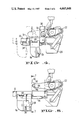
- FIG. 1 is a perspective view of the device as viewed from the operator station with the hem expanding assembly shown in solid line ready to receive a garment to be hemmed and shown in phantom line where the garment hem is tensioned and ready for sewing.
- FIGS. 2A, 2B and 2C are diagrammatic views of different diameter sizes of hems illustrating how the various expanding rollers are selected to accommodate different size garment legs and to create a minimum free span of fabric between control points.
- FIG. 3 is a front elevational view of the device of FIG. 1 illustrating the path of the garment hem in the loading position and also illustrating in phantom the maximum movement of the expanding roller assembly.
- FIG. 4 is a view similar to FIG. 3 illustrating the device when it is used on intermediate size hems.
- FIG. 5 is a view similar to FIGS. 3 and 4, illustrating the device when it is set up to accommodate the smaller size hems.
- FIG. 6 is an end elevational view of the device of FIG. 3 taken looking from the right hand thereof along line 6--6 and illustrating in phantom line the position of the garment edge in relation to the folder mechanism, sewing head and tensioning means.
- FIG. 7 is a sectional view taken along line 7--7 of FIG. 5 and illustrating the slide mechanism and the expanding roller assembly in its alternate position.
- FIG. 8 is a diagrammatic cross-sectional view of a single fold in the hem made by the operator as it is first positioned on the device.
- FIG. 9 is a diagrammatic cross-sectional view of the hem after it has been double folded and stitched by the device to form the desired hem.
- FIG. 10 is a top plan view of the device of FIG. 3 illustrating the path of the hem (shown in phantom line) and moving from right to left over the fixed guide, folding mechanism, presser foot and sewing needle, sewing machine feed rollers and associated indexing unit and over the expanding roller assembly.
- FIGS. 11 and 12 are diagrammatic cross-sectional views, similar to FIGS. 8 and 9, and illustrating, in FIG. 11, the single fold in the garmet when initially placed on the device, FIG. 12 illustrates the double fold made by the folding mechanism, the distance the fabric moves between the folder and the stitcher being shown by the arrow.
- FIGS. 13 and 14 are diagrammatic perspective views of the sewing machine feed rollers and indexing unit.
- FIG. 13 illustrates the drive train when the hem is initially made wherein the sewing machine drive is inoperative such that the fabric may move through the folder toward the needle without being stitched.
- FIG. 14 illustrates the drive train after the double folded fabric has arrived at the needle wherein the sewing machine drive is reactivated to make the stitch.
- an automatic hemming device 10 including a standard sewing machine 12 mounted on a pedestal 14 and including a platform 16 and drive motor 18 which may be vertically adjusted on a pedestal 14 to accommodate various operators.
- the operator would normally sit in front of the device and load the semifinished pants onto the device with the leg in a horizontal position and the leg bottom confronting and overlying mandrel 20.
- Each leg is hemmed independently of the other.
- the operator Before placing the leg on the device the operator also forms a first fold in the hem by tucking the raw edge into the leg for a distance of about 7/8" (this distance may vary depending on the desired end result).
- Device 10 has a folder or foldling mechanism for making the second fold or tuck in the leg of fabric. It must be understood that the distances and hem sizes specified herein are for illustration only and they may vary from application to application.
- Mandrel 20 (see FIG. 3) is formed of several fabric guiding parts including a fixed curvilinear guide 22 at the right hand side of FIG. 3 and a movable expanding roller assembly 24 spaced to the left from part 22.
- Assembly 24 is formed of three independent rollers, i.e., a large roller 26 at the left of FIG. 3 used for bell leg style hems, a medium roller 28 used for flared leg style hems and a small roller 30 for use on straight leg style hems.
- Assembly 24 includes carriage 31 mounted on ball slide 32 and movable thereon by piston cylinder 34 toward the phantom line position as viewed at the left of FIG. 3.
- Ball slide 32 is mounted on the front edge of platform 16.
- Cylinder 34 is air driven by a suitable control and pneumatic system (not shown) to move the roller assembly 24 away from fixed curvilinear guide 22 and to tension the leg bottom positioned there between.
- the means to move the rollers 26, 28 and 30 could very well be a radius arm or kinematic link providing approximate straight line motion in place of the linear slide disclosed.
- roller 26 and medium roller 28 are independently mounted on carriage 31 by hinged carriers 36 and 38, respectively, through pivot rod 40.
- Each carrier includes a latch 42a, 42b having a pin 44a, 44b locking the carrier in an upright position when placed in hole 48a and 48b of carriage 31 or swingable to a downward, out of the way position when pin 42a, 42b is in hole 50a, 50b. Either or both carriers may be swung out of the way as shown in FIGS. 4 and 5.
- Carriage 31 is pivoted so that at various times the rollers of the expandable roller assembly 24 may move down and out of the way depending on the circumference of the garment to be hemmed.
- Small roller 30 is rotably carried on upstanding strut 52 of carriage 31, while curvilinear guide 54 is carried near the lower end of strut 52. Both guide 22 and guide 54 extend outward into the plane of rollers 26, 28 and 30 and serve to support and guide the fabric around bobbin 56. Guide 22 also acts as the stationary part of mandrel 20 and directs the faric into folding mechanism 58, presser foot 60 and into the sewing machine feeder roll 62 and pinch roll 64 in stitching area 66. Guide 22 could also include a roller 67 as shown in FIG. 3.
- Folding mechanism 58 is a well known device and is movable by piston cylinder 68 to move end 70 against the preformed single fold and tuck the raw edge under for a second fold prior to stitching.
- Upstanding rail 71 on the throat plate guides the folded hem into the stitching area.
- Pinch roll 64 is vertically movable on slide rod 72 by a suitable piston (not shown) and allows the nip 63 between rolls 62 and 64 to open when the operator is loading the device (Part of Sewing Machine.)
- Feeder roll 62 is driven in synchronization with the sewing mechanism by sewing machine motor 18. The operator preselects the number of stitches depending on the diameter of the hem plus the overlapping staystitch. The total number of stitches is controlled by stitch counter 74. Prior to stitching, however, feeder roll 62 must initially move the untucked material through the folding mechanism and into the stitching area. This is accomplished by providing secondary drive means 76 in indexer 78 which will drive roller 62 an amount to move the double folded hem into the stitching area and then start the sewing machine motor which drives roller 62 through the sewing machine mechanism while the secondary drive means resets. Looking to FIGS. 13 and 14 there is shown in FIG. 13 roller 62 driven by secondary drive means 76 while sewing machine output shaft 80 is inoperative.
- Rack 82 rotates pinion 84 when cylinder 86 moves piston rod 88 outward.
- Pinion 84 drives the inner element 90 of one way or overriding clutch 92 through shaft 94 Wedge faces 96 on inner element 90 press clutch elements 98 outward into contact with ring gear 102.
- Rack 82, pinion 84, one way clutch 92, gear 104, and gear 106 form a drive train to rotate feed roller 62 through shaft 108.
- Shaft 110 on gear 104 also rotates gear 112 and ring gear 114 of one way clutch 116, but as shown, clutch elements 118 ride down wedge surfaces 120 and do not transmit power back through shaft 80 to the sewing machine mechanism.
- rack 82 trips sensor switch 122 and starts the sewing sequence.
- shaft 80 rotates gear 112 through now engaged clutch 116 and shaft 110 rotates gear 104 and gear 106 to continue to rotate feed roller 62.
- Piston rod 88 reverses direction, drawing rack 92 across pinion 84, but this motion is not transmitted back through one way clutch 92 because elements 98 are now on the inner side of wedge faces 96.
- other one way or overriding clutches could be used.
- the proper roller configuration is selected either for a large tube as shown in FIGS. 2A and 3; a medium tube as shown in FIGS. 2B and 4 or a small tube as shown in FIGS. 2C and 5.
- the proper stitch count is selected on terminal 128.
- the operator manually puts a first fold in the leg end and places the leg over the mandrel and actuates the sequence by pressing on a foot or hand switch not shown. Cylinder 132 expands outward from piston rod 134 to move carriage 31 away from fixed guide 22. This stroke varies depending on the diameter of the leg and the tension imparted thereto may be adjusted by regulating the air pressure in cylinder 132.
- Pinch roller 64 next moves downward to grip the material against feed roller 62.
- Folding mechanism 58 tucks the raw edge of the leg bottom into a second fold while the material is rotated around the mandrel by secondary drive means 76 in a counterclockwise direction as viewed in FIGS. 3-5.
- sensor switch 122 is tripped, indicating that the second folded material has arrived at the stitching area
- sewing machine motor 18 now advances the material through feed roll 62 while stitching the hem for the aforesaid designated number of stitches.
- Folder mechanism is retracted after the leg has made one revolution.
- pinch roller 64 is raised, carriage 31 is retracted to remove the tension on the garment and pusher 124 is actuated to dispense the finished leg from mandrel 20.
Landscapes
- Engineering & Computer Science (AREA)
- Textile Engineering (AREA)
- Sewing Machines And Sewing (AREA)
Abstract
Description
Claims (4)
Priority Applications (1)
| Application Number | Priority Date | Filing Date | Title |
|---|---|---|---|
| US06/579,696 US4665848A (en) | 1984-02-13 | 1984-02-13 | Method and apparatus for automatically hemming garments |
Applications Claiming Priority (1)
| Application Number | Priority Date | Filing Date | Title |
|---|---|---|---|
| US06/579,696 US4665848A (en) | 1984-02-13 | 1984-02-13 | Method and apparatus for automatically hemming garments |
Publications (1)
| Publication Number | Publication Date |
|---|---|
| US4665848A true US4665848A (en) | 1987-05-19 |
Family
ID=24317971
Family Applications (1)
| Application Number | Title | Priority Date | Filing Date |
|---|---|---|---|
| US06/579,696 Expired - Lifetime US4665848A (en) | 1984-02-13 | 1984-02-13 | Method and apparatus for automatically hemming garments |
Country Status (1)
| Country | Link |
|---|---|
| US (1) | US4665848A (en) |
Cited By (15)
| Publication number | Priority date | Publication date | Assignee | Title |
|---|---|---|---|---|
| US4730566A (en) * | 1984-09-18 | 1988-03-15 | Porter Sewing Machines, Inc. | Automatic pocket label stitcher |
| US5029541A (en) * | 1988-05-31 | 1991-07-09 | Union Special Gmbh | Device for the formation and sewing of a hem at an opening in a workpiece |
| US5031552A (en) * | 1990-05-10 | 1991-07-16 | The Charles Stark Draper Laboratory, Inc. | Drive assembly for seam-forming apparatus |
| EP0460468A1 (en) * | 1990-05-25 | 1991-12-11 | Texpa-Arbter Maschinenbaugesellschaft mbH | Apparatus for joining automatically the beginning and the end of a hem in a circular textile material |
| US5131336A (en) * | 1990-05-18 | 1992-07-21 | Pegasus Sewing Machine Mfg. Co., Ltd. | Waist part cloth guiding device for a sewing machine |
| US5354831A (en) * | 1992-07-17 | 1994-10-11 | Degussa Aktiengesellschaft | Shaped organopolysiloxanes containing sulfonate groups, a process for their production and their use |
| US5505149A (en) * | 1995-04-18 | 1996-04-09 | Jet Sew Technologies, Inc. | Method and apparatus for attaching sleeves to shirt bodies |
| US5570647A (en) * | 1994-09-23 | 1996-11-05 | Union Special Corporation | Automatic attachment of a rib knit band to a shirt body |
| US5806449A (en) * | 1996-04-03 | 1998-09-15 | Jet Sew Technologies, Inc. | Method and apparatus for attaching sleeves to shirt bodies |
| US5918560A (en) * | 1997-11-17 | 1999-07-06 | Atlanta Attachment Company | Textile fold control system with hem engager |
| US6024036A (en) * | 1997-11-17 | 2000-02-15 | Hams Corporation | Sewing machine for automatically hemming garments |
| US20110083596A1 (en) * | 2008-06-06 | 2011-04-14 | Hideo Asao | Sewing machine |
| CN109183290A (en) * | 2018-11-26 | 2019-01-11 | 湖州韩源进出口有限公司 | A kind of garment production processing bottom hemmer |
| CN109537179A (en) * | 2018-12-27 | 2019-03-29 | 深圳市圣召精密机械有限公司 | Exempt to turn over clothing sewing machine and exempts to turn over clothing sewing technology |
| CN110396773A (en) * | 2019-06-19 | 2019-11-01 | 张之鹏 | The sewing control method of sewing machine and the sewing control system of sewing machine |
Citations (8)
| Publication number | Priority date | Publication date | Assignee | Title |
|---|---|---|---|---|
| US4098204A (en) * | 1975-09-05 | 1978-07-04 | Yamato Mishin Seizo Kabushiki Kaisha | Apparatus for stretch-sewing a hem in tubular fabric |
| US4171575A (en) * | 1978-04-06 | 1979-10-23 | Levi Strauss & Co. | Actual sew length measuring device |
| EP0044648A2 (en) * | 1980-07-14 | 1982-01-27 | G.M. Pfaff Aktiengesellschaft | Control system for sewing machine |
| US4381719A (en) * | 1980-05-16 | 1983-05-03 | Durkoppwerke Gmbh | Sewing machine with a stitch counter and correction unit |
| US4455956A (en) * | 1980-09-18 | 1984-06-26 | Brother Kogyo Kabushiki Kaisha | Cyclic sewing machine |
| US4473017A (en) * | 1982-02-12 | 1984-09-25 | Amf Inc. | Apparatus for automatically hemming tubular garments on a sewing machine |
| US4479447A (en) * | 1981-06-26 | 1984-10-30 | Union Special Gmbh | Method and apparatus for sewing on a tubular workpiece edge |
| US4555999A (en) * | 1984-04-09 | 1985-12-03 | Conner William R | Waistband indexing method and apparatus |
-
1984
- 1984-02-13 US US06/579,696 patent/US4665848A/en not_active Expired - Lifetime
Patent Citations (8)
| Publication number | Priority date | Publication date | Assignee | Title |
|---|---|---|---|---|
| US4098204A (en) * | 1975-09-05 | 1978-07-04 | Yamato Mishin Seizo Kabushiki Kaisha | Apparatus for stretch-sewing a hem in tubular fabric |
| US4171575A (en) * | 1978-04-06 | 1979-10-23 | Levi Strauss & Co. | Actual sew length measuring device |
| US4381719A (en) * | 1980-05-16 | 1983-05-03 | Durkoppwerke Gmbh | Sewing machine with a stitch counter and correction unit |
| EP0044648A2 (en) * | 1980-07-14 | 1982-01-27 | G.M. Pfaff Aktiengesellschaft | Control system for sewing machine |
| US4455956A (en) * | 1980-09-18 | 1984-06-26 | Brother Kogyo Kabushiki Kaisha | Cyclic sewing machine |
| US4479447A (en) * | 1981-06-26 | 1984-10-30 | Union Special Gmbh | Method and apparatus for sewing on a tubular workpiece edge |
| US4473017A (en) * | 1982-02-12 | 1984-09-25 | Amf Inc. | Apparatus for automatically hemming tubular garments on a sewing machine |
| US4555999A (en) * | 1984-04-09 | 1985-12-03 | Conner William R | Waistband indexing method and apparatus |
Cited By (21)
| Publication number | Priority date | Publication date | Assignee | Title |
|---|---|---|---|---|
| US4730566A (en) * | 1984-09-18 | 1988-03-15 | Porter Sewing Machines, Inc. | Automatic pocket label stitcher |
| US5029541A (en) * | 1988-05-31 | 1991-07-09 | Union Special Gmbh | Device for the formation and sewing of a hem at an opening in a workpiece |
| US5031552A (en) * | 1990-05-10 | 1991-07-16 | The Charles Stark Draper Laboratory, Inc. | Drive assembly for seam-forming apparatus |
| WO1991017298A1 (en) * | 1990-05-10 | 1991-11-14 | The Charles Stark Draper Laboratory, Inc. | Drive assembly for seam-forming apparatus |
| US5131336A (en) * | 1990-05-18 | 1992-07-21 | Pegasus Sewing Machine Mfg. Co., Ltd. | Waist part cloth guiding device for a sewing machine |
| EP0460468A1 (en) * | 1990-05-25 | 1991-12-11 | Texpa-Arbter Maschinenbaugesellschaft mbH | Apparatus for joining automatically the beginning and the end of a hem in a circular textile material |
| US5271347A (en) * | 1990-05-25 | 1993-12-21 | Francisco Carreras Fontcuberta | Process and associated apparatus for joining automatically the beginning and the end of a hem in a circular textile material |
| US5354831A (en) * | 1992-07-17 | 1994-10-11 | Degussa Aktiengesellschaft | Shaped organopolysiloxanes containing sulfonate groups, a process for their production and their use |
| US5709162A (en) * | 1994-09-23 | 1998-01-20 | Union Special Corporation | Semi-automatic method to attach circular collars to T-shirts |
| US5570647A (en) * | 1994-09-23 | 1996-11-05 | Union Special Corporation | Automatic attachment of a rib knit band to a shirt body |
| US5505149A (en) * | 1995-04-18 | 1996-04-09 | Jet Sew Technologies, Inc. | Method and apparatus for attaching sleeves to shirt bodies |
| US5806449A (en) * | 1996-04-03 | 1998-09-15 | Jet Sew Technologies, Inc. | Method and apparatus for attaching sleeves to shirt bodies |
| US5918560A (en) * | 1997-11-17 | 1999-07-06 | Atlanta Attachment Company | Textile fold control system with hem engager |
| US6024036A (en) * | 1997-11-17 | 2000-02-15 | Hams Corporation | Sewing machine for automatically hemming garments |
| US20110083596A1 (en) * | 2008-06-06 | 2011-04-14 | Hideo Asao | Sewing machine |
| US8302548B2 (en) * | 2008-06-06 | 2012-11-06 | Midori Anzen Co., Ltd. | Sewing machine |
| CN109183290A (en) * | 2018-11-26 | 2019-01-11 | 湖州韩源进出口有限公司 | A kind of garment production processing bottom hemmer |
| CN109183290B (en) * | 2018-11-26 | 2024-06-07 | 天津鑫美华服装有限公司 | Lower hem flanging device for clothing production and processing |
| CN109537179A (en) * | 2018-12-27 | 2019-03-29 | 深圳市圣召精密机械有限公司 | Exempt to turn over clothing sewing machine and exempts to turn over clothing sewing technology |
| CN109537179B (en) * | 2018-12-27 | 2024-05-31 | 珠海市路得智能科技有限公司 | Automatic sewing equipment without turning over clothes |
| CN110396773A (en) * | 2019-06-19 | 2019-11-01 | 张之鹏 | The sewing control method of sewing machine and the sewing control system of sewing machine |
Similar Documents
| Publication | Publication Date | Title |
|---|---|---|
| US4665848A (en) | Method and apparatus for automatically hemming garments | |
| US3865058A (en) | Method and apparatus for forming and joining hems, particularly on tubular articles | |
| US5437238A (en) | Waist band attachment system | |
| US3898941A (en) | Apparatus for manufacturing and stacking hemmed fabric pieces | |
| US4098204A (en) | Apparatus for stretch-sewing a hem in tubular fabric | |
| US5709162A (en) | Semi-automatic method to attach circular collars to T-shirts | |
| US4114544A (en) | Apparatus for forming loops on a garment | |
| US4191117A (en) | Method and apparatus for attaching an elastic band to a tubular workpiece | |
| JPS58138480A (en) | Automatic hemming device for free end of cylindrical section of cloth | |
| US4484532A (en) | Apparatus for blind stitching an S-shaped hem | |
| US4947771A (en) | Sewing machine | |
| US3903818A (en) | Apparatus for the making of straight seams, for example false creases in trousers | |
| US3780679A (en) | Apparatus for producing endless bands | |
| US4901657A (en) | Multifunction sewing machine with tape feeding, cutting and hemming apparatus | |
| US4739718A (en) | Method and apparatus for sewing a waistband and applying it to a garment | |
| US3481292A (en) | Hemming device | |
| GB1566078A (en) | Button siwing machine | |
| US4558653A (en) | Label advancing system for a line closer machine | |
| EP0028095B1 (en) | Method and device of attaching a knitted fabric strip to a piece of fabric | |
| JPH05208084A (en) | Sewing method and device therefor | |
| US5622125A (en) | Automatic coverstitch on circular garment bands | |
| JPS6114837B2 (en) | ||
| US4223815A (en) | Post form stay inserter for shirt collars | |
| US2383654A (en) | Combined tie folding and slip stitch sewing machine | |
| JP2567087B2 (en) | Automatic stitching device |
Legal Events
| Date | Code | Title | Description |
|---|---|---|---|
| AS | Assignment |
Owner name: LEVI STRAUSS & CO. Free format text: ASSIGNMENT OF ASSIGNORS INTEREST.;ASSIGNORS:MICHAELS, SID;SILVA, PEDRO T.;REEL/FRAME:004294/0788 Effective date: 19831215 |
|
| STCF | Information on status: patent grant |
Free format text: PATENTED CASE |
|
| FEPP | Fee payment procedure |
Free format text: PAYOR NUMBER ASSIGNED (ORIGINAL EVENT CODE: ASPN); ENTITY STATUS OF PATENT OWNER: LARGE ENTITY |
|
| FPAY | Fee payment |
Year of fee payment: 4 |
|
| FEPP | Fee payment procedure |
Free format text: PAYER NUMBER DE-ASSIGNED (ORIGINAL EVENT CODE: RMPN); ENTITY STATUS OF PATENT OWNER: LARGE ENTITY |
|
| FPAY | Fee payment |
Year of fee payment: 8 |
|
| REMI | Maintenance fee reminder mailed | ||
| FPAY | Fee payment |
Year of fee payment: 12 |
|
| SULP | Surcharge for late payment | ||
| AS | Assignment |
Owner name: BANK OF AMERICA, N.A., AS COLLATERAL AGENT, CALIFO Free format text: SECURITY AGREEMENT;ASSIGNOR:LEVI STRAUSS & CO.;REEL/FRAME:010579/0206 Effective date: 20000120 |
|
| AS | Assignment |
Owner name: LEVI STRAUSS & CO., CALIFORNIA Free format text: RELEASE;ASSIGNOR:BANK OF AMERICA, N.A., AS ADMINISTRATIVE AGENT;REEL/FRAME:011497/0485 Effective date: 20010201 Owner name: BANK OF AMERICA, N.A., AS ADMINISTRATIVE AGENT, CA Free format text: SECURITY AGREEMENT;ASSIGNOR:LEVI STRAUSS & CO.;REEL/FRAME:011497/0494 Effective date: 20010201 |
|
| AS | Assignment |
Owner name: LEVI STRAUSS & CO., CALIFORNIA Free format text: RELEASE OF SECURITY AGREEMENT;ASSIGNOR:BANK OF AMERICA, N.A., AS ADMINISTRATIVE AGENT;REEL/FRAME:013699/0480 Effective date: 20030131 Owner name: CITICORP NORTH AMERICA, INC., AS ADMINISTRATIVE AG Free format text: SECURITY AGREEMENT;ASSIGNOR:LEVI STRAUSS & CO.;REEL/FRAME:013699/0490 Effective date: 20030131 |
|
| AS | Assignment |
Owner name: BANK OF AMERICA, N.A., AS AGENT, CALIFORNIA Free format text: SECURITY AGREEMENT;ASSIGNOR:LEVI STRAUSS & CO.;REEL/FRAME:014015/0001 Effective date: 20030929 |
|
| AS | Assignment |
Owner name: BANK OF AMERICA, AS ADMINISTRATIVE AGENT, CALIFORN Free format text: SECURITY AGREEMENT;ASSIGNOR:LEVI STRAUSS & CO.;REEL/FRAME:014015/0482 Effective date: 20030929 |
|
| AS | Assignment |
Owner name: LEVI STRAUSS & CO., CALIFORNIA Free format text: RELEASE OF SECURITY INTEREST;ASSIGNOR:CITICORP NORTH AMERICA, INC., AS ADMINISTRATIVE AGENT;REEL/FRAME:014083/0787 Effective date: 20030929 |
|
| AS | Assignment |
Owner name: LEVI STRAUSS & CO., CALIFORNIA Free format text: RELEASE BY SECURED PARTY;ASSIGNOR:BANK OF AMERICA, N.A.;REEL/FRAME:017325/0797 Effective date: 20060317 |