US4665286A - Motor starting and automatic reversing switch - Google Patents
Motor starting and automatic reversing switch Download PDFInfo
- Publication number
- US4665286A US4665286A US06/835,627 US83562786A US4665286A US 4665286 A US4665286 A US 4665286A US 83562786 A US83562786 A US 83562786A US 4665286 A US4665286 A US 4665286A
- Authority
- US
- United States
- Prior art keywords
- blades
- switch
- pair
- blade
- shaft
- Prior art date
- Legal status (The legal status is an assumption and is not a legal conclusion. Google has not performed a legal analysis and makes no representation as to the accuracy of the status listed.)
- Expired - Lifetime
Links
- 238000004804 winding Methods 0.000 claims abstract description 57
- 230000006698 induction Effects 0.000 claims abstract description 8
- 239000011810 insulating material Substances 0.000 claims abstract description 5
- 230000007935 neutral effect Effects 0.000 claims description 14
- 230000003247 decreasing effect Effects 0.000 claims description 6
- 239000000463 material Substances 0.000 description 3
- 239000011435 rock Substances 0.000 description 3
- 239000004020 conductor Substances 0.000 description 2
- 238000010586 diagram Methods 0.000 description 2
- ASMQPJTXPYCZBL-UHFFFAOYSA-N [O-2].[Cd+2].[Ag+] Chemical compound [O-2].[Cd+2].[Ag+] ASMQPJTXPYCZBL-UHFFFAOYSA-N 0.000 description 1
- 230000006978 adaptation Effects 0.000 description 1
- 239000000956 alloy Substances 0.000 description 1
- 229910045601 alloy Inorganic materials 0.000 description 1
- DMFGNRRURHSENX-UHFFFAOYSA-N beryllium copper Chemical compound [Be].[Cu] DMFGNRRURHSENX-UHFFFAOYSA-N 0.000 description 1
- 239000012634 fragment Substances 0.000 description 1
- 230000005484 gravity Effects 0.000 description 1
- 238000002955 isolation Methods 0.000 description 1
- 238000004519 manufacturing process Methods 0.000 description 1
- 229910052751 metal Inorganic materials 0.000 description 1
- 239000002184 metal Substances 0.000 description 1
- 230000001681 protective effect Effects 0.000 description 1
Images




Classifications
-
- H—ELECTRICITY
- H01—ELECTRIC ELEMENTS
- H01H—ELECTRIC SWITCHES; RELAYS; SELECTORS; EMERGENCY PROTECTIVE DEVICES
- H01H35/00—Switches operated by change of a physical condition
- H01H35/06—Switches operated by change of speed
- H01H35/10—Centrifugal switches
-
- H—ELECTRICITY
- H01—ELECTRIC ELEMENTS
- H01H—ELECTRIC SWITCHES; RELAYS; SELECTORS; EMERGENCY PROTECTIVE DEVICES
- H01H1/00—Contacts
- H01H1/12—Contacts characterised by the manner in which co-operating contacts engage
- H01H1/14—Contacts characterised by the manner in which co-operating contacts engage by abutting
- H01H1/24—Contacts characterised by the manner in which co-operating contacts engage by abutting with resilient mounting
- H01H1/26—Contacts characterised by the manner in which co-operating contacts engage by abutting with resilient mounting with spring blade support
- H01H1/28—Assembly of three or more contact-supporting spring blades
-
- H—ELECTRICITY
- H01—ELECTRIC ELEMENTS
- H01H—ELECTRIC SWITCHES; RELAYS; SELECTORS; EMERGENCY PROTECTIVE DEVICES
- H01H19/00—Switches operated by an operating part which is rotatable about a longitudinal axis thereof and which is acted upon directly by a solid body external to the switch, e.g. by a hand
- H01H19/54—Switches operated by an operating part which is rotatable about a longitudinal axis thereof and which is acted upon directly by a solid body external to the switch, e.g. by a hand the operating part having at least five or an unspecified number of operative positions
- H01H19/60—Angularly-movable actuating part carrying no contacts
- H01H19/62—Contacts actuated by radial cams
-
- H—ELECTRICITY
- H01—ELECTRIC ELEMENTS
- H01H—ELECTRIC SWITCHES; RELAYS; SELECTORS; EMERGENCY PROTECTIVE DEVICES
- H01H21/00—Switches operated by an operating part in the form of a pivotable member acted upon directly by a solid body, e.g. by a hand
- H01H21/54—Lever switches with blade-type contact co-operating with one or two spring-clip contacts, e.g. knife switch
- H01H21/60—Change-over switches with stable intermediate position
Definitions
- This invention relates to a switch for controlling the starting and automatic reversing of single phase induction motors such as might be used, for example, and not limitation, to drive a garbage disposer unit.
- Switches that start single phase induction motors and reverse the rotation of the motors if the rotor shaft drops below a predetermined speed due to an overload or comes to a stop are known in the prior art.
- Automatically reversing motors are especially desirable to drive garbage disposers in which a jam-up can often be cleared by simply reversing the rotational direction of the motor.
- Switches for starting and automatically reversing single phase induction motors are described in U.S. Pat. Nos. 2,673,272, 2,683,844, 2,701,855, 2,850,592 and 3,157,762 for example.
- Most currently available reversing switches are either electronic devices which are costly or some sort of friction activated devices which are known to be not as reliable as they ought to be.
- the present invention features a switch that can start and automatically reverse an induction motor that has one start winding; that can be changed from a reversing switch to a starting switch by simply eliminating some parts; that has parts which are common for reducing the number of different parts; that has parts which are designed to permit overtravel to thereby eliminate the need for accurate control of tolerances of the assembled parts and that enhances reliability by employment of the simple mechanical motion of a reversely tiltable switch operating lever in combination with a centrifugally controlled rotating actuator.
- the new switch cooperates with an actuator comprised of a disc that fits over the shaft of the motor to rotate with the shaft and shift axially of the shaft.
- a device is mounted on the shaft and responds to changes in centrifugal force due to the motor stopping or slowing to below a predetermined rotational speed to shift the actuator disc from one position to another to thereby operate the starting and reversing switch.
- the new switch is comprised of a generally planar base member composed of an insulating material. Laterally spaced apart pairs of deflectable flat spring contact blades are mounted to the base member. The blades in each pair are superimposed and mounted in cantilever fashion so that their free ends can be deflected.
- An insulating operator comprised of a shaft with an operating lever at one end and diametrically opposite and spaced apart radially extending arms on the shaft being disposed between the pairs of springy, deflectable blades operates the the starting and reversing switch.
- the lever on the operator shaft is arranged in alignment with the actuator disc whose axial position on the shaft is governed by a centrifugal device responsive to motor speed.
- the radially extending arms on the operator shaft then rotate and push a blade from one pair into contact with its cooperating stationary contact and a blade from the other pair into contact with its cooperating stationary contact to provide current flow in one direction through the contacts and the starting winding so as to cause the rotor of the motor to turn in one direction.
- the disc shifts again and wipes against the operator shaft lever to rock the shaft in the opposite direction.
- the arms on the shaft then force the opposite blades in each pair of blades to contact their cooperating stationary contacts.
- the starting and reversing switch is supplied from the power mains through a switch which, when closed, immediately connects the running winding of the motor across the power lines.
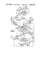
- FIG. 1 is a perspective view of the new starting and reversing switch assembly in conjunction with the rotating disc that actuates it;
- FIG. 2 is a vertical section taken on a line corresponding to 2-2 in FIG. 1;
- FIG. 3 is a vertical section taken on a line corresponding to 3-3 in FIG. 1, showing the starting circuits switch blades in non-conductive condition as would be in the case when the motor shaft is up to operating speed so the starting winding of the motor would be deenergized;
- FIG. 4 is a section structurally similar to FIG. 3 but showing the operator shaft lever angulated in one direction to close one set of contacts and establish current flow in one direction in the starting winding of the motor;
- FIG. 5 is a vertical section taken on a line corresponding 5-5 in FIG. 1;
- FIG. 6 is a perspective exploded view of the switch depicted in FIG. 1;
- FIG. 7 shows part of the motor and rotor shaft on which there is a centrifugal device for actuating the disc that operates the control lever of the starting and reversing switch in a situation where the motor speed has decreased so the actuating disc is about to tilt the operating shaft lever to bring about a switching function;
- FIG. 8 is comparable to the preceding figure except that the centrifugal device is shown in a state in which it would te when the motor shaft is up to operating speed in one direction of rotation;
- FIGS. 9-11 are diagrams for explaining the various operating sequences of the starting and reversing switch.
- FIG. 12 is similar to FIG. 6 except that in FIG. 12 the switch is adapted for controlling a non-reversing motor such that certain parts of the switch shown in the earlier embodiment can simply be omitted to make the adaptation.
- the new switch comprises a base member 10 composed of a rigid insulating plastic material.
- the electrical conducting elements and support members arranged on the top surface of base member 10 are mirror images of those on the bottom surface. All of the elements shown in FIGS. 1 and 6 are used when the switch is used for controlling the starting winding of the motor and for reversing the motor but one of the sets of elements on the top or the bottom of the base member can be removed if it is desired to simply use the switch for starting a single phase motor that is to run in the same direction each time it is energized.
- Spade connector 11 has one of the power lines L1 connected to it. There is a manually operated single pole main switch 24 in the power line. Spade connector 11 is part of a stiff flat metal conducting support plate 12. Spade connector 13 is also connected to the power line and is part of a stiff conducting support plate 14. As can be seen in FIG. 6, spade connectors 11 and 13 are at the top and bottom of base member 10 and are electrically connected by means of an eyelet 15 which is flared or staked at both ends. Rivets could be used in place of eyelets. Spade connector 17 is part of a support plate 18 which resides at the top of base member 10. As shown diagrammatically in FIG. 6, spade connector 17 connects to a conductor 19 leading to one end of the motor starting winding 20.
- the second side of the power mains, L2 connects to either of spade connectors 25 on plate 26 or connector 27 on plate 28.
- the motor running winding 21 is connected permanently between connector 14 which connects to line L1 and connector 26 which connects to line L2.
- the eyelet 29 which mounts plates 26 and 28 to base 10 also connects plates 26 and 28 electrically.
- Switch blades 36 and 37 fasten to the top and bottom, respectively, of base member 10 where they become connected in common to single rigid support plates 12 and 14 by means of eyelet 15. Blades 36 and 37 in one pair are thus mounted in cantilever fashion and are superimposed but spaced apart from each other by at least the thickness of the base member in the region where they are fastened. Blades 36 and 37 are springy and deflectable and typically composed of beryllium copper. Near the free end of each of the blades 36 and 37, there is an electric contact element 38 and 39 which are desirably composed of silver cadmium oxide alloy. A corresponding pair of cantilever supported switch blades 40 and 41 are mounted to the top and bottom of base member 10 laterally spaced from and in parallel with blades 36 and 37.
- Blades 40 and 41 are similarly spaced apart by at least the thickness of base member 10 where they are mounted. They are electrically interconnected with connector plates 26 and 28 by means of eyelet 29. These blades are provided with contact elements 43 and 44 at their free ends. They are composed of the same material and have the same properties as blades 36 and 37.
- Double blade member 45 is a double bladed member made of the same material as blade 36, for instance.
- Double blade member 45 has a flat central region 46 on which it is mounted and two unitary oppositely extending flexible blade members 47 and 48. As can be seen in FIG. 6, double blade member 45 is mounted to base member 10 on its upstanding bosses 49 and 50 by means of eyelets 51 and 52. The remote ends of deflectable blades 47 and 48 of double blade member 45 are provided with contact elements 53 and 54.
- contact 53 of double blade element 45 is arranged over contact 38 of single blade 36 and there is a space between single blade 36 and blade 47 so their contacts 38 and 53 are not normally in contact.
- the other blade portion 48 of double blade member 45 is arranged over and in spaced relationship with single blade 40 so the contact element 54 on double blade element 48 and contact element 43 on the single blade 40 are aligned with each other and spaced apart.
- single blade 36 can be pushed upwardly for its contact element 38 to make a resilient contact with contact element 53 on blade 47 on the double blade member 45.
- blade 40 which is laterally spaced and oppositely directed from blade 36 can be deflected upwardly for its contact element 43 to make a resilient contact with contact element 54 on blade 48 of the double blade member 45.
- base member 10 The arrangement of the parts at the bottom of base member 10 is similar to the arrangement on top which was just described.
- another double blade member 60 having individual deflectable blades 61 and 62 on which there are contact elements 63 and 64.
- single blade element 41 is superimposed over blade 61 on double blade member 60 and contact elements 44 and 63 are in alignment.
- single blade element 37 is superimposed over blade 62 of the double blade member 60 and contact elements 39 and 64 are in alignment but spaced apart.
- blade 37 can be deflected for its contact element 39 to make resilient contact with contact element 64 on blade 62 of double blade member 60.
- single blade 41 can be deflected for its contact element 44 to make resilient contact with contact element 63 on blade 61 of double blade member 60.
- Double blade member 60 is secured to bosses on the bottom of base member 10 under the compressive force of stiff member 30 which is held by two eyelets 65 and 66 to base member 10.
- Most of the flexible blades and rigid supports, single blade 40 and stiff support 28 for example, have notches such as the one marked 69 for engaging with bosses such as the one marked 70 to keep the parts in alignment.
- Switch operator 75 is composed of a rigid plastic insulating material and comprises a shaft 76, oppositely radially extending arms 77 and 78 and an operating lever 79.
- Shaft 76 of the switch operator is set in recesses 80 and 81 in base member 10 for rotating through a limited angle.
- radially extending arm 78 is disposed between the top single switch blade 36 and the bottom single switch blade 37 which is easier to see in FIG. 3.
- FIG. 3 In FIG.
- FIG. 5 shows how the other radially extending arm 77 of the switch operator is disposed between top single blade 40 and bottom single blade 41.
- radially extending arm 77 in FIG. 5 will deflect blade 41 and put the contact element 44 on single blade 41 into contact with contact element 63 on one blade 61 of double blade member 60.
- switch operator 79 is swung clockwise, upper single blade 40 will be deflected such that its contact element 43 will come into contact with contact element 54 on double blade member 45.
- the switch base member 10 is fastened by means of machine screws 81 to mounting posts 82 and 83 which, in this particular design, are formed integrally with the end cap 84 of an electric motor 85.
- the motor shaft is marked 86 and is rotatable in a bushing 87.
- a fragment of the rotor 88 and the stator 89 are depicted in FIG. 7. Sections through one of the starting winding coils 20 and running winding coils 21 are shown.
- the starting and reversing switch actuator shown in FIG. 7 is a basically conventional centrifugal force operated type which is generally designated by the reference numeral 90. It comprises a sleeve 91 which has an integral flange or disc 92 extending radially from it. The bottom of the disc is smooth. In FIG. 7, disc 92 is presently in its lowest obtainable position in which case it is holding switch operating lever 79 in a position that is angulated from vertical in a direction that depends on which direction the motor was turning when it last came to a stop.
- Centrifugal actuator 90 includes a body 93 that is shaped somewhat like a truncated pyramid which has an integral sleeve 94 which fits tightly on motor shaft 86.
- switch operating lever 79 will tilt clockwise as viewed from the right side in FIG. 7.
- the switch blades are repositioned so that the direction of current flow through the starting winding 20 of the motor will reverse and the motor rotation will reverse concurrently. If the motor comes to a complete stop as a result of the mains switch 24 being opened, the starting and reversing switch blades will be set in such a position that the next time the motor is energized, it will rotate in a direction opposite from that which it rotated before it was deenergized.
- FIG. 4 is especially useful for illustrating how the centrifugally actuated disc 92 and switch operating lever 79 relate to each other.
- mains switch 24 has just been closed and the motor and actuator disc 92 start running in the direction of the arrow next to the disc.
- the motor now comes up to full speed.
- Disc 92 retracts upwardly.
- Operating lever 79 rocks to neutral or vertical position as in FIG. 3 and contacts 38 and 53 separate and the starting winding deenergizes.
- the motor and disc 92 slow down to nearly or actually a stop due to load jamming of the motor or due to opening main line switch 24.
- Disc 92 then descends.
- FIGS. 9-11 are diagrammatic representations of the switch assembly depicted in FIGS. 1-6.
- the reference numerals used in these figures correspond with those used in the other figures to identify similar items.
- the FIG. 9 diagram depicts the position of the switch blades when the motor is up to speed as it is in FIG. 8. At this time the main power switch 24 would be closed so as to supply power through line L1 to the switch. The switch operator arms are in neutral position. All contacts are open so the starting winding 20 is deenergized. Current flow is through overload protective device 105 to spade connector 13 which is connected to spade connector 11 by means of eyelet 15. Spade 11 connects run winding 21 of the motor between spade connectors 11 and 27.
- Spade connector 11 connects to power line L1 and spade connector 27 connects to power line L2 through eyelet 29.
- the running winding 21 is connected across the power lines but the starting winding 20 is deenergized as a result of all switch blades and contacts being in opened circuit condition.
- the current flow through the starting winding begins at line L1 and passes through contacting switch blades 41 and 61 for entry into the starting winding 20 in the flow direction indicated by the arrow on line 32. After passing through the starting winding the current returns to line L2 by way of line 19 and closed switch blades 47 and 36 which now connect to line L2 through eyelet 29.
- the springiness of the switch blades causes the operator shaft 76 to return to its neutral position as in FIGS. 6 and 9.
- FIG. 11 it is assumed that the motor rotational speed has been decreased or the motor has been stopped when the switch blades were undeflected or in neutral position as in FIG. 9 and that the motor had been running in whatever direction it was compelled to start and run when the switch parts were in the condition in which they are shown in FIG. 10.
- This slowing or stopping will cause the centrifugally controlled actuator disc 92 to move axially and angulate switch operator lever 79 to turn the operator shaft 76 in the direction shown in FIG. 11 which is opposite to that in which it is shown in FIG. 10.
- radially extending operator arm 78 is tilted down and operator arm 77 is tilted up in FIG. 11.
- single switch blade 40 has been deflected into contact with blade 48 of double blade 45.
- FIG. 12 shows how the switch is adapted for controlling a motor to run in a single direction.
- the parts depicted in the FIG. 12 embodiment are all present in the FIG. 6 embodiment but parts needed in the latter are now eliminated from the single motor direction control switch.
- the design makes it easy to changeover the switch assembly production line from single direction to reversing switches and vice versa. Parts inventory is minimized.
- FIG. 12 several components on the top and bottom faces of the switch base 10 are eliminated and no parts had to be substituted.
- the running winding 31 of the motor is fixedly connected between the line switch L1 spade connector 14 and spade connector 25 which is always connected to spade connector 28 and power line L2.
- the starting winding 20 circuit is interrupted under centrifugal force when the motor gets up to speed. This results, as in the reversing switch version, from the actuator disc 92 retracting from the operating lever 79 and the lever swinging to neutral position under the biasing force of the springy switch blades such as blades 36 and 47.
- the starting winding circuit starts at line L1 and connector 14 and continues through eyelet 15 to connector 12, blade 36, blade 47, support plate 18 via eyelets 51 and 52 and then to the starting winding 20 from spade connector 17 on support plate 18.
Landscapes
- Motor And Converter Starters (AREA)
- Control Of Ac Motors In General (AREA)
- Breakers (AREA)
- Mechanisms For Operating Contacts (AREA)
Priority Applications (5)
| Application Number | Priority Date | Filing Date | Title |
|---|---|---|---|
| US06/835,627 US4665286A (en) | 1986-03-03 | 1986-03-03 | Motor starting and automatic reversing switch |
| CA000530535A CA1287859C (en) | 1986-03-03 | 1987-02-25 | Motor starting and automatic reversing switch |
| DE8787630026T DE3785377T2 (de) | 1986-03-03 | 1987-02-26 | Motoranlass- und automatischer umkehrschalter. |
| EP87630026A EP0237461B1 (de) | 1986-03-03 | 1987-02-26 | Motoranlass- und automatischer Umkehrschalter |
| ES198787630026T ES2040272T3 (es) | 1986-03-03 | 1987-02-26 | Interruptor de puesta en marcha e inversor automatico de un motor. |
Applications Claiming Priority (1)
| Application Number | Priority Date | Filing Date | Title |
|---|---|---|---|
| US06/835,627 US4665286A (en) | 1986-03-03 | 1986-03-03 | Motor starting and automatic reversing switch |
Publications (1)
| Publication Number | Publication Date |
|---|---|
| US4665286A true US4665286A (en) | 1987-05-12 |
Family
ID=25270013
Family Applications (1)
| Application Number | Title | Priority Date | Filing Date |
|---|---|---|---|
| US06/835,627 Expired - Lifetime US4665286A (en) | 1986-03-03 | 1986-03-03 | Motor starting and automatic reversing switch |
Country Status (5)
| Country | Link |
|---|---|
| US (1) | US4665286A (de) |
| EP (1) | EP0237461B1 (de) |
| CA (1) | CA1287859C (de) |
| DE (1) | DE3785377T2 (de) |
| ES (1) | ES2040272T3 (de) |
Cited By (16)
| Publication number | Priority date | Publication date | Assignee | Title |
|---|---|---|---|---|
| US4922062A (en) * | 1983-05-20 | 1990-05-01 | General Electric Company | Switch and terminal assembly |
| US4958051A (en) * | 1987-04-03 | 1990-09-18 | General Electric Company | Terminal board assembly |
| US5059841A (en) * | 1983-05-20 | 1991-10-22 | General Electric Company | Dynamoelectric machine |
| US5093592A (en) * | 1987-04-03 | 1992-03-03 | General Electric Company | Dynamoelectric machine with a terminal board mounted thereto |
| US5245237A (en) * | 1992-03-19 | 1993-09-14 | General Electric Company | Two compartment motor |
| US5266761A (en) * | 1987-04-03 | 1993-11-30 | General Electric Company | Dynamoelectric machine, methods of assembling such, terminal board assembly, and method of assembling a switch device with a supporting means therefor |
| EP0575045A3 (de) * | 1992-06-15 | 1994-04-20 | Elephant Chain Block Co | |
| US6481652B2 (en) | 2000-11-28 | 2002-11-19 | Emerson Electric Co. | Food waste disposer having variable speed motor and methods of operating same |
| US20030029947A1 (en) * | 2000-11-28 | 2003-02-13 | Strutz William F. | Food waste disposer having a variable speed motor |
| US6610942B1 (en) * | 2002-07-16 | 2003-08-26 | Emerson Electric Co. | Switch assembly for food waste disposer |
| US6648252B2 (en) | 2000-10-04 | 2003-11-18 | Emerson Electric Co. | Switched reluctance machine and food waste disposer employing switched reluctance machine |
| USD486797S1 (en) | 2002-07-16 | 2004-02-17 | Emerson Electric Co. | Switch assembly |
| KR100480120B1 (ko) * | 2002-10-16 | 2005-04-06 | 엘지전자 주식회사 | 단상유도전동기용 원심스위치 |
| US20060032951A1 (en) * | 2004-04-27 | 2006-02-16 | Emerson Electric Co. | De-jamming device and method |
| US20110221381A1 (en) * | 2010-03-09 | 2011-09-15 | Emerson Electric Co. | Electric motor and switch for electric motor having arc barrier |
| CN102280274A (zh) * | 2011-06-12 | 2011-12-14 | 钟婕 | 一种滑杆式行程转换开关 |
Families Citing this family (1)
| Publication number | Priority date | Publication date | Assignee | Title |
|---|---|---|---|---|
| KR100480119B1 (ko) * | 2002-10-15 | 2005-04-07 | 엘지전자 주식회사 | 원심스위치 |
Citations (5)
| Publication number | Priority date | Publication date | Assignee | Title |
|---|---|---|---|---|
| US2673272A (en) * | 1951-05-15 | 1954-03-23 | Westinghouse Electric Corp | Circuit interrupter |
| US2683844A (en) * | 1951-08-24 | 1954-07-13 | Edward J Schaefer | Reversing switch for electric motors |
| US2701855A (en) * | 1953-01-30 | 1955-02-08 | Freda Hammes | Reversible motor and switch for garbage disposal units |
| US2850592A (en) * | 1955-08-10 | 1958-09-02 | In Sink Erator Mfg Company | Reversible motor and switch for garbage disposal units |
| US3157762A (en) * | 1961-08-30 | 1964-11-17 | Gen Electric | Speed responsive switch arrangement for use in controlling winding circuits of single phase reversible electric motors |
Family Cites Families (1)
| Publication number | Priority date | Publication date | Assignee | Title |
|---|---|---|---|---|
| US2673262A (en) * | 1952-10-30 | 1954-03-23 | Gen Motors Corp | Motor reversing mechanism |
-
1986
- 1986-03-03 US US06/835,627 patent/US4665286A/en not_active Expired - Lifetime
-
1987
- 1987-02-25 CA CA000530535A patent/CA1287859C/en not_active Expired
- 1987-02-26 DE DE8787630026T patent/DE3785377T2/de not_active Expired - Fee Related
- 1987-02-26 EP EP87630026A patent/EP0237461B1/de not_active Expired - Lifetime
- 1987-02-26 ES ES198787630026T patent/ES2040272T3/es not_active Expired - Lifetime
Patent Citations (5)
| Publication number | Priority date | Publication date | Assignee | Title |
|---|---|---|---|---|
| US2673272A (en) * | 1951-05-15 | 1954-03-23 | Westinghouse Electric Corp | Circuit interrupter |
| US2683844A (en) * | 1951-08-24 | 1954-07-13 | Edward J Schaefer | Reversing switch for electric motors |
| US2701855A (en) * | 1953-01-30 | 1955-02-08 | Freda Hammes | Reversible motor and switch for garbage disposal units |
| US2850592A (en) * | 1955-08-10 | 1958-09-02 | In Sink Erator Mfg Company | Reversible motor and switch for garbage disposal units |
| US3157762A (en) * | 1961-08-30 | 1964-11-17 | Gen Electric | Speed responsive switch arrangement for use in controlling winding circuits of single phase reversible electric motors |
Cited By (26)
| Publication number | Priority date | Publication date | Assignee | Title |
|---|---|---|---|---|
| US4922062A (en) * | 1983-05-20 | 1990-05-01 | General Electric Company | Switch and terminal assembly |
| US5059841A (en) * | 1983-05-20 | 1991-10-22 | General Electric Company | Dynamoelectric machine |
| US4958051A (en) * | 1987-04-03 | 1990-09-18 | General Electric Company | Terminal board assembly |
| US5093592A (en) * | 1987-04-03 | 1992-03-03 | General Electric Company | Dynamoelectric machine with a terminal board mounted thereto |
| US5266761A (en) * | 1987-04-03 | 1993-11-30 | General Electric Company | Dynamoelectric machine, methods of assembling such, terminal board assembly, and method of assembling a switch device with a supporting means therefor |
| US5377082A (en) * | 1987-04-03 | 1994-12-27 | General Electric Company | Dynamoelectric machine, methods of assembling such, terminal board assembly, and method of assembling a switch device with a supporting means therefor |
| US5245237A (en) * | 1992-03-19 | 1993-09-14 | General Electric Company | Two compartment motor |
| US5430931A (en) * | 1992-03-19 | 1995-07-11 | General Electric Company | Method of manufacturing a two compartment motor |
| EP0561587A3 (en) * | 1992-03-19 | 1996-03-20 | Gen Electric | Two compartment motor and method of manufacturing same |
| EP0575045A3 (de) * | 1992-06-15 | 1994-04-20 | Elephant Chain Block Co | |
| US5437432A (en) * | 1992-06-15 | 1995-08-01 | Elephant Chain Block Company Limited | Hoist machine |
| US6648252B2 (en) | 2000-10-04 | 2003-11-18 | Emerson Electric Co. | Switched reluctance machine and food waste disposer employing switched reluctance machine |
| US20030029947A1 (en) * | 2000-11-28 | 2003-02-13 | Strutz William F. | Food waste disposer having a variable speed motor |
| US7048213B2 (en) | 2000-11-28 | 2006-05-23 | Emerson Electric Co. | Methods of operating a food waste disposer having a variable speed motor |
| US6481652B2 (en) | 2000-11-28 | 2002-11-19 | Emerson Electric Co. | Food waste disposer having variable speed motor and methods of operating same |
| US6854673B2 (en) | 2000-11-28 | 2005-02-15 | Emerson Electric Co. | Food waste disposer having a variable speed motor |
| US20040014333A1 (en) * | 2002-07-16 | 2004-01-22 | Anderson Scott W. | Switch assembly for food waste disposer |
| USD486797S1 (en) | 2002-07-16 | 2004-02-17 | Emerson Electric Co. | Switch assembly |
| US6610942B1 (en) * | 2002-07-16 | 2003-08-26 | Emerson Electric Co. | Switch assembly for food waste disposer |
| KR100480120B1 (ko) * | 2002-10-16 | 2005-04-06 | 엘지전자 주식회사 | 단상유도전동기용 원심스위치 |
| US20060032951A1 (en) * | 2004-04-27 | 2006-02-16 | Emerson Electric Co. | De-jamming device and method |
| US7448563B2 (en) | 2004-04-27 | 2008-11-11 | Emerson Electric Co. | De-jamming device and method |
| US20110221381A1 (en) * | 2010-03-09 | 2011-09-15 | Emerson Electric Co. | Electric motor and switch for electric motor having arc barrier |
| US8305028B2 (en) * | 2010-03-09 | 2012-11-06 | Nidec Motor Corporation | Electric motor and switch for electric motor having arc barrier |
| CN102280274A (zh) * | 2011-06-12 | 2011-12-14 | 钟婕 | 一种滑杆式行程转换开关 |
| CN102280274B (zh) * | 2011-06-12 | 2013-09-11 | 钟婕 | 一种滑杆式行程转换开关 |
Also Published As
| Publication number | Publication date |
|---|---|
| EP0237461B1 (de) | 1993-04-14 |
| EP0237461A3 (en) | 1989-06-14 |
| DE3785377T2 (de) | 1993-07-29 |
| CA1287859C (en) | 1991-08-20 |
| EP0237461A2 (de) | 1987-09-16 |
| ES2040272T3 (es) | 1993-10-16 |
| DE3785377D1 (de) | 1993-05-19 |
Similar Documents
| Publication | Publication Date | Title |
|---|---|---|
| EP0237461B1 (de) | Motoranlass- und automatischer Umkehrschalter | |
| CA1041649A (en) | Automatic transfer switch | |
| US4801907A (en) | Undervoltage release accessory for a circuit breaker interior | |
| US5351024A (en) | Electrical contactor and interrupter employing a rotary disc | |
| US4240001A (en) | Motor starting switch | |
| US2683844A (en) | Reversing switch for electric motors | |
| US3381197A (en) | Motor speed responsive arrangement for controlling motor winding circuits | |
| US4289988A (en) | Centrifugal mechanism and switch | |
| US4473789A (en) | Motor starting switch with dual load disconnect | |
| EP0406400A1 (de) | Motorsteuerungsschaltung | |
| US3575562A (en) | Centrifugal switch assembly for a motor starting circuit | |
| US3198907A (en) | Electrically operated circuit breaker | |
| US3018353A (en) | Current carrying spring member | |
| US4940903A (en) | Motor controlled switch mechanism | |
| US2083343A (en) | Cut-out switch for electric motors | |
| US5739489A (en) | Rotary mechanism for driving signalling contacts of an electrical apparatus, in particular a high voltage grounding switch or disconnector | |
| US4419550A (en) | Rotary switch apparatus having a multiple arm contact spring support | |
| US4262225A (en) | Low force starting switch for two-speed motor | |
| US4103133A (en) | Dual switch operator using modified geneva movement | |
| US3293388A (en) | Plunger operated switch unit for use in a dynamoelectric machine | |
| US2346341A (en) | Motor control switch | |
| US4623829A (en) | Dual speed induction motor | |
| US2903535A (en) | Speed governor | |
| US6737599B1 (en) | Motor starting switch | |
| US5059841A (en) | Dynamoelectric machine |
Legal Events
| Date | Code | Title | Description |
|---|---|---|---|
| AS | Assignment |
Owner name: EMERSON ELECTRIC CO., ST. LOUIS, NMISSOURI, A CORP Free format text: ASSIGNMENT OF ASSIGNORS INTEREST.;ASSIGNOR:HANSEN, JOHN M.;REEL/FRAME:004523/0458 Effective date: 19860213 |
|
| STCF | Information on status: patent grant |
Free format text: PATENTED CASE |
|
| FEPP | Fee payment procedure |
Free format text: PAYOR NUMBER ASSIGNED (ORIGINAL EVENT CODE: ASPN); ENTITY STATUS OF PATENT OWNER: LARGE ENTITY |
|
| FPAY | Fee payment |
Year of fee payment: 4 |
|
| FPAY | Fee payment |
Year of fee payment: 8 |
|
| FPAY | Fee payment |
Year of fee payment: 12 |