US465976A - Soda-water apparatus - Google Patents
Soda-water apparatus Download PDFInfo
- Publication number
- US465976A US465976A US465976DA US465976A US 465976 A US465976 A US 465976A US 465976D A US465976D A US 465976DA US 465976 A US465976 A US 465976A
- Authority
- US
- United States
- Prior art keywords
- fountain
- pressure
- filling
- regulator
- auxiliary
- Prior art date
- Legal status (The legal status is an assumption and is not a legal conclusion. Google has not performed a legal analysis and makes no representation as to the accuracy of the status listed.)
- Expired - Lifetime
Links
- XLYOFNOQVPJJNP-UHFFFAOYSA-N water Substances O XLYOFNOQVPJJNP-UHFFFAOYSA-N 0.000 title description 10
- 239000007788 liquid Substances 0.000 description 11
- 235000013361 beverage Nutrition 0.000 description 3
- 230000000694 effects Effects 0.000 description 3
- 235000014171 carbonated beverage Nutrition 0.000 description 2
- 239000000320 mechanical mixture Substances 0.000 description 2
- 230000001105 regulatory effect Effects 0.000 description 2
- 101100172886 Caenorhabditis elegans sec-6 gene Proteins 0.000 description 1
- OKTJSMMVPCPJKN-UHFFFAOYSA-N Carbon Chemical compound [C] OKTJSMMVPCPJKN-UHFFFAOYSA-N 0.000 description 1
- 239000002253 acid Substances 0.000 description 1
- 229910052799 carbon Inorganic materials 0.000 description 1
- BVKZGUZCCUSVTD-UHFFFAOYSA-N carbonic acid Chemical compound OC(O)=O BVKZGUZCCUSVTD-UHFFFAOYSA-N 0.000 description 1
- 238000010276 construction Methods 0.000 description 1
- 230000003292 diminished effect Effects 0.000 description 1
- 239000012530 fluid Substances 0.000 description 1
- 238000000034 method Methods 0.000 description 1
- 239000000203 mixture Substances 0.000 description 1
Images
Classifications
-
- B—PERFORMING OPERATIONS; TRANSPORTING
- B01—PHYSICAL OR CHEMICAL PROCESSES OR APPARATUS IN GENERAL
- B01F—MIXING, e.g. DISSOLVING, EMULSIFYING OR DISPERSING
- B01F23/00—Mixing according to the phases to be mixed, e.g. dispersing or emulsifying
- B01F23/20—Mixing gases with liquids
- B01F23/23—Mixing gases with liquids by introducing gases into liquid media, e.g. for producing aerated liquids
- B01F23/232—Mixing gases with liquids by introducing gases into liquid media, e.g. for producing aerated liquids using flow-mixing means for introducing the gases, e.g. baffles
-
- F—MECHANICAL ENGINEERING; LIGHTING; HEATING; WEAPONS; BLASTING
- F02—COMBUSTION ENGINES; HOT-GAS OR COMBUSTION-PRODUCT ENGINE PLANTS
- F02M—SUPPLYING COMBUSTION ENGINES IN GENERAL WITH COMBUSTIBLE MIXTURES OR CONSTITUENTS THEREOF
- F02M5/00—Float-controlled apparatus for maintaining a constant fuel level
- F02M5/08—Float-controlled apparatus for maintaining a constant fuel level having means for venting float chambers
Definitions
- the object of my invention is to simplify and reduce the expense of a carbonating apparatus useful for filling either portable fountains, siphons, or bottles; and it consists, primarily,in employing a single filling-fountain in which the water-,and carbonio-acid gas are mechanically mixed at a pressure suitable for filling portable fountains and an' auxiliary fountain or fountains which may be smaller than the main lling-fountain, to which the gas and water already mingled are admitted from the rst-mentioned fountain, suitable regulators being provided so that the oarbonated liquid may be maintained in the auxiliary fountain at the required degree of pressure necessary for filling either siphons or bottles.
- FIG. 2 is a central longitudinal sec- 6 5 Govern the assafre for the accumulated gas 7o s D e e in the top ofthe auxiliary reservoir.
- A is the main filling-foun tain, within which is located an agitator B, which is 'maintained continuously in motion by suitable mechanism (not shown) to effect the thorough mixture of the water admitted through the pipe C and the gas admitted through the pipe D.
- the pressure will be maintained at about one hundred and eighty pounds-the 8o pressure desirable for the beverage in portable fountains.
- E is a pipe leading from the filling-fountain A to the portable fountain-filling apparatus.
- F and G are suitable controlling-cocks located therein.
- I-I is an auxiliary fountain of smaller dimensions than the fountain A, and adapted to be Protected Water
- K is a pipe which leads to the bottle-filling apparatus.
- L is a pipe which leads back tothe gasometer and extends into the fountain II forv some distance, being provided in such extension with a float-valve II', which rises in the lower perforated extension of the pipe L, as the liquid in the fountain ⁇ rises until the desired height is reached, when communication vbetween-the gasometer and the auxiliary roo fountain Il through the pipe L is closed.
- This pipe L is also provided with a regulator M, similar to the regulator J.
- the regulator J as shownvin the larger sectional view, Fig.
- valve N carried by a spindle O, which is guided in its movement in the valve-chamber by the collar P, located above the valve N of the width of the valve-charnber n, and held to place by the spiral spring Q.
- the valve N controls communication between the pipe I and the auxiliary fountain H.
- the spindle O works in a recess R in the stem S. At the bottom the stem S is screw-threaded, so that by turning it the tension of the spring Qis increased or diminished, thereby regulating the point at which the valve will operate.
- Fig. 3 a sectional view is shown of the gas-regulator, and it will be seen that the same is similar in construction to regulator J. Therefore the same letters of reference have been employed.
- the pipe L is connected somewhat differently, as shown.
- the regulators M and J may be closed, so that none of the carbonated liquid will enter the auxiliary reservoir Il. lVhen, however, it is desired to fill bottles, for instance, the regulators .I and M will be turned, so as to open communication, respectively, with the main filling fountain A and the gasometer.
- These regulators when the auxiliary fountain is used for iilling bottles, arc set so as to operate at the pressure desired--say fifty pounds-and are so regulated that when the pressure within the auxiliary reservoir II reaches fifty pounds the spring of the regulator in connection with the pressure in the auxiliary fountain will exactly balance the pressure from the main filling-fountain A.
- the regulator will then close and remain closed as long as the pressure in the reservoir Il is at or over fifty pounds; but as soon as the pressure therein falls below that point the pressure from fountain A ,will open the regulator and admit the carbonated beverage until the pressure again reaches fifty pounds or over.
- the pressure in the main filling-fountain A is maintained at the same point by the admission of gas from the generator by the use of a pump or by any other of the usual methods employed to maintain uniform pressure in the fountain.
- the automatic action of the regulater .l therefore permits the continuous use of the auxiliary fountain II, for at the moment pressure therein is reduced by withdrawing a portion of its contents for lilling purposes at that moment the regulator will open and a further supply will be admitted thereto.
- auxiliary reservoir As the charged fluid enters the auxiliary reservoir a considerable amount of gas will be disengaged therefrom on account of the reduction in pressure. This gas accumulates in the upper portion of the reservoir, and whenever it rises above fifty pounds, or at Whatever point the regulator M may be set, it will open the said regulator and pass back to the gasometer, generator, or any other vessel at which the pressure is below the pressure in the auxiliary fountain.
- auxiliary fountain Although I have only shown one. auxiliary fountain, it is obvious that another auxiliary fountain may be employed, where it is desirable, with the same apparatus to fill siphons as well as portable fountains and bottles.
- I claim--- l In an apparatus for filling vessels witlra carbonated liquid, the combination of a mam filling-reservoir containing the carbonated liquid at a given pressure, an auxiliary filling-fountain in communication with said main filling-fountain, and a regulator, substantially as set forth.
Landscapes
- Engineering & Computer Science (AREA)
- Chemical & Material Sciences (AREA)
- Combustion & Propulsion (AREA)
- Mechanical Engineering (AREA)
- General Engineering & Computer Science (AREA)
- Chemical Kinetics & Catalysis (AREA)
- Filling Of Jars Or Cans And Processes For Cleaning And Sealing Jars (AREA)
- Non-Alcoholic Beverages (AREA)
Description
(No Model.)
J. ORMBROD.
SGDA WATER APPARATUS.
No. 465,976. Patented Deo. 29, 1891.
QA# E fm @wd/mees@ Snow/1,450@
Nrrnn STATES PATENT OFFICE.
JOHN ORMEROD, OF BROOKLYN, NEV YORK, ASSIGNOR, BY MESNE ASSIGN- MENTS, TO THE AMERICAN SODA FOUNTAIN COMPANY, OE NEV JERSEY.
SO DA-WATER APPARATUS.
sPcIFIcATIoN forming part of Letters Patent No.' 465,976, dated December 29, 1891.
Application filed January 17,1891l Serial No. 378,099. (No model.) l
T all whom it may concern:
' Be it known that l, JOHN ORMEROD, a citizen of the United States, residing at Brooklyn, in the county of Kings and State of New York, have invented a certain new and useful Improvement in Apparatus for Carbonating lVater and other Liquids, of which the following is a specification.
In the sale of carbonated Water-such as 1s commonly known as soda-water-three general classes of vessels are provided for containing the same, and each vessel charged with the beverage at a different pressure. The portable fountains which are employed with dispensing apparatus are usuallycharged with the carbonated water at a pressure of about one hundred and eighty pounds to the square inch. Siphons are charged usually at a pressure of one hundred and fifty pounds to the inch, and bottles at a pressure of about seventy pounds to the inch. In filling these vessels the manufacturer of soda-water has heretofore employed a fountain for each class of vessels maintained at about the pressure which the beverage in the vessel was to have,
so that when a manufacturer of soda-Water charged portable fountains, siphons, and bottles, he Was obliged to have one filling-fountain with the carbon ated liquid at a pressure of one hundred and eighty pounds, a second llingfountain with the carbonated beverage at a pressure of .about one hundred and fifty pounds, and a third lling-fountain with a pressure 0f about seventy pounds to the inch, and for each of these fountains separate feed pipes for the gas and water were necessary and a mechanical stirrer within the fountain itself to effect the mechanical mixture of the Water and gas.
The object of my invention is to simplify and reduce the expense of a carbonating apparatus useful for filling either portable fountains, siphons, or bottles; and it consists, primarily,in employing a single filling-fountain in which the water-,and carbonio-acid gas are mechanically mixed at a pressure suitable for filling portable fountains and an' auxiliary fountain or fountains which may be smaller than the main lling-fountain, to which the gas and water already mingled are admitted from the rst-mentioned fountain, suitable regulators being provided so that the oarbonated liquid may be maintained in the auxiliary fountain at the required degree of pressure necessary for filling either siphons or bottles.
Other features of my invention will appear in the subjoined description, and be pointed out in the claims.
In the accompanying drawings, illustrating 6o Fig. 2 is a central longitudinal sec- 6 5 Govern the assafre for the accumulated gas 7o s D e e in the top ofthe auxiliary reservoir.
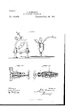
In the drawings, A is the main filling-foun tain, within which is located an agitator B, which is 'maintained continuously in motion by suitable mechanism (not shown) to effect the thorough mixture of the water admitted through the pipe C and the gas admitted through the pipe D. In this main filling fountain the pressure will be maintained at about one hundred and eighty pounds-the 8o pressure desirable for the beverage in portable fountains. l
E is a pipe leading from the filling-fountain A to the portable fountain-filling apparatus.
F and G are suitable controlling-cocks located therein.
I-I is an auxiliary fountain of smaller dimensions than the fountain A, and adapted to be putin communication therewith through the pipe I and regulator J.
K is a pipe which leads to the bottle-filling apparatus.
L is a pipe which leads back tothe gasometer and extends into the fountain II forv some distance, being provided in such extension with a float-valve II', which rises in the lower perforated extension of the pipe L, as the liquid in the fountain\rises until the desired height is reached, when communication vbetween-the gasometer and the auxiliary roo fountain Il through the pipe L is closed. This pipe L is also provided with a regulator M, similar to the regulator J. The regulator J, as shownvin the larger sectional view, Fig. 2, is fitted with a valve N, carried by a spindle O, which is guided in its movement in the valve-chamber by the collar P, located above the valve N of the width of the valve-charnber n, and held to place by the spiral spring Q. The valve N, as shown, controls communication between the pipe I and the auxiliary fountain H. The spindle O works in a recess R in the stem S. At the bottom the stem S is screw-threaded, so that by turning it the tension of the spring Qis increased or diminished, thereby regulating the point at which the valve will operate.
In Fig. 3 a sectional view is shown of the gas-regulator, and it will be seen that the same is similar in construction to regulator J. Therefore the same letters of reference have been employed. The pipe L, however, is connected somewhat differently, as shown.
The operation of my apparatus is as follows: During the operation of filling portable fountains at the high pressure, the regulators M and J may be closed, so that none of the carbonated liquid will enter the auxiliary reservoir Il. lVhen, however, it is desired to fill bottles, for instance, the regulators .I and M will be turned, so as to open communication, respectively, with the main filling fountain A and the gasometer. These regulators, when the auxiliary fountain is used for iilling bottles, arc set so as to operate at the pressure desired--say fifty pounds-and are so regulated that when the pressure within the auxiliary reservoir II reaches fifty pounds the spring of the regulator in connection with the pressure in the auxiliary fountain will exactly balance the pressure from the main filling-fountain A. The regulator will then close and remain closed as long as the pressure in the reservoir Il is at or over fifty pounds; but as soon as the pressure therein falls below that point the pressure from fountain A ,will open the regulator and admit the carbonated beverage until the pressure again reaches fifty pounds or over. Of course it will be understood that the pressure in the main filling-fountain A is maintained at the same point by the admission of gas from the generator by the use of a pump or by any other of the usual methods employed to maintain uniform pressure in the fountain. The automatic action of the regulater .l therefore permits the continuous use of the auxiliary fountain II, for at the moment pressure therein is reduced by withdrawing a portion of its contents for lilling purposes at that moment the regulator will open and a further supply will be admitted thereto. As the charged fluid enters the auxiliary reservoir a considerable amount of gas will be disengaged therefrom on account of the reduction in pressure. This gas accumulates in the upper portion of the reservoir, and whenever it rises above fifty pounds, or at Whatever point the regulator M may be set, it will open the said regulator and pass back to the gasometer, generator, or any other vessel at which the pressure is below the pressure in the auxiliary fountain.
Although I have only shown one. auxiliary fountain, it is obvious that another auxiliary fountain may be employed, where it is desirable, with the same apparatus to fill siphons as well as portable fountains and bottles.
I claim-- l. In an apparatus for filling vessels witlra carbonated liquid, the combination of a mam filling-reservoir containing the carbonated liquid at a given pressure, an auxiliary filling-fountain in communication with said main filling-fountain, and a regulator, substantially as set forth.
2. In an apparatus for filling vessels with a carbonated liquid, the combination of a main filling-reservoir, a mechanical agitator therein adapted to effect the mechanical mixture of the carbonic acid and water admitted thereto, and an auxiliary fountain in communication with said main filling-fountain and rcceivin g therefrom the carbonated liquid, and a regulator whereby the pressure may be maintained in the auxiliary reservoir at any given point, substantially as set forth.
3. In an apparatus for filling vessels with a carbonated liquid, the combination of a main filling-reservoir maintained at a given pressure, a mechanical agitator therein, an auxiliary filling-fountain communicating with said main filling-fountain, a regulator whereby thc pressure may be maintained therein at any given point, and an additional regulator whereby freed gas may be returned to a gasometcr, generator, or other vessel, substantially as set forth.
4c. In an apparatus for filling vessels with a carbonated liquid,the combination of a main filling-reservoir maintained at a given pressure, a mechanical agitator therein, an auxiliary fountain communicating with said main filling-fountain, an inlet-regulator, a gas-outlet regulator, and a Heat-valve in the latter regulator, substantially as set forth.
This specification signed and witnessed this -3d day of January, 1891.
JOHN ORMEROD. "Witnesses:
EUGENE COURAN, J. A. YOUNG.
Publications (1)
| Publication Number | Publication Date |
|---|---|
| US465976A true US465976A (en) | 1891-12-29 |
Family
ID=2534840
Family Applications (1)
| Application Number | Title | Priority Date | Filing Date |
|---|---|---|---|
| US465976D Expired - Lifetime US465976A (en) | Soda-water apparatus |
Country Status (1)
| Country | Link |
|---|---|
| US (1) | US465976A (en) |
-
0
- US US465976D patent/US465976A/en not_active Expired - Lifetime
Similar Documents
| Publication | Publication Date | Title |
|---|---|---|
| US2884943A (en) | Liquid-gas converter system | |
| US2371431A (en) | Beverage dispensing apparatus | |
| US1592305A (en) | Carbonating apparatus | |
| US1435883A (en) | Dispensing apparatus for mixing sirup and water | |
| US1087436A (en) | Combined liquid cooler and carbonator. | |
| US688586A (en) | Apparatus for drawing off liquids. | |
| US854390A (en) | Apparatus for carbonating liquids. | |
| US149135A (en) | Improvement in mineral-water-fountain feeders | |
| US394821A (en) | Oscar brtjnler | |
| US523872A (en) | Emil stahl | |
| US699249A (en) | Feed-regulating mechanism for liquids. | |
| US782815A (en) | Soda-fountain. | |
| US618550A (en) | winand | |
| US636076A (en) | Apparatus for storing hydrocarbons or other liquids. | |
| US655727A (en) | Carbonating apparatus. | |
| US302850A (en) | Acid-feeder for soda-water apparatus | |
| US1615175A (en) | Carbonating apparatus | |
| US101558A (en) | Self and john j | |
| US1394794A (en) | Combination carbonator and filler | |
| US191912A (en) | Improvement in carbonic-acid-gas generators | |
| US633057A (en) | Carbonating apparatus. | |
| US655300A (en) | Acetylene-gas generator. | |
| US673146A (en) | Carbonator. | |
| US478198A (en) | Carbonic-acid-gas generator | |
| US162986A (en) | Improvement in apparatus for drawing effervescent liquids |