US465956A - Pressure - Google Patents
Pressure Download PDFInfo
- Publication number
- US465956A US465956A US465956DA US465956A US 465956 A US465956 A US 465956A US 465956D A US465956D A US 465956DA US 465956 A US465956 A US 465956A
- Authority
- US
- United States
- Prior art keywords
- valve
- pressure
- springs
- diaphragm
- casting
- Prior art date
- Legal status (The legal status is an assumption and is not a legal conclusion. Google has not performed a legal analysis and makes no representation as to the accuracy of the status listed.)
- Expired - Lifetime
Links
- 238000005266 casting Methods 0.000 description 8
- 230000008878 coupling Effects 0.000 description 5
- 238000010168 coupling process Methods 0.000 description 5
- 238000005859 coupling reaction Methods 0.000 description 5
- 238000010276 construction Methods 0.000 description 3
- 210000002445 nipple Anatomy 0.000 description 1
Images
Classifications
-
- G—PHYSICS
- G05—CONTROLLING; REGULATING
- G05D—SYSTEMS FOR CONTROLLING OR REGULATING NON-ELECTRIC VARIABLES
- G05D16/00—Control of fluid pressure
- G05D16/04—Control of fluid pressure without auxiliary power
- G05D16/06—Control of fluid pressure without auxiliary power the sensing element being a flexible membrane, yielding to pressure, e.g. diaphragm, bellows, capsule
- G05D16/063—Control of fluid pressure without auxiliary power the sensing element being a flexible membrane, yielding to pressure, e.g. diaphragm, bellows, capsule the sensing element being a membrane
- G05D16/0644—Control of fluid pressure without auxiliary power the sensing element being a flexible membrane, yielding to pressure, e.g. diaphragm, bellows, capsule the sensing element being a membrane the membrane acting directly on the obturator
- G05D16/0655—Control of fluid pressure without auxiliary power the sensing element being a flexible membrane, yielding to pressure, e.g. diaphragm, bellows, capsule the sensing element being a membrane the membrane acting directly on the obturator using one spring-loaded membrane
- G05D16/0661—Control of fluid pressure without auxiliary power the sensing element being a flexible membrane, yielding to pressure, e.g. diaphragm, bellows, capsule the sensing element being a membrane the membrane acting directly on the obturator using one spring-loaded membrane characterised by the loading mechanisms of the membrane
-
- Y—GENERAL TAGGING OF NEW TECHNOLOGICAL DEVELOPMENTS; GENERAL TAGGING OF CROSS-SECTIONAL TECHNOLOGIES SPANNING OVER SEVERAL SECTIONS OF THE IPC; TECHNICAL SUBJECTS COVERED BY FORMER USPC CROSS-REFERENCE ART COLLECTIONS [XRACs] AND DIGESTS
- Y10—TECHNICAL SUBJECTS COVERED BY FORMER USPC
- Y10T—TECHNICAL SUBJECTS COVERED BY FORMER US CLASSIFICATION
- Y10T137/00—Fluid handling
- Y10T137/7722—Line condition change responsive valves
- Y10T137/7781—With separate connected fluid reactor surface
- Y10T137/7793—With opening bias [e.g., pressure regulator]
- Y10T137/7805—Through external pipe
- Y10T137/7806—Modified valve casing
Definitions
- Our invention relates to a pressure-regulator of that class in which the regulator is automatic; and it consists in the details of construction hereinafter referred to and claimed.
- Our main object is to simplify the construction of the regulator without impairing its efficiency in any way.
- A represents a casting or frame-work of any suitable construction or configuration adapted to support the operating parts.
- a coupling B From a projecting nipple on the lower end of this casting is supported a coupling B, to which is secured the inlet-pipe upon one side and the outlet-pipe upon the other.
- This coupling is provided with a valve-seat a, which receives the face of a valve Z), carried upon a stem 0, which passes through a stuffing-box on the lower end of the casting A.
- This valve controls the passage between the inlet and outlet and is operated, as hereinafter described.
- the main casting Depending from the circular flange d of'the main casting are rods f, which. carry upon their lower ends springs g. These springs are held by nuts hand a cross-bar 2, whichis connected to the stem of the valve. The tendency of these springs is to keep the valve raised from its seat, leaving the passage normally open, and the pressure exerted by these springs may be varied by adjusting the nuts h at the lower ends of the springs, the rods which support the nuts being screw-threaded for this purpose.
- the casting A is made in two parts,
- the upper part A being a shell which fits down over the corresponding part of the cast ing A, a diaphragm of suitable material, as
- substantially spherical chamber is formed by the two parts of the casting intersected by the diaphragm D.
- the stem of the valve passes up into the lower part of this chamber and carries upon its end a plate having a curved upper face, which is in contact with the under face of the diaphragm; but when .the' valve is open by reason of the pressure of the springs this plate will press the diaphragm upward.
Landscapes
- Physics & Mathematics (AREA)
- Fluid Mechanics (AREA)
- General Physics & Mathematics (AREA)
- Engineering & Computer Science (AREA)
- Automation & Control Theory (AREA)
- Safety Valves (AREA)
Description
(No Model.)
J. H. WERNER & S. FLORY. PRESSURE REGULATOR.
No. 465,956. Patented Dec. 29, 1891.
L\ I v f M766 T7z/e/z0/J- Wm gmfifi/w 3 wmaei Frg X 5 v UNITED STATES PATENT OFFICE.
JOHN H. WERNER AND SAMUEL FLORY, OF BANGOR, PENNSYLYANIA.
PRESSURE-REGULATOR.
SPECIFICATION formingpart of Letters Patent No. 465,956, dated December 29, 1891.
Application filed February 7, 1891. Serial No. 380,610. (No model.)
To all whom it may concern.-
Be it known that we, JOHN H. WVERNER and SAMUEL FLORY, citizens of the United States of America, residing at Bangor,in the county of Northampton and State of Pennsylvania, have invented certain new and useful Improvements in a Pressure-Regulator, of which the following is a specification.
Our invention relates to a pressure-regulator of that class in which the regulator is automatic; and it consists in the details of construction hereinafter referred to and claimed.
Our main object is to simplify the construction of the regulator without impairing its efficiency in any way.
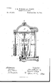
In the accompanying drawing we have shown our invention in.section,some of the parts being in side elevation.
In the drawing, A represents a casting or frame-work of any suitable construction or configuration adapted to support the operating parts. From a projecting nipple on the lower end of this casting is supported a coupling B, to which is secured the inlet-pipe upon one side and the outlet-pipe upon the other. This coupling is provided with a valve-seat a, which receives the face of a valve Z), carried upon a stem 0, which passes through a stuffing-box on the lower end of the casting A. This valve controls the passage between the inlet and outlet and is operated, as hereinafter described.
Depending from the circular flange d of'the main casting are rods f, which. carry upon their lower ends springs g. These springs are held by nuts hand a cross-bar 2, whichis connected to the stem of the valve. The tendency of these springs is to keep the valve raised from its seat, leaving the passage normally open, and the pressure exerted by these springs may be varied by adjusting the nuts h at the lower ends of the springs, the rods which support the nuts being screw-threaded for this purpose. The casting A is made in two parts,
the upper part A being a shell which fits down over the corresponding part of the cast ing A, a diaphragm of suitable material, as
at D, being interposed between the two. A
substantially spherical chamber is formed by the two parts of the casting intersected by the diaphragm D. The stem of the valve passes up into the lower part of this chamber and carries upon its end a plate having a curved upper face, which is in contact with the under face of the diaphragm; but when .the' valve is open by reason of the pressure of the springs this plate will press the diaphragm upward. In order that the pressure may be kept uniform and automatically close the valve when any excess of pressure is present we connect the chamber above the diaphragm with the coupling by means of a pipe Z, and thus when the pressure exceeds a determined amount for which the springs have been set to keep the valve open this excess of pressure will operate upon the diaphragm and be sufficientto overcome the pressureof the springs by reason of the greater surface exposed by the diaphragm than by the valve, and thus the valve will be closed or partially closed, and
in this way the pressure will be maintained.
We claim as our invention In combination with the casting A, acoupling carried thereby, inlet and outlet openings, a valve extending into said coupling, a cross-bar connected to the valve-stem, depending rods provided with springs in contact with said cross-bar, means for adjusting the tension of the springs, a chamber provided with a diaphragm, the valve-stem extending into said chamber and provided upon its end with a plate having a curved upper face in contact with the diaphragm, and a pipe connection between the coupling and the upper part of the chamber, substantially as described.
In testimonywhereof we aifix our signatures in presence of two witnesses.
JOHN H. WVERNER- SAMUEL FLORY.' Witnesses:
ADAM H. BRUoH, J OHN HOUSER.
Publications (1)
| Publication Number | Publication Date |
|---|---|
| US465956A true US465956A (en) | 1891-12-29 |
Family
ID=2534820
Family Applications (1)
| Application Number | Title | Priority Date | Filing Date |
|---|---|---|---|
| US465956D Expired - Lifetime US465956A (en) | Pressure |
Country Status (1)
| Country | Link |
|---|---|
| US (1) | US465956A (en) |
Cited By (2)
| Publication number | Priority date | Publication date | Assignee | Title |
|---|---|---|---|---|
| US2425284A (en) * | 1943-08-07 | 1947-08-05 | Spence Engineering Company Inc | Valve |
| US2854990A (en) * | 1955-10-06 | 1958-10-07 | Albert J Granberg | Flow control valve assembly responsive to downstream pressure |
-
0
- US US465956D patent/US465956A/en not_active Expired - Lifetime
Cited By (2)
| Publication number | Priority date | Publication date | Assignee | Title |
|---|---|---|---|---|
| US2425284A (en) * | 1943-08-07 | 1947-08-05 | Spence Engineering Company Inc | Valve |
| US2854990A (en) * | 1955-10-06 | 1958-10-07 | Albert J Granberg | Flow control valve assembly responsive to downstream pressure |
Similar Documents
| Publication | Publication Date | Title |
|---|---|---|
| US571833A (en) | Regulating-valve | |
| US436235A (en) | Fluid-pressure regulator | |
| US744297A (en) | Fluid-pressure regulator. | |
| US729271A (en) | Gas-governor. | |
| US930640A (en) | Gas-regulator. | |
| US670539A (en) | Pressure-regulator. | |
| US662489A (en) | Steam-trap. | |
| US722355A (en) | Reducing-valve. | |
| US494984A (en) | Feed-regulator | |
| US408071A (en) | Gas-governor | |
| US558598A (en) | Feed-water regulator | |
| US663158A (en) | Gas-regulator for steam-boilers. | |
| US788240A (en) | Pressure-reducing valve. | |
| US190442A (en) | Improvement in automatic water-pipe pressure cut-offs | |
| US697303A (en) | Ram. | |
| US404400A (en) | Boiler feed-regulator | |
| US626217A (en) | Pump-regulator | |
| US613737A (en) | Flu id-pressure-regulating valve | |
| US373616A (en) | Steam and gas governor | |
| US555540A (en) | Boiler-pump regulator | |
| US216834A (en) | Improvement in steam-valves | |
| US165767A (en) | Improvement in gas and water regulators | |
| US246952A (en) | Biedsill holly | |
| US481098A (en) | Steam-trap | |
| US146335A (en) | Improvement in automatic water-supply regulators for cisterns, tanks |