US465928A - Latch - Google Patents
Latch Download PDFInfo
- Publication number
- US465928A US465928A US465928DA US465928A US 465928 A US465928 A US 465928A US 465928D A US465928D A US 465928DA US 465928 A US465928 A US 465928A
- Authority
- US
- United States
- Prior art keywords
- latch
- bar
- saddle
- shell
- lock
- Prior art date
- Legal status (The legal status is an assumption and is not a legal conclusion. Google has not performed a legal analysis and makes no representation as to the accuracy of the status listed.)
- Expired - Lifetime
Links
- 238000010276 construction Methods 0.000 description 2
Images
Classifications
-
- E—FIXED CONSTRUCTIONS
- E05—LOCKS; KEYS; WINDOW OR DOOR FITTINGS; SAFES
- E05B—LOCKS; ACCESSORIES THEREFOR; HANDCUFFS
- E05B83/00—Vehicle locks specially adapted for particular types of wing or vehicle
- E05B83/02—Locks for railway freight-cars, freight containers or the like; Locks for the cargo compartments of commercial lorries, trucks or vans
-
- Y—GENERAL TAGGING OF NEW TECHNOLOGICAL DEVELOPMENTS; GENERAL TAGGING OF CROSS-SECTIONAL TECHNOLOGIES SPANNING OVER SEVERAL SECTIONS OF THE IPC; TECHNICAL SUBJECTS COVERED BY FORMER USPC CROSS-REFERENCE ART COLLECTIONS [XRACs] AND DIGESTS
- Y10—TECHNICAL SUBJECTS COVERED BY FORMER USPC
- Y10T—TECHNICAL SUBJECTS COVERED BY FORMER US CLASSIFICATION
- Y10T292/00—Closure fasteners
- Y10T292/08—Bolts
- Y10T292/096—Sliding
- Y10T292/1006—Gravity actuated
- Y10T292/1007—Operating means
- Y10T292/101—Cam
-
- Y—GENERAL TAGGING OF NEW TECHNOLOGICAL DEVELOPMENTS; GENERAL TAGGING OF CROSS-SECTIONAL TECHNOLOGIES SPANNING OVER SEVERAL SECTIONS OF THE IPC; TECHNICAL SUBJECTS COVERED BY FORMER USPC CROSS-REFERENCE ART COLLECTIONS [XRACs] AND DIGESTS
- Y10—TECHNICAL SUBJECTS COVERED BY FORMER USPC
- Y10T—TECHNICAL SUBJECTS COVERED BY FORMER US CLASSIFICATION
- Y10T292/00—Closure fasteners
- Y10T292/08—Bolts
- Y10T292/096—Sliding
- Y10T292/1014—Operating means
- Y10T292/1022—Rigid
- Y10T292/1031—Swinging catch
Definitions
- Our invention relates to improvements in combined locks and latches, and the object is to provide a simple, cheap, and durable latch and lock.
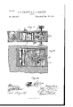
- FIG. II is a longitudinal sectional View on the line .fr .fr of Fig. I
- Fig. III is a detail view of the latch-bar.
- a saddle B is journaled Within the inclosing case or shell, and to the pivots or journals thereof are attached suitable knobs or handles C.
- the saddle B is provided with a downwardly-projecting portion D, which serves to balance and hold the saddle in the proper position.
- On this saddle C is supported the latch-bar E.
- This latch-bar has its forward end reduced, and said reduced port-ion is extended or projected through a suitable aperture in the front wall of the inclosing casing or shell A, and on its lower side said bar is provided with a notch or recess c, in which the saddle BI (its.
- said latch-bar On its upper side, near the rear or inner end thereof, said latch-bar is cut away to form a stop or shoulder E, and the lower surface or edge of the latch-bar is curved from the notch or recess c to the inner end thereof, as shown. l The latch-baiis prevented from moving forward beyond a certain distance by reason of the lugs or shoulders f f', formed on the upper and lower sides thereof, which are adapted to come in contact with the front wall of the casing A.
- a shaft G is arranged transversely across the interior vof the casing or shell A in rear of the saddle B, and to this .shaft is attached a projecting stud or block g. To one end of the shaft G is attached a thumb-piece II, by which the shaft is turned and the stud g forced against the shoulder F to lock the latch bar against rearward movement, as shown in Fig. II.
- an audible signal which comprises a gong K, attached to the inner side of the rear Wall of the casing or shell A, and a striking-hammer L, which is attached to a transverse shaft M,
- rlhis striking-bar is operated by a handle II, which extends through a door to which the lock is attached, and is provided at its outer end with a knob N.
- the operation of our invent-ion is as follows: The latch-bar is reciprocated to fasten or unfasten the vdoor by operating eitherone of the knobs or handles O. To lock the door, the latch-bar is moved into the position shown in Fig. II, and the shaft G turned to force the stud g carried thereby against the shoulder F on the latch-bar, and thus hold the latter firmly in place.
- a combined lock and latch In a combined lock and latch, the combination, with an inclosing case or shell, of a weighted saddle journaled in the side walls of said Case or shell, a latch-bar provided ou its lower edge with a notch o1' recess in which the eross-pece of the saddle ts, and a lookng-bar journaled in the side walls of the inclosing ease or shell and adapted to be thrown into engagement with the latclbbfw, as and for the purpose described.
Landscapes
- Lock And Its Accessories (AREA)
Description
(No Medel.)
J. S. HEADEN 8e 0. L. BEASLEY. LATCH.
190.495,929. Patented Dee. 29, 1891.
.-1 n l A NITED STATES PATENT OFFICE.
JOI-IN SAMUEL I-IEADEN AND OLIVER LOVELL BEASLEY, OF PLEASANT HILL, MISSOURI.
LATCH.
SPECIFICATION forming part of Letters Patent No. 465,928, dated December 29, 1891.
Application filed May 20, 1891. Serial No. 393,443. (No model.)
To all whom it may concern:
Be it known that we, J oHN SAMUEL HEADEN and OLIVER LovELL BEASLEY, citizens of the United States, residing at Pleasant Hill, in the county of Cass and VState of Missouri, have invented certain new and useful Improvements in Combined Locks and Latches; and we do hereby declare the following to be a full, clear, and exact description of the invention, such as will enable others skilled in the art to which it appertains to make and use the same.
Our invention relates to improvements in combined locks and latches, and the object is to provide a simple, cheap, and durable latch and lock. Y
With these ends in view our invention consists of the peculiar construction and arrangement of parts and combination of devices, as will be fully pointed out hereinafter. Y
To enable others to more readily understand our invention, we have illustrated the same inthe accompanying drawings, in Which- Figure I is a section through a door provided With our improved latch, showing the operating parts of the lock in plan view. Fig. II is a longitudinal sectional View on the line .fr .fr of Fig. I, and Fig. III is a detail view of the latch-bar.
Like letters of reference denote corresponding parts in the several figures of the drawings, referring to which- A designates the outer inclosing case or shell of our 'improved lock. A saddle B is journaled Within the inclosing case or shell, and to the pivots or journals thereof are attached suitable knobs or handles C. The saddle B is provided with a downwardly-projecting portion D, which serves to balance and hold the saddle in the proper position. On this saddle C is supported the latch-bar E. This latch-bar has its forward end reduced, and said reduced port-ion is extended or projected through a suitable aperture in the front wall of the inclosing casing or shell A, and on its lower side said bar is provided with a notch or recess c, in which the saddle BI (its. On its upper side, near the rear or inner end thereof, said latch-bar is cut away to form a stop or shoulder E, and the lower surface or edge of the latch-bar is curved from the notch or recess c to the inner end thereof, as shown. lThe latch-baiis prevented from moving forward beyond a certain distance by reason of the lugs or shoulders f f', formed on the upper and lower sides thereof, which are adapted to come in contact with the front wall of the casing A.
A shaft G is arranged transversely across the interior vof the casing or shell A in rear of the saddle B, and to this .shaft is attached a projecting stud or block g. To one end of the shaft G is attached a thumb-piece II, by which the shaft is turned and the stud g forced against the shoulder F to lock the latch bar against rearward movement, as shown in Fig. II.
We have also provided our lock with an audible signal, which comprises a gong K, attached to the inner side of the rear Wall of the casing or shell A, and a striking-hammer L, which is attached to a transverse shaft M,
journaled in the side walls of the casing A near the rear thereof. rlhis striking-bar is operated by a handle II, which extends through a door to which the lock is attached, and is provided at its outer end with a knob N.
The operation of our invent-ion is as follows: The latch-bar is reciprocated to fasten or unfasten the vdoor by operating eitherone of the knobs or handles O. To lock the door, the latch-bar is moved into the position shown in Fig. II, and the shaft G turned to force the stud g carried thereby against the shoulder F on the latch-bar, and thus hold the latter firmly in place.
W'e are aware that changes in the form and proportion of parts and details of construction of the devices herein shown `and described as an embodiment of our invention can be made without departing from the spirit or sacrificing the advantages thereof, and we therefore reserve the right to makey such changes as fairly fall within the scope of our invention.
Having thus described our invention, what We claim as new, and desire to secure by Letters Patent, is-
In a combined lock and latch, the combination, with an inclosing case or shell, of a weighted saddle journaled in the side walls of said Case or shell, a latch-bar provided ou its lower edge with a notch o1' recess in which the eross-pece of the saddle ts, and a lookng-bar journaled in the side walls of the inclosing ease or shell and adapted to be thrown into engagement with the latclbbfw, as and for the purpose described.
In testimony whereof We am); our signatures in presence of two witnesses.
J OI-IN SAMUEL HEADEN. OLIVER LOVELL BEASLEY. Witnesses:
W. K. WILLIAMs, H. J ERARD.
Publications (1)
| Publication Number | Publication Date |
|---|---|
| US465928A true US465928A (en) | 1891-12-29 |
Family
ID=2534792
Family Applications (1)
| Application Number | Title | Priority Date | Filing Date |
|---|---|---|---|
| US465928D Expired - Lifetime US465928A (en) | Latch |
Country Status (1)
| Country | Link |
|---|---|
| US (1) | US465928A (en) |
-
0
- US US465928D patent/US465928A/en not_active Expired - Lifetime
Similar Documents
| Publication | Publication Date | Title |
|---|---|---|
| US188308A (en) | Improvement in combined latqh and bolt | |
| US195611A (en) | Improvement in lock-cocks | |
| US389110A (en) | Door-catch | |
| US219977A (en) | Improvement in latches | |
| US169030A (en) | Improvement in sash-fasteners | |
| US619524A (en) | Adelbert j | |
| US798209A (en) | Knob for doors and latches. | |
| US159281A (en) | Improvement in door-latches | |
| US180239A (en) | Improvement in knob-latches | |
| US639515A (en) | Latch. | |
| US185752A (en) | Improvement in knob-latches | |
| US193639A (en) | Improvement in wicket-slides for car-doors | |
| US269097A (en) | Latch | |
| US555688A (en) | Box-fastener | |
| US137841A (en) | Improvement in door-bolts | |
| US475270A (en) | Territory | |
| US470412A (en) | James roche | |
| US949880A (en) | Hasp. | |
| US140338A (en) | Improvement in trunk-fasteners | |
| US195798A (en) | Improvement in gate-latches | |
| US187015A (en) | Improvement in knob-levers for mortise-latches | |
| US435555A (en) | The nohris peters co | |
| US214773A (en) | Improvement in locks for doors | |
| US356155A (en) | Latch | |
| US814186A (en) | Knob-latch. |