US4657215A - Mounting assembly for heater thermstat control - Google Patents
Mounting assembly for heater thermstat control Download PDFInfo
- Publication number
- US4657215A US4657215A US06/689,659 US68965985A US4657215A US 4657215 A US4657215 A US 4657215A US 68965985 A US68965985 A US 68965985A US 4657215 A US4657215 A US 4657215A
- Authority
- US
- United States
- Prior art keywords
- bracket
- tank
- legs
- thermostat control
- thermostat
- Prior art date
- Legal status (The legal status is an assumption and is not a legal conclusion. Google has not performed a legal analysis and makes no representation as to the accuracy of the status listed.)
- Expired - Lifetime
Links
- 210000005069 ears Anatomy 0.000 claims abstract description 9
- 239000000463 material Substances 0.000 claims description 3
- 238000010438 heat treatment Methods 0.000 claims description 2
- XLYOFNOQVPJJNP-UHFFFAOYSA-N water Substances O XLYOFNOQVPJJNP-UHFFFAOYSA-N 0.000 abstract description 4
- 230000000712 assembly Effects 0.000 description 3
- 238000000429 assembly Methods 0.000 description 3
- 238000010276 construction Methods 0.000 description 2
- 230000000694 effects Effects 0.000 description 2
- 238000009434 installation Methods 0.000 description 2
- OKTJSMMVPCPJKN-UHFFFAOYSA-N Carbon Chemical compound [C] OKTJSMMVPCPJKN-UHFFFAOYSA-N 0.000 description 1
- 229910000639 Spring steel Inorganic materials 0.000 description 1
- 229910052799 carbon Inorganic materials 0.000 description 1
- 230000004048 modification Effects 0.000 description 1
- 238000012986 modification Methods 0.000 description 1
Images
Classifications
-
- F—MECHANICAL ENGINEERING; LIGHTING; HEATING; WEAPONS; BLASTING
- F24—HEATING; RANGES; VENTILATING
- F24H—FLUID HEATERS, e.g. WATER OR AIR HEATERS, HAVING HEAT-GENERATING MEANS, e.g. HEAT PUMPS, IN GENERAL
- F24H9/00—Details
- F24H9/20—Arrangement or mounting of control or safety devices
- F24H9/2007—Arrangement or mounting of control or safety devices for water heaters
- F24H9/2014—Arrangement or mounting of control or safety devices for water heaters using electrical energy supply
- F24H9/2021—Storage heaters
Definitions
- This invention relates to mounting assemblies for temperature controls for heater tanks and, more particularly, to assemblies for mounting thermostat controls on the outer wall of the storage tanks of electric water heaters.
- the mounting assembly of the present invention is an improvement of the assembly shown in U.S. Pat. No. 4,399,971.
- the mounting assembly comprises a first or tank bracket including a body having an opening adapted to lockingly fit over the heater tank spud and a pair of laterally-spaced legs extending from the body and having a bent upper end portion adapted to apply spring pressure toward the tank outer wall when the first bracket is locked on the tank spud.
- Each of the legs includes an elongated slot in the upper end portion.
- the mounting assembly also includes a second or thermostat bracket carrying the thermostat control and having a pair of laterally-spaced, upstanding ears adapted to fit beneath the upper end portion of the legs.
- Each of the ears includes a nib received in a leg slot to interlock the two brackets.
- the nib has an upper edge which engages the upper end of the slot and is arranged to urge the thermostat bracket into firmer contact with the tank in response to upward vertical movement of the thermostat bracket relative to the tank bracket.
- the assembly is further characterized by a retaining lip on the tank bracket which is located between the legs of the bracket and positioned to bear against the end wall of the thermostat control when the parts are in assembled position and an outward horizontal load is applied.
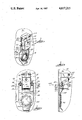
- FIG. 1 is a perspective view of a mounting assembly of the invention with a thermostatic control installed on a storage tank of an electric water heater;
- FIG. 2 is a top plan view of the mounting assembly shown in FIG. 1;
- FIG. 3 is an enlarged, fragmentary, partially sectioned, side view of the mounting assembly shown in FIG. 1.
- a storage tank 10 (illustrated fragmentarily in FIG. 1) for an electric water heater including an internally threaded spud 12 which receives an electrical heating element (not shown).
- a conventional thermostat control 14 is held in firm contact with the outer surface 16 of the heater storage tank 10 by a mounting assembly 18 embodying the invention.
- the thermostat control 14 includes an adjustment knob 19 and a temperature-indicating dial 20.
- the thermostat control 14 also includes a pair of electrical terminals 21 and can be connected to the supply wiring via a pair of pigtail leads 22 fastened on the terminals 21.
- the mounting assembly 18 includes a first or tank bracket 24 and a second or thermostat bracket 26 carrying the thermostat control 14.
- the tank bracket 24 is made from a spring material (e.g., 0.020-inch high carbon spring steel), has a main body 28 including a circular opening 30 adapted to lockingly fit over the tank spud 12, and has a pair of laterally-spaced fingers or legs 32 extending from the body 28.
- the opening 30 is surrounded by a plurality of circumferentially-spaced, partially out-turned leaves 34 which, prior to installation, define a circular opening having an inside diameter somewhat smaller than the outside diameter of the tank spud 12.
- the tank bracket 24 is installed by forcing the leaves 34 down over the tank spud 12 and the leaves 34 thereafter bite into or wedge onto the tank spud 12 to secure the tank bracket 24 in place.
- the legs 32 on the tank bracket 24 have a bent upper end portion 36 adapted to apply spring pressure, via a bight portion 37, in a direction toward the outer surface 16 of the storage tank 10 when the tank bracket 24 is installed on the tank spud 12.
- the upper end portion 36 of each leg 32 includes a narrow, elongated slot 38 having an upper end 40.
- the thermostat bracket 26 includes a pair of laterally-spaced, upstanding ears 42 adapted to fit beneath the upper end portion 36 of the legs 32.
- the lower end portion of each ear 42 is in the form of a nib 44 which extends through the slot 38 in a leg 32 to interlock the thermostat bracket 26 with the tank bracket 24.
- the nib 44 has an outer tip portion 46 and an inclined lower edge 48 which serves as a camming surface for the bight portion 37 on the leg 32 as the ears are moved (vertically downwardly) beneath the legs 32 to interlock the thermostat bracket 26 with the tank bracket 24.
- the bight portions 37 apply a spring pressure on a generally straight ledge 50 on each ear 42 and thereby hold the back side of the thermostat bracket 26 in firm contact with the outer surface 16 of the storage tank 10.
- the thermostat bracket 26 can include one or more openings (not shown) in the back side for permitting direct exposure of the temperature sensitive element (not shown) of the thermostat control 14 to the outer surface 16 of the storage tank 10.
- the tank bracket 24 is provided with a retaining lip portion 39.
- Lip portion 39 is located intermediate legs 32 and angles upwardly from the face of the tank bracket 24.
- retaining lip portion 39 will bear against the end wall 41 of thermostat control 14.
- Lip 39 is dimensioned so that when the tank bracket 24 is pressed into its assembled position on spud 12 and an outward horizontal load is applied, the lip 39 will be bowed slightly downwardly to thus apply a spring pressure on the wall 41 of the thermostatic control 14. The overall effect is to provide a secure clamping action between the parts to thereby virtually eliminate inadvertent disconnection of the thermostat control 14 from the tank bracket 24.
- the upper edge 52 of the nib 44 is downwardly inclined in a direction from the tip portion 46 toward the storage tank 10. While this incline can vary somewhat, the upper edge 52 preferably extends from the tip portion 46 at an angle of about 10° relative to a plane (designated by reference numeral 54) extending generally perpendicularly to the center line of the storage tank 10 as illustrated in FIG. 2.
- a plane designated by reference numeral 54
- pulling on the pigtail leads 22 does not cause the thermostat bracket 26 to become disconnected from the tank bracket 24. Instead, this pulling movement causes a camming effect between the upper edge 52 of the nib 46 and the front edge 40 of the slot 38 which tends to move the thermostat bracket 26 into firmer contact with the outer wall of the storage tank.
- the tank bracket 24 is first installed by forcing the leaves 34 down over the tank spud 12.
- the thermostat bracket 26 carrying the thermostat control 14 is interlocked with the tank bracket 24 by moving the lower edges 48 of the nibs 44 into engagement with the upper ends of the legs 32 and pushing downward on the thermostat bracket 26 until the nibs 44 snap into the slots 38.
- the bight portions 37 of the legs 32 bear against the ear ledges 50 and keep the thermostat bracket 26 in firm contact with the storage tank 10 and the nibs 44 cooperate with the slots 38 to prevent undue vertical and lateral movement.
- Retaining lip 39 provides an additional holding force as explained previously.
- a faulty thermostat control can be removed by lifting the legs 32 sufficiently to disengage the nibs 44 from the slots 38. As indicated previously, the combined holding action of legs 32 and lip 39 prevent the pulling of the thermostat from underneath the tank bracket 24 with other than the application of a substantial pulling force (in excess of 5 lbs).
Landscapes
- Engineering & Computer Science (AREA)
- Physics & Mathematics (AREA)
- Thermal Sciences (AREA)
- Chemical & Material Sciences (AREA)
- Combustion & Propulsion (AREA)
- Mechanical Engineering (AREA)
- General Engineering & Computer Science (AREA)
- Thermally Actuated Switches (AREA)
Abstract
Description
Claims (2)
Priority Applications (2)
| Application Number | Priority Date | Filing Date | Title |
|---|---|---|---|
| US06/689,659 US4657215A (en) | 1985-01-08 | 1985-01-08 | Mounting assembly for heater thermstat control |
| CA000480939A CA1234860A (en) | 1985-01-08 | 1985-05-07 | Mounting assembly for heater thermostat control |
Applications Claiming Priority (1)
| Application Number | Priority Date | Filing Date | Title |
|---|---|---|---|
| US06/689,659 US4657215A (en) | 1985-01-08 | 1985-01-08 | Mounting assembly for heater thermstat control |
Publications (1)
| Publication Number | Publication Date |
|---|---|
| US4657215A true US4657215A (en) | 1987-04-14 |
Family
ID=24769399
Family Applications (1)
| Application Number | Title | Priority Date | Filing Date |
|---|---|---|---|
| US06/689,659 Expired - Lifetime US4657215A (en) | 1985-01-08 | 1985-01-08 | Mounting assembly for heater thermstat control |
Country Status (2)
| Country | Link |
|---|---|
| US (1) | US4657215A (en) |
| CA (1) | CA1234860A (en) |
Cited By (10)
| Publication number | Priority date | Publication date | Assignee | Title |
|---|---|---|---|---|
| US5022624A (en) * | 1990-02-06 | 1991-06-11 | Hill Joe A | Adjustable support for hot water tanks, or the like |
| US5220638A (en) * | 1991-09-30 | 1993-06-15 | Mor-Flo Industries, Inc. | Water heater with an improved thermostat mounting and a method of making such water heaters |
| US20040200507A1 (en) * | 2003-04-10 | 2004-10-14 | Maytag Corporation | Bracket for dishwasher tub |
| US20070246556A1 (en) * | 2006-03-27 | 2007-10-25 | Patterson Wade C | Water heating system and method |
| US20070246551A1 (en) * | 2004-08-26 | 2007-10-25 | Phillips Terry G | Modular control system and method for water heaters |
| US20070248143A1 (en) * | 2006-03-27 | 2007-10-25 | Phillips Terry G | Water heating systems and methods |
| US20090293816A1 (en) * | 2005-05-11 | 2009-12-03 | Patterson Wade C | System and method for estimating and indicating temperature characteristics of temperature controlled liquids |
| US20100082134A1 (en) * | 2004-08-26 | 2010-04-01 | Phillips Terry G | Modular control system and method for a water heater |
| US9282654B2 (en) | 2014-05-06 | 2016-03-08 | Honeywell International Inc. | HVAC controller with air flow barrier |
| US9395101B2 (en) | 2014-06-11 | 2016-07-19 | Miclau-S.R.I. Inc | Pressure clamp adapter for mounting a thermistor on a thermostat control bracket |
Families Citing this family (1)
| Publication number | Priority date | Publication date | Assignee | Title |
|---|---|---|---|---|
| CA2158120C (en) * | 1995-09-12 | 2006-04-11 | John Tracey Demaline | Hot water controller |
Citations (7)
| Publication number | Priority date | Publication date | Assignee | Title |
|---|---|---|---|---|
| US2575150A (en) * | 1949-02-17 | 1951-11-13 | White Products Company | Thermostat mounting assembly for hot-water heaters and the like |
| US2686031A (en) * | 1950-10-11 | 1954-08-10 | Adrian Medert | Mounting bracket for thermostatic switches |
| CA676099A (en) * | 1963-12-17 | G. Buchwald William | Electric blanket control unit holder | |
| US3276599A (en) * | 1964-09-16 | 1966-10-04 | Therm O Disc Inc | Mounting assemblies |
| US3883717A (en) * | 1974-04-01 | 1975-05-13 | Michael J Delpercio | Mounting installation for temperature sensing switch |
| US3992608A (en) * | 1975-10-01 | 1976-11-16 | A. O. Smith Corporation | Combination attachment for water heater electric heating element and thermostat |
| US4399971A (en) * | 1981-01-12 | 1983-08-23 | Apcom, Inc. | Mounting assembly for heater thermostat control |
-
1985
- 1985-01-08 US US06/689,659 patent/US4657215A/en not_active Expired - Lifetime
- 1985-05-07 CA CA000480939A patent/CA1234860A/en not_active Expired
Patent Citations (7)
| Publication number | Priority date | Publication date | Assignee | Title |
|---|---|---|---|---|
| CA676099A (en) * | 1963-12-17 | G. Buchwald William | Electric blanket control unit holder | |
| US2575150A (en) * | 1949-02-17 | 1951-11-13 | White Products Company | Thermostat mounting assembly for hot-water heaters and the like |
| US2686031A (en) * | 1950-10-11 | 1954-08-10 | Adrian Medert | Mounting bracket for thermostatic switches |
| US3276599A (en) * | 1964-09-16 | 1966-10-04 | Therm O Disc Inc | Mounting assemblies |
| US3883717A (en) * | 1974-04-01 | 1975-05-13 | Michael J Delpercio | Mounting installation for temperature sensing switch |
| US3992608A (en) * | 1975-10-01 | 1976-11-16 | A. O. Smith Corporation | Combination attachment for water heater electric heating element and thermostat |
| US4399971A (en) * | 1981-01-12 | 1983-08-23 | Apcom, Inc. | Mounting assembly for heater thermostat control |
Cited By (18)
| Publication number | Priority date | Publication date | Assignee | Title |
|---|---|---|---|---|
| US5022624A (en) * | 1990-02-06 | 1991-06-11 | Hill Joe A | Adjustable support for hot water tanks, or the like |
| US5220638A (en) * | 1991-09-30 | 1993-06-15 | Mor-Flo Industries, Inc. | Water heater with an improved thermostat mounting and a method of making such water heaters |
| US20040200507A1 (en) * | 2003-04-10 | 2004-10-14 | Maytag Corporation | Bracket for dishwasher tub |
| US7146993B2 (en) | 2003-04-10 | 2006-12-12 | Maytag Corporation | Bracket for dishwasher tub |
| US8977791B2 (en) | 2004-08-26 | 2015-03-10 | A. O. Smith Corporation | Modular control system and method for a water heater |
| US20070246551A1 (en) * | 2004-08-26 | 2007-10-25 | Phillips Terry G | Modular control system and method for water heaters |
| US10240817B2 (en) | 2004-08-26 | 2019-03-26 | A. O. Smith Corporation | Modular control system and method for water heaters |
| US20100082134A1 (en) * | 2004-08-26 | 2010-04-01 | Phillips Terry G | Modular control system and method for a water heater |
| US9057534B2 (en) | 2004-08-26 | 2015-06-16 | A. O. Smith Corporation | Modular control system and method for water heaters |
| US8660701B2 (en) | 2004-08-26 | 2014-02-25 | A. O. Smith Corporation | Modular control system and method for water heaters |
| US20090293816A1 (en) * | 2005-05-11 | 2009-12-03 | Patterson Wade C | System and method for estimating and indicating temperature characteristics of temperature controlled liquids |
| US8064757B2 (en) | 2005-05-11 | 2011-11-22 | A. O. Smith Corporation | System and method for estimating and indicating temperature characteristics of temperature controlled liquids |
| US20070246556A1 (en) * | 2006-03-27 | 2007-10-25 | Patterson Wade C | Water heating system and method |
| US8887671B2 (en) * | 2006-03-27 | 2014-11-18 | A. O. Smith Corporation | Water heating systems and methods |
| US8245669B2 (en) | 2006-03-27 | 2012-08-21 | A. O. Smith Corporation | Water heating systems and methods |
| US20070248143A1 (en) * | 2006-03-27 | 2007-10-25 | Phillips Terry G | Water heating systems and methods |
| US9282654B2 (en) | 2014-05-06 | 2016-03-08 | Honeywell International Inc. | HVAC controller with air flow barrier |
| US9395101B2 (en) | 2014-06-11 | 2016-07-19 | Miclau-S.R.I. Inc | Pressure clamp adapter for mounting a thermistor on a thermostat control bracket |
Also Published As
| Publication number | Publication date |
|---|---|
| CA1234860A (en) | 1988-04-05 |
Similar Documents
| Publication | Publication Date | Title |
|---|---|---|
| US4657215A (en) | Mounting assembly for heater thermstat control | |
| US4164618A (en) | Plug-in service pole assembly | |
| US4399971A (en) | Mounting assembly for heater thermostat control | |
| US5364051A (en) | Locator clip | |
| JPH07107347B2 (en) | Fixing device for blind lamellas | |
| US4974804A (en) | Hold down clip for electric range surface elements | |
| US3626151A (en) | Protector shield | |
| US5174767A (en) | Conductor connector assembly | |
| US2686031A (en) | Mounting bracket for thermostatic switches | |
| US2972788A (en) | Swinging door support | |
| US2268446A (en) | Fluorescent lamp socket | |
| US4907772A (en) | Universal clamp for aquarium tank | |
| US3056012A (en) | Heating unit | |
| CA1051963A (en) | Socket assembly for plug-in heating elements for stove tops | |
| US4906819A (en) | Hold-down clip for electric range surface elements | |
| US3883717A (en) | Mounting installation for temperature sensing switch | |
| JPS633411B2 (en) | ||
| JPH0411988B2 (en) | ||
| CN112240588A (en) | Oil box assembly for integrated cooker and integrated cooker | |
| JPS5843160Y2 (en) | Temperature sensor mounting device | |
| US1971970A (en) | Automatic control for electrical appliances | |
| CN220020985U (en) | Temperature controller | |
| CN209877012U (en) | Electromagnetic oven with reliable temperature measurement | |
| US4646054A (en) | Thermal switch | |
| CN111184438B (en) | Liquid heating vessel and control unit for a liquid heating vessel |
Legal Events
| Date | Code | Title | Description |
|---|---|---|---|
| AS | Assignment |
Owner name: APCOM, INC., FRAKLIN, TN. 37065-0687, CORP. OF TN Free format text: ASSIGNMENT OF ASSIGNORS INTEREST.;ASSIGNOR:MURPHY, MARK A.;REEL/FRAME:004356/0099 Effective date: 19850102 |
|
| AS | Assignment |
Owner name: BANKERS TRUST COMPANY, 280 PARK AVENUE, NEW YORK, Free format text: SECURITY INTEREST;ASSIGNOR:STATE INDUSTRIES, INC., A CORP OF TN;REEL/FRAME:004648/0541 Effective date: 19861028 Owner name: BANKERS TRUST COMPANY, 280 PARK AVENUE, NEW YORK, Free format text: SECURITY INTEREST;ASSIGNOR:STATE INDUSTRIES, INC. A TN CORP.;REEL/FRAME:004648/0558 Effective date: 19861028 Owner name: BANKERS TRUST COMPANY, A CORP OF NY,NEW YORK Free format text: SECURITY INTEREST;ASSIGNOR:STATE INDUSTRIES, INC., A CORP OF TN;REEL/FRAME:004648/0541 Effective date: 19861028 Owner name: BANKERS TRUST COMPANY, A CORP OF NY,NEW YORK Free format text: SECURITY INTEREST;ASSIGNOR:STATE INDUSTRIES, INC. A TN CORP.;REEL/FRAME:004648/0558 Effective date: 19861028 |
|
| STCF | Information on status: patent grant |
Free format text: PATENTED CASE |
|
| FPAY | Fee payment |
Year of fee payment: 4 |
|
| AS | Assignment |
Owner name: STATE INDUSTRIES, INC. A CORP. OF TN Free format text: RELEASED BY SECURED PARTY;ASSIGNOR:BANKERS TRUST COMPANY, A CORP. OF NY;REEL/FRAME:005903/0116 Effective date: 19911009 Owner name: STATE INDUSTRIES, INC.,TENNESSEE Free format text: RELEASED BY SECURED PARTY;ASSIGNOR:BANKERS TRUST COMPANY;REEL/FRAME:005903/0116 Effective date: 19911009 |
|
| FPAY | Fee payment |
Year of fee payment: 8 |
|
| AS | Assignment |
Owner name: APCOM, INC., TENNESSEE Free format text: RELEASE OF INTEREST IN PATENTS;ASSIGNOR:MERCANTILE BANK OF ST. LOUIS, N.A.;REEL/FRAME:008683/0860 Effective date: 19970829 Owner name: NATIONSBANK, N.A., GEORGIA Free format text: SECURITY AGREEMENT;ASSIGNOR:APCOM, INC.;REEL/FRAME:008683/0863 Effective date: 19970829 |
|
| FPAY | Fee payment |
Year of fee payment: 12 |
|
| AS | Assignment |
Owner name: APCOM, INC., TENNESSEE Free format text: RELEASE OF SECURITY INTEREST;ASSIGNOR:BANK OF AMERICA, N.A.;REEL/FRAME:012641/0820 Effective date: 20011228 |