US4657158A - Device for feeding electronic components packed in tape to a pick-up position - Google Patents

Device for feeding electronic components packed in tape to a pick-up position Download PDF

Info

Publication number
US4657158A
US4657158A US06/630,563 US63056384A US4657158A US 4657158 A US4657158 A US 4657158A US 63056384 A US63056384 A US 63056384A US 4657158 A US4657158 A US 4657158A
Authority
US
United States
Prior art keywords
feeding
tape
driving
slide
reel
Prior art date
Legal status (The legal status is an assumption and is not a legal conclusion. Google has not performed a legal analysis and makes no representation as to the accuracy of the status listed.)
Expired - Fee Related
Application number
US06/630,563
Inventor
Franciscus C. M. Faes
Josephus M. M. van Gastel
Jozef G. H. M. Smolders
Hubertus J. Theelen
Petrus A. C. Verberne
Current Assignee (The listed assignees may be inaccurate. Google has not performed a legal analysis and makes no representation or warranty as to the accuracy of the list.)
US Philips Corp
Original Assignee
US Philips Corp
Priority date (The priority date is an assumption and is not a legal conclusion. Google has not performed a legal analysis and makes no representation as to the accuracy of the date listed.)
Filing date
Publication date
Application filed by US Philips Corp filed Critical US Philips Corp
Assigned to U.S. PHILIPS CORPORATION reassignment U.S. PHILIPS CORPORATION ASSIGNMENT OF ASSIGNORS INTEREST. Assignors: VERBERNE, PETRUS A. C., THEELEN, HUBERTUS J.
Assigned to U.S. PHILIPS CORPORATION reassignment U.S. PHILIPS CORPORATION ASSIGNMENT OF ASSIGNORS INTEREST. Assignors: SMOLDERS, JOZEF G. H. M., FAES, FRANCISCUS C. M., VAN GASTEL, JOSEPHUS M. M.
Application granted granted Critical
Publication of US4657158A publication Critical patent/US4657158A/en
Anticipated expiration legal-status Critical
Expired - Fee Related legal-status Critical Current

Links

Images

Classifications

    • HELECTRICITY
    • H05ELECTRIC TECHNIQUES NOT OTHERWISE PROVIDED FOR
    • H05KPRINTED CIRCUITS; CASINGS OR CONSTRUCTIONAL DETAILS OF ELECTRIC APPARATUS; MANUFACTURE OF ASSEMBLAGES OF ELECTRICAL COMPONENTS
    • H05K13/00Apparatus or processes specially adapted for manufacturing or adjusting assemblages of electric components
    • H05K13/04Mounting of components, e.g. of leadless components
    • H05K13/0417Feeding with belts or tapes
    • H05K13/0419Feeding with belts or tapes tape feeders
    • HELECTRICITY
    • H05ELECTRIC TECHNIQUES NOT OTHERWISE PROVIDED FOR
    • H05KPRINTED CIRCUITS; CASINGS OR CONSTRUCTIONAL DETAILS OF ELECTRIC APPARATUS; MANUFACTURE OF ASSEMBLAGES OF ELECTRICAL COMPONENTS
    • H05K13/00Apparatus or processes specially adapted for manufacturing or adjusting assemblages of electric components
    • H05K13/04Mounting of components, e.g. of leadless components
    • H05K13/0417Feeding with belts or tapes

Definitions

  • the invention relates to a device for feeding electronic components packed in tape to a pick-up position comprising a holder for a supply reel, a feeding and locking mechanism, an ejection mechanism and a wind-up mechanism.
  • Devices known hitherto for feeding electronic components packed in tape are composed of separate individual and productdependent mechanical elements, which are mounted as the case may be in combination, but generally separately on the frame of a component mounting device, to which the components are supplied and which serves for further processing and placement of the components.
  • Such known devices are not flexible because upon readjustment to a tape having different dimensions and other components most of the separate mechanical elements have to be exchanged.
  • the range of chip-type components without the conventional comparatively long connection wires and suitable to be surface mounted on substrates devoid of holes becomes gradually wider: the variety in dimensions of the tapes in which the components are packed also increases.
  • This variety of components and tapes results in that a number of specimens of different dimensions of each mechanical element has to be kept on stock.
  • the exchange of the mechanical elements has to take place on the component mounting device itself.
  • each mechanical element has to be separately adjusted and positioned, which is not conducive to the overall precision of the device and to the reproducibility in processing and placement of the components.
  • the invention has for its object to provide a device for feeding electronic components packed in tape, which feeds the components with a high degree of precision and reproducibility to the pick-up position, which device has compact dimensions, comprises a comparatively small number of mechanical elements and can be exchanged rapidly and in a simple manner.
  • the device according to the invention is characterized by a housing which serves as a common support and which is united with the reel holder, the feeding and locking mechanism, the ejection mechanism and the wind-up mechanism into an exchangeable cassette unit.
  • cassettes have the same advantages as cassettes in general, i.e. standard dimensions, composed of standard components and possibility of rapid and simple exchange.
  • the cassette as a whole need only be coupled to another device, for example, a component mounting device, and be positioned with respect to this device.
  • the device according to the invention is also suitable for the adaption to and processing of smaller series of different components and tapes.
  • U.S. patent application Ser. No. 399,042, filed July 16, 1982 U.S. Pat. No. 4,494,902 discloses a device for feeding electronic components packed in tape; in this known device, the reel holder on the one hand and the feeding and locking mechanism on the other hand constitute separate units; the wind-up is mouned on the reel holder; moreover, all units are of multiple construction.
  • This device is particularly suitable for processing very large series of the same sequence of electronic components; the rearrangement and the adaptation for processing another sequence of components are time-consuming.
  • a preferred embodiment of the device according to the invention is characterized in that the housing is provided with a support for a supply reel, with a transport channel constituting a guide for a tape with components to be supplied, with a bearing for a take-up reel, with a sliding mechanism, with a feeding pin, with a locking pin and with an ejection pin.
  • the housing serves as a support for a number of exchangeable mechanical elements specific for a given product, such as transport channel, ejection pin, take-up reel and the like, and is provided to this end with a number of positioning faces. Due to the fact that the housing can be constructed as a standard element, the cost is comparatively low in spite of the required very high accuracy to shape and size.
  • the housing itself is suitable for components and tapes in all dimensions and shapes already existing and still to be expected.
  • the device can be adapted rapidly and in a simple manner to components and tapes of different shapes and dimensions. Due to the fact that all the exchangeable mechanical elements are positioned accurately with respect to the housing, a very accurate all-over positioning is obtained for the further processing of the components fed and supplied soley by mounting and positioning the cassette unit with respect to a component mounting device.
  • the sliding mechanism comprises a feeding slide and a driving slide, which slides, viewed in the feeding direction, are positively coupled to each other by a shape connection and, viewed in a direction transverse to the feeding direction, are frictionally coupled to each other by a force connection, the feeding pin being secured on the feeding slide and the locking pin being secured on a lever rotatable about a fixed pivot shaft and co-operating with the feeding slide, while the driving slide co-operates with a cam system operative in the feeding direction and consisting of cam tracks and cam followers.
  • the number of essential mechanical elements of the device is limited, as a result of which tolerances and clearances are also limited and the reproducibility is influenced positively. Due to the sliding mechanism, a very compact construction of the device with extremely small dimensions is obtained. The small width of the device is of great practical importance in connection with the further processing and simultaneous placement of a number of electronic components on a substrate; for this purpose, several of the cassette units according to the invention, ten to twenty of these cassettes, depending upon the dimensions of the components and tapes to be processed, have to be arranged within a given area. It has been found in practice that by the said measures a cassette unit can be obtained whose overall maximum with is only 8 mm larger than the width of the tapes to be processed having standard widths of 8, 12, 16, 24 and 32 mm.
  • the cam tracks are provided on exchangeable cam plates.
  • the feeding movement of the feeding slide is derived from the driving movement of the driving slide via the cam system; the feeding stroke of the feeding slide and hence of the feeding pin depends upon the profile of the cam tracks. Due to the fact that according to the invention the cam plates with the cam tracks are exchangeable, the device can be rearranged and adapted rapidly and efficiently to a tape in which the electronic components are stored at a different pitch and for whose processing a different feeding stroke is required. In the known standard tapes, the components are located at a pitch equal to a multiple of 4 mm.
  • the cam plates can be secured on the driving slide, whereby the cam followers are fixedly connected to the housing, or conversely.
  • Another preferred embodiment of the device according to the invention is characterized in that the feeding slide is provided with guides co-operating with the driving slide, the driving slide and the guides being frictionally pressed against each other by a spring.
  • a simple coupling between the driving slide and the feeding slide is obtained.
  • the positive feeding movement of the feeding slide is derived from the driving movement of the driving slide via the said cam system and by said coupling; due to the fact that the slide system thus coupled acts as a kind of slip coupling, the maximum force to be transmitted is limited so that disturbances by jamming or by damage of the device or of the tape with the components are avoided.
  • the said spring the maximum frictional force can be influenced.
  • the driving slide can be driven positively both in the forward stroke and in the backward stroke, for example by a cam, a lever and the like.
  • the driving slide is displaced against the action of the spring during the forward stroke, the backward stroke taking place under the action of the spring, the spring simultaneously pressing the cam tracks and the cam followers against each other.
  • the sliding mechanism is provided with an abutment arm which co-operates with a driving pin for driving the wind-up mechanism.
  • the said arm can be secured either on the driving slide or on the feeding slide.
  • the wind-up mechanism mainly comprises a driving disk on which the driving pin is secured, a friction coupling, a driven disk, a reel rim, a detachable reel flange and a cover plate connected to the housing, a feeding pawl being provided on the driven disk and a locking pawl being provided on the cover plate, which pawls co-operate with a pawl toothing at the inner periphery of the reel rim.
  • the reel holder is pivotally secured on the housing, the reel holder can be swung out and an empty reel can be replaced by a fresh full reel, while the device is in operation and the last part of the tape on the empty reel is processed.
  • the beginning of the fresh tape is connected to the end of the preceding tape, for example, by means of adhesive tape, the fresh tape can be threaded in without it being necessary to bring the device to a standstill.
  • FIG. 1 shows: an embodiment of the device according to the invention in side elevation
  • FIG. 2 shows: the device in cross-section taken on the line II--II in FIG. 1,
  • FIG. 3 shows: an elevation of the device taken on the arrow III in FIG. 2, partly broken away,
  • FIG. 4 shows a part of the device shown in FIG. 3 on an enlarged scale
  • FIG. 5 shows on an enlarged scale a part of the device shown in FIG. 1,
  • FIG. 6 shows also on an enlarged scale the wind-up mechanism in cross-section
  • FIGS. 7a, 7b, 7c and 7d show diagrammatically the feeding slide in successive positions
  • FIG. 8 is a side elevation, partly broken away, of another embodiment of the device according to the invention.
  • the device 1 shown in FIGS. 1 to 3 comprises a housing 3 which acts as a basic element and as a support and on which are secured a reel holder 5, a guide 7 for a tape T with electronic components, an ejection mechanism 9 and a wind-up mechanism 11; a feeding and locking mechanism in the form of a sliding mechanism 13 is slidably journalled in a cavity 14 in the housing 3.
  • the said mechanisms are united with the housing to a cassette unit.
  • the device serves for feeding electronic components packed in the tape T to a pick-up position P; the device 1 is coupled for this purpose to another device, such as a component mounting device, which serves for further processing the components supplied in the pick-up position P; the two devices are positioned with respect to each other so that the center line of the ejection mechanism 9 coincides with a center line of a pick-up not shown, which forms part of the component mounting device.
  • the housing 3 is provided on the upper side and on the lower side with reference surfaces on which profiles 15a and 17 are provided, which serve for positioning the cassette unit with respect to the said component mounting device.
  • the reel holder 5 is pivotally arranged on a pivot pin 19, which is secured to the profile 17.
  • Reference numeral 21 denotes a reel shaft which is secured on the reel holder 5 and on which a reel 23 can be journalled.
  • the sliding mechanism 13 mainly consists of a driving slide 25 and a feeding slide 26.
  • the driving slide 25 is displaceable in vertical direction and is driven in a reciprocating movement by means of a lever or a drive roller 27, which co-operates with a slot 29 in the slide.
  • the driving slide 25 is provided with two identical detachable cam plates 31 each provided with a cam track 33 co-operating with fixed cam rollers 35 which act as cam followers and which are secured on the inner wall of the housing 3.
  • a spring 37 and via a clamping block 39 the driving slide 25 is pressed against two guides 41 on the feeding slide 26.
  • the vertical reciprocating driving movement of the driving slide 25 is converted by means of the cam system consisting of the exchangeable cam plates 31 and cam rollers 35 into a horizontal reciprocating feeding movement of the feeding slide 26, which also performs a short reciprocating movement in vertical direction; this vertical stroke of the feeding slide 26 is limited by a slot 43 in the feeding slide co-operating with a fixed cam roller 44.
  • Reference numeral 46 designates a locking lever. The operation of the slides will be described more fully hereinafter.
  • the guide 7 is provided with a transport channel 8 for feeding and guiding the tape T.
  • the feeding slide 26 has secured on it an abutment arm 51 which co-operates with a driving roller 52 of the wind-up mechanism 11, which serves for pulling off and winding up a cover foil F which closes the cavities in the tape T accommodating the electronic components.
  • the ejection mechanism 9 is also mounted on a reference surface of the housing 3.
  • the ejection mechanism 9 is driven by means of a driving rod 54.
  • the driving rod 54 and the driving roller 27 are preferably coupled to the same drive; at any rate, the driving rod 54 and the driving roller are driven synchronously.
  • the housing 3 is closed on one side by a plate-shaped cover 4.
  • FIG. 4 shows on an enlarged scale the part of the device comprising the ejection mechanism 9, which mainly consists of a cylindrical housing 55 in which a piston 56 is displaceable, which is connected to a driving pin 57 and is coupled to an ejection pin 58.
  • Reference numeral 59 designates a reset spring.
  • the housing 55 is provided with a mounting part 60 by means of which the ejection mechanism 9 is secured on the housing 3 and is positioned with respect to the housing so that the center line of the ejection pin 58 passes through the center of an opening which is provided in the bottom of the tape T at the center of each cavity.
  • the tape T is aligned in this position in a manner to be described more fully hereinafter by a locking pin 62 which is secured on the locking lever 46.
  • the lever 46 is pivotally journalled on a pivot shaft 63 which is fixedly connected to the housing. Further, the locking lever 46 is provided with a cam roller 64 which co-operates with a groove 65 in the feeding slide 26.
  • Reference numeral 67 denotes a feeding pin which is secured on the feeding slide 26.
  • FIG. 5 further shows a guide element 69 which serves to guide the cover foil F to the wind-up mechanism 11.
  • FIG. 6 shows on an enlarged scale a sectional view of the wind-up mechanism 11 which is mounted in a cavity 12 of the housing 3.
  • the aforementioned driving roller 52 which is driven in a reciprocating movement by the abutment arm 51 on the feeding slide 26, is connected via an arcuate opening 53 in the wall of housing 3 to a driving disk 71.
  • the driving disk 71 co-operates with a driven wheel 73 which is provided with a feeding pawl 74 which co-operates with a pawl toothing 75 at the inner periphery of a reel rim 76.
  • a non-rotating cover plate 77 which is fixedly connected to the housing 3 and which is provided with a latch pawl 78, which also co-operates with the pawl toothing 75.
  • a reel flange 79 is connected by means of a bayonet joint 80 to the reel rim 76 and constitutes the exchange part of the reel and of the wind-up mechanism.
  • the driving disk 71 Via the driving roller 52, the driving disk 71 is set into an oscillating movement and drives via the friction plates 72 the wheel 73.
  • the reel rim 76 is rotated step by step and is held after each step in the new position by the latch pawl 78.
  • the covering foil F is pulled off the tape T, is guided via the guide element 69 to the reel 76, 79 and is wound up.
  • the maximum torque to be transmitted via the friction plates 72 to the reel rim is adjusted by means of an adjustment nut 70 in such a manner that with an increasing diameter of the reel filling the coupling begins to slip in order to avoid that the covering foil F is torn.
  • FIGS. 7a, 7b, 7c and 7d show the positions of the feeding pin 67 and the locking pin 62 at successive stages of a cycle.
  • the tape T is shown diagrammatically in plan view with the cavities A, B, C and D and with the sprocket holes a, b, c, d, and e which are located at a pitch R, in practice of 4 mm: the cavities in the tape T are each provided with a central opening O, whose center is located in line with the accurately positioned ejection pin 58.
  • the distance between successive components corresponds to the pitch S between two successive openings O which is a multiple of pitch R.
  • the feeding stroke to be performed by the feeding slide is equal to the pitch S.
  • FIG. 7a shows the situation after the feeding stroke has been performed, the relevant component E has been removed from the cavity A and the backward stroke of the feeding slide 26 has started.
  • the tape T is indexed with respect to the ejection pin 58 due to the fact that the locking pin 62 has come into engagement with the sprocket hole a as a result of a rotary movement of the lever 46 about the pivot shaft 63; the rotary movement of the lever 46 takes place due to the fact that during a small initial downward movement of the feeding slide 26 the roller 64 on the lever 46 co-operates with the groove 65 in the feeding slide 26.
  • the feeding slide 26 is taken along by frictional force in the downward movement of the driving slide until the slot 43 in the feeding slide engages by the upper side the fixed cam roller 44.
  • the cavities B, C and D are still closed by the cover foil F.
  • FIG. 7b shows the situation in which the feeding slide 26 performs a backward stroke in horizontal direction after the short downward stroke shown in FIG. 7a and as a result of the further downward movement of the driving slide 25.
  • the tape T remains indexed in the same position with the locking pin 62 still in engagement with the same sprocket hole a.
  • FIG. 7c shows the situation at the beginning of the driving stroke by the driving slide which takes along the feeding slide 26 in a short upward stroke unitl the cam roller 44 comes into engagement with the lower side of the slot 43; as a result of this movement of the feeding slide 26 the lever 46 rotates counter-clockwise about the pivot shaft 63 and the locking pin 62 is disengaged from the sprocket hole a; however, in the meantime the feeding pin 67 has come into engagement with the sprocket hole 3 so that the tape T remains under control.
  • FIG. 7d finally shows the situation towards the end of the feeding storke.
  • the tape T is transported further by the feeding pin 67 over a feeding distance equal to the pitch S between the two successive openings O, in the embodiment shown equal to thrice the pitch R between the sprocket holes.
  • the cavity B is now located with the opening O in line with the center line H--H of the ejection pin 58.
  • the tape T is indexed by the feeding pin 67.
  • the feeding slide 26 has reached the point of reversal and stops for a short time; the locking lever 46 also stops.
  • the covering foil F is pulled so far off the tape T that the cavity B is open and the component E located therein is accessible. In this situation, the component is removed from the cavity.
  • the various components are constructed, proportioned, mutually adapted and synchronized with each other in such a manner that the tape T always remains under control, that is to say that either the locking pin 62 or the feeding pin 67 is in engagement with one of the sprocket holes. For these reasons, the two pins never come into engagement with the same transport hole. During the transfer of the tape indexing from one pin to the other, overlap always occurs, the two pins then being simultaneously in engagement with a sprocket hole. The movements of the mechanical elements are adjusted in such a manner that no transport of the tape takes place when a cavity with a component present therein is open.
  • FIG. 8 An alternative embodiment of the device according to the invention is shown in FIG. 8, in which elements comparable with those of the first embodiment are designated by the same reference numerals.
  • the device 81 shown comprises also a housing 3 provided with a guide 7 for feeding a tape with electronic components from a reel 23 journalled on a reel shaft 21 in the housing. There are further secured on the housing 3 an ejection mechanism 9, a wind-up mechanism 11 and a lever 46 with a locking pin 62.
  • the housing accommodates a sliding mechanism 13 consisting of a driving slide 25 and a feeding slide 26 with a feeding pin 67.
  • the driving slide 25 is provided with two identical cam plates 31 each co-operating via a cam track 82 with a fixed cam roller 35.
  • the abutment arm 51 cooperating with a driving roller 52 for driving the wind-up mechamism 11 is secured on the driving slide 25.
  • the feeding slide is provided with a slot 43 co-operating with a cam roller 44 on the housing for limiting the vertical stroke of the feeding slide. Further, the feeding slide is provided with two guides 41 for the driving slide and with a guide roller 83. Three further guide rollers 85 are also journalled in the housing 3.
  • An elongate spring 87 one end of which is connected to the housing 3 via a pin 88 and the other end of which is secured via a pin 89 on the abutment arm 51, is passed over the guide rollers 83 and 85 in such a manner that the feeding slide 26 with the guides 41 is pressed against the driving slide and the driving slide is pressed with the cams 82 against the cam rollers 35.
  • the driving slide 25 is driven only in the forward upward stroke against the action of the spring 87; the backward stroke of the driving slide 25 takes place under the action of the spring 87.
  • the wind-up mechanism 11 is driven by the abutment arm 51 upon the backward stroke of the driving slide 25, against the action of a spring not shown.
  • a further readjustment is required for the adaptation of the cassette unit to product tapes with varous tape widths; the guiding profiles 15 and 17, the ejection mechanism 9 as a whole, the guide 7 for the tape and the exchangeable reel flange 79 of the wind-up mechanism 11 have to be exchanged.
  • the components are supplied in a tape, the cavities of which each are provided with a central opening; as in this case the ejection pin 58 has not to perforate the bottom of the cavities, the free end of the ejection pin is blunt and is provided with an end face.
  • the components may also be supplied in a tape which is devoid of orifices in the bottom of the cavities; as in this case the ejection pin 58 has to perforate the bottom of the cavities, the free end of the ejection pin 58 is pointed.
  • the different parts of the cassette unit may be made in any convenient material like metal, especially light metal alloy or synthetic resin; the parts may be manufactured by the most economic proces, like injection moulding.

Landscapes

  • Engineering & Computer Science (AREA)
  • Manufacturing & Machinery (AREA)
  • Microelectronics & Electronic Packaging (AREA)
  • Supply And Installment Of Electrical Components (AREA)
  • Advancing Webs (AREA)
  • Automatic Assembly (AREA)
  • Packages (AREA)
  • Unwinding Of Filamentary Materials (AREA)

Abstract

A device for feeding electronic components packed in tape to a pick-up position, comprising a housing with a holder or a supply reel, a feeding and locking mechanism, an ejection mechanism, and a wind-up mechanism, which mechanisms are united with the housing into a cassette unit.

Description

BACKGROUND OF THE INVENTION
1. Field of the Invention
The invention relates to a device for feeding electronic components packed in tape to a pick-up position comprising a holder for a supply reel, a feeding and locking mechanism, an ejection mechanism and a wind-up mechanism.
2. Des. of the Prior Art
Devices known hitherto for feeding electronic components packed in tape are composed of separate individual and productdependent mechanical elements, which are mounted as the case may be in combination, but generally separately on the frame of a component mounting device, to which the components are supplied and which serves for further processing and placement of the components. Such known devices are not flexible because upon readjustment to a tape having different dimensions and other components most of the separate mechanical elements have to be exchanged. The range of chip-type components without the conventional comparatively long connection wires and suitable to be surface mounted on substrates devoid of holes becomes gradually wider: the variety in dimensions of the tapes in which the components are packed also increases. This variety of components and tapes results in that a number of specimens of different dimensions of each mechanical element has to be kept on stock. The exchange of the mechanical elements has to take place on the component mounting device itself. Finally, each mechanical element has to be separately adjusted and positioned, which is not conducive to the overall precision of the device and to the reproducibility in processing and placement of the components.
SUMMARY OF THE INVENTION
The invention has for its object to provide a device for feeding electronic components packed in tape, which feeds the components with a high degree of precision and reproducibility to the pick-up position, which device has compact dimensions, comprises a comparatively small number of mechanical elements and can be exchanged rapidly and in a simple manner.
For this purpose, the device according to the invention is characterized by a housing which serves as a common support and which is united with the reel holder, the feeding and locking mechanism, the ejection mechanism and the wind-up mechanism into an exchangeable cassette unit.
By the measures according to the invention, a very compact unit is obtained in which all the required mechanical elements are united with a high degree of precision to a cassette. This cassette has the same advantages as cassettes in general, i.e. standard dimensions, composed of standard components and possibility of rapid and simple exchange. For the further processing of the components to be supplied, the cassette as a whole need only be coupled to another device, for example, a component mounting device, and be positioned with respect to this device. The device according to the invention is also suitable for the adaption to and processing of smaller series of different components and tapes.
It should be noted that the U.S. patent application Ser. No. 399,042, filed July 16, 1982 U.S. Pat. No. 4,494,902 discloses a device for feeding electronic components packed in tape; in this known device, the reel holder on the one hand and the feeding and locking mechanism on the other hand constitute separate units; the wind-up is mouned on the reel holder; moreover, all units are of multiple construction. This device is particularly suitable for processing very large series of the same sequence of electronic components; the rearrangement and the adaptation for processing another sequence of components are time-consuming.
A preferred embodiment of the device according to the invention is characterized in that the housing is provided with a support for a supply reel, with a transport channel constituting a guide for a tape with components to be supplied, with a bearing for a take-up reel, with a sliding mechanism, with a feeding pin, with a locking pin and with an ejection pin. The housing serves as a support for a number of exchangeable mechanical elements specific for a given product, such as transport channel, ejection pin, take-up reel and the like, and is provided to this end with a number of positioning faces. Due to the fact that the housing can be constructed as a standard element, the cost is comparatively low in spite of the required very high accuracy to shape and size. The housing itself is suitable for components and tapes in all dimensions and shapes already existing and still to be expected. By exchange of one or more of the exchangeable product-dependent mechanical elements, the device can be adapted rapidly and in a simple manner to components and tapes of different shapes and dimensions. Due to the fact that all the exchangeable mechanical elements are positioned accurately with respect to the housing, a very accurate all-over positioning is obtained for the further processing of the components fed and supplied soley by mounting and positioning the cassette unit with respect to a component mounting device.
In another preferred embodiment of the device according to the invention, the sliding mechanism comprises a feeding slide and a driving slide, which slides, viewed in the feeding direction, are positively coupled to each other by a shape connection and, viewed in a direction transverse to the feeding direction, are frictionally coupled to each other by a force connection, the feeding pin being secured on the feeding slide and the locking pin being secured on a lever rotatable about a fixed pivot shaft and co-operating with the feeding slide, while the driving slide co-operates with a cam system operative in the feeding direction and consisting of cam tracks and cam followers.
By said measures, the number of essential mechanical elements of the device is limited, as a result of which tolerances and clearances are also limited and the reproducibility is influenced positively. Due to the sliding mechanism, a very compact construction of the device with extremely small dimensions is obtained. The small width of the device is of great practical importance in connection with the further processing and simultaneous placement of a number of electronic components on a substrate; for this purpose, several of the cassette units according to the invention, ten to twenty of these cassettes, depending upon the dimensions of the components and tapes to be processed, have to be arranged within a given area. It has been found in practice that by the said measures a cassette unit can be obtained whose overall maximum with is only 8 mm larger than the width of the tapes to be processed having standard widths of 8, 12, 16, 24 and 32 mm.
In a further preferred embodiment of the device according to the invention, the cam tracks are provided on exchangeable cam plates. The feeding movement of the feeding slide is derived from the driving movement of the driving slide via the cam system; the feeding stroke of the feeding slide and hence of the feeding pin depends upon the profile of the cam tracks. Due to the fact that according to the invention the cam plates with the cam tracks are exchangeable, the device can be rearranged and adapted rapidly and efficiently to a tape in which the electronic components are stored at a different pitch and for whose processing a different feeding stroke is required. In the known standard tapes, the components are located at a pitch equal to a multiple of 4 mm. The cam plates can be secured on the driving slide, whereby the cam followers are fixedly connected to the housing, or conversely.
Another preferred embodiment of the device according to the invention is characterized in that the feeding slide is provided with guides co-operating with the driving slide, the driving slide and the guides being frictionally pressed against each other by a spring. By said measures, a simple coupling between the driving slide and the feeding slide is obtained. The positive feeding movement of the feeding slide is derived from the driving movement of the driving slide via the said cam system and by said coupling; due to the fact that the slide system thus coupled acts as a kind of slip coupling, the maximum force to be transmitted is limited so that disturbances by jamming or by damage of the device or of the tape with the components are avoided. By a suitable choice of the said spring, the maximum frictional force can be influenced.
The driving slide can be driven positively both in the forward stroke and in the backward stroke, for example by a cam, a lever and the like. In an alternative preferred embodiment of the device according to the invention, the driving slide is displaced against the action of the spring during the forward stroke, the backward stroke taking place under the action of the spring, the spring simultaneously pressing the cam tracks and the cam followers against each other.
The device according to the invention becomes even more compact and complete when in a further preferred embodiment, the sliding mechanism is provided with an abutment arm which co-operates with a driving pin for driving the wind-up mechanism. The said arm can be secured either on the driving slide or on the feeding slide.
In a still further preferred embodiment of the device according to the invention, the wind-up mechanism mainly comprises a driving disk on which the driving pin is secured, a friction coupling, a driven disk, a reel rim, a detachable reel flange and a cover plate connected to the housing, a feeding pawl being provided on the driven disk and a locking pawl being provided on the cover plate, which pawls co-operate with a pawl toothing at the inner periphery of the reel rim. By said measures, a very compact construction of the wind-up mechanism is obtained. The mechanism comprises only a single exchange part, i.e. the detachable reel flange. For reconstruction to another type of tape having another width dimension, only the said reel flange need be exchanged.
Due to the fact that in a further preferred embodiment of the device according to the invention the reel holder is pivotally secured on the housing, the reel holder can be swung out and an empty reel can be replaced by a fresh full reel, while the device is in operation and the last part of the tape on the empty reel is processed. When the beginning of the fresh tape is connected to the end of the preceding tape, for example, by means of adhesive tape, the fresh tape can be threaded in without it being necessary to bring the device to a standstill.
The invention will be described more fully with reference to the drawing. In the drawing:
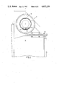
FIG. 1 shows: an embodiment of the device according to the invention in side elevation,
FIG. 2 shows: the device in cross-section taken on the line II--II in FIG. 1,
FIG. 3 shows: an elevation of the device taken on the arrow III in FIG. 2, partly broken away,
FIG. 4 shows a part of the device shown in FIG. 3 on an enlarged scale,
FIG. 5 shows on an enlarged scale a part of the device shown in FIG. 1,
FIG. 6 shows also on an enlarged scale the wind-up mechanism in cross-section,
FIGS. 7a, 7b, 7c and 7d show diagrammatically the feeding slide in successive positions,
FIG. 8 is a side elevation, partly broken away, of another embodiment of the device according to the invention.
Des. of the preferred Embodiments
The device 1 shown in FIGS. 1 to 3 comprises a housing 3 which acts as a basic element and as a support and on which are secured a reel holder 5, a guide 7 for a tape T with electronic components, an ejection mechanism 9 and a wind-up mechanism 11; a feeding and locking mechanism in the form of a sliding mechanism 13 is slidably journalled in a cavity 14 in the housing 3. The said mechanisms are united with the housing to a cassette unit. The device serves for feeding electronic components packed in the tape T to a pick-up position P; the device 1 is coupled for this purpose to another device, such as a component mounting device, which serves for further processing the components supplied in the pick-up position P; the two devices are positioned with respect to each other so that the center line of the ejection mechanism 9 coincides with a center line of a pick-up not shown, which forms part of the component mounting device. The housing 3 is provided on the upper side and on the lower side with reference surfaces on which profiles 15a and 17 are provided, which serve for positioning the cassette unit with respect to the said component mounting device. The reel holder 5 is pivotally arranged on a pivot pin 19, which is secured to the profile 17. Reference numeral 21 denotes a reel shaft which is secured on the reel holder 5 and on which a reel 23 can be journalled. The sliding mechanism 13 mainly consists of a driving slide 25 and a feeding slide 26. The driving slide 25 is displaceable in vertical direction and is driven in a reciprocating movement by means of a lever or a drive roller 27, which co-operates with a slot 29 in the slide. The driving slide 25 is provided with two identical detachable cam plates 31 each provided with a cam track 33 co-operating with fixed cam rollers 35 which act as cam followers and which are secured on the inner wall of the housing 3. By means of a spring 37 and via a clamping block 39, the driving slide 25 is pressed against two guides 41 on the feeding slide 26. The vertical reciprocating driving movement of the driving slide 25 is converted by means of the cam system consisting of the exchangeable cam plates 31 and cam rollers 35 into a horizontal reciprocating feeding movement of the feeding slide 26, which also performs a short reciprocating movement in vertical direction; this vertical stroke of the feeding slide 26 is limited by a slot 43 in the feeding slide co-operating with a fixed cam roller 44. Reference numeral 46 designates a locking lever. The operation of the slides will be described more fully hereinafter.
The guide 7 is provided with a transport channel 8 for feeding and guiding the tape T. The feeding slide 26 has secured on it an abutment arm 51 which co-operates with a driving roller 52 of the wind-up mechanism 11, which serves for pulling off and winding up a cover foil F which closes the cavities in the tape T accommodating the electronic components. The ejection mechanism 9 is also mounted on a reference surface of the housing 3. The ejection mechanism 9 is driven by means of a driving rod 54. The driving rod 54 and the driving roller 27 are preferably coupled to the same drive; at any rate, the driving rod 54 and the driving roller are driven synchronously. The housing 3 is closed on one side by a plate-shaped cover 4.
FIG. 4 shows on an enlarged scale the part of the device comprising the ejection mechanism 9, which mainly consists of a cylindrical housing 55 in which a piston 56 is displaceable, which is connected to a driving pin 57 and is coupled to an ejection pin 58. Reference numeral 59 designates a reset spring. The housing 55 is provided with a mounting part 60 by means of which the ejection mechanism 9 is secured on the housing 3 and is positioned with respect to the housing so that the center line of the ejection pin 58 passes through the center of an opening which is provided in the bottom of the tape T at the center of each cavity. The tape T is aligned in this position in a manner to be described more fully hereinafter by a locking pin 62 which is secured on the locking lever 46. The lever 46 is pivotally journalled on a pivot shaft 63 which is fixedly connected to the housing. Further, the locking lever 46 is provided with a cam roller 64 which co-operates with a groove 65 in the feeding slide 26. Reference numeral 67 denotes a feeding pin which is secured on the feeding slide 26.
FIG. 5 further shows a guide element 69 which serves to guide the cover foil F to the wind-up mechanism 11.
FIG. 6 shows on an enlarged scale a sectional view of the wind-up mechanism 11 which is mounted in a cavity 12 of the housing 3. The aforementioned driving roller 52 which is driven in a reciprocating movement by the abutment arm 51 on the feeding slide 26, is connected via an arcuate opening 53 in the wall of housing 3 to a driving disk 71. By means of friction plates 72, the driving disk 71 co-operates with a driven wheel 73 which is provided with a feeding pawl 74 which co-operates with a pawl toothing 75 at the inner periphery of a reel rim 76. These rotating parts of the wind-up mechanism are covered by a non-rotating cover plate 77, which is fixedly connected to the housing 3 and which is provided with a latch pawl 78, which also co-operates with the pawl toothing 75. A reel flange 79 is connected by means of a bayonet joint 80 to the reel rim 76 and constitutes the exchange part of the reel and of the wind-up mechanism. Via the driving roller 52, the driving disk 71 is set into an oscillating movement and drives via the friction plates 72 the wheel 73. By means of the feeding pawl 74 and the pawl toothing 75, the reel rim 76 is rotated step by step and is held after each step in the new position by the latch pawl 78. By the stepwise rotation of the reel rim 76, the covering foil F is pulled off the tape T, is guided via the guide element 69 to the reel 76, 79 and is wound up. The maximum torque to be transmitted via the friction plates 72 to the reel rim is adjusted by means of an adjustment nut 70 in such a manner that with an increasing diameter of the reel filling the coupling begins to slip in order to avoid that the covering foil F is torn.
FIGS. 7a, 7b, 7c and 7d show the positions of the feeding pin 67 and the locking pin 62 at successive stages of a cycle. For the sake of clarity, the tape T is shown diagrammatically in plan view with the cavities A, B, C and D and with the sprocket holes a, b, c, d, and e which are located at a pitch R, in practice of 4 mm: the cavities in the tape T are each provided with a central opening O, whose center is located in line with the accurately positioned ejection pin 58. The distance between successive components corresponds to the pitch S between two successive openings O which is a multiple of pitch R. The feeding stroke to be performed by the feeding slide is equal to the pitch S. Because the pivot shaft 63 of the locking lever 46 is fixedly secured to the housing, the pivot shaft 63, the locking pin 62 and the ejection pin 58 are accurately positioned with respect to each other. The center line H--H of the ejection pin 58 is taken as reference.
FIG. 7a shows the situation after the feeding stroke has been performed, the relevant component E has been removed from the cavity A and the backward stroke of the feeding slide 26 has started. The tape T is indexed with respect to the ejection pin 58 due to the fact that the locking pin 62 has come into engagement with the sprocket hole a as a result of a rotary movement of the lever 46 about the pivot shaft 63; the rotary movement of the lever 46 takes place due to the fact that during a small initial downward movement of the feeding slide 26 the roller 64 on the lever 46 co-operates with the groove 65 in the feeding slide 26. The feeding slide 26 is taken along by frictional force in the downward movement of the driving slide until the slot 43 in the feeding slide engages by the upper side the fixed cam roller 44. In the situation shown, the cavities B, C and D are still closed by the cover foil F.
FIG. 7b shows the situation in which the feeding slide 26 performs a backward stroke in horizontal direction after the short downward stroke shown in FIG. 7a and as a result of the further downward movement of the driving slide 25. The tape T remains indexed in the same position with the locking pin 62 still in engagement with the same sprocket hole a.
FIG. 7c shows the situation at the beginning of the driving stroke by the driving slide which takes along the feeding slide 26 in a short upward stroke unitl the cam roller 44 comes into engagement with the lower side of the slot 43; as a result of this movement of the feeding slide 26 the lever 46 rotates counter-clockwise about the pivot shaft 63 and the locking pin 62 is disengaged from the sprocket hole a; however, in the meantime the feeding pin 67 has come into engagement with the sprocket hole 3 so that the tape T remains under control.
FIG. 7d finally shows the situation towards the end of the feeding storke. The tape T is transported further by the feeding pin 67 over a feeding distance equal to the pitch S between the two successive openings O, in the embodiment shown equal to thrice the pitch R between the sprocket holes. The cavity B is now located with the opening O in line with the center line H--H of the ejection pin 58. In this situation, the tape T is indexed by the feeding pin 67. The feeding slide 26 has reached the point of reversal and stops for a short time; the locking lever 46 also stops. During the feeding stroke, also the covering foil F is pulled so far off the tape T that the cavity B is open and the component E located therein is accessible. In this situation, the component is removed from the cavity.
As soon as the feeding slide 26 taken along by the driving slide starts again the short downward stroke, the locking lever 46 is rotated clockwise so that the locking pin 62 comes into engagement with the sprocket hole d, while the feeding pin 67 is disengaged from the sprocket hole 3. The situation shown in FIG. 7a is reached again, in which the tape T with the cavity B is located above the ejection pin 58. In this situation component E can be picked-up from cavity B.
The various components are constructed, proportioned, mutually adapted and synchronized with each other in such a manner that the tape T always remains under control, that is to say that either the locking pin 62 or the feeding pin 67 is in engagement with one of the sprocket holes. For these reasons, the two pins never come into engagement with the same transport hole. During the transfer of the tape indexing from one pin to the other, overlap always occurs, the two pins then being simultaneously in engagement with a sprocket hole. The movements of the mechanical elements are adjusted in such a manner that no transport of the tape takes place when a cavity with a component present therein is open.
An alternative embodiment of the device according to the invention is shown in FIG. 8, in which elements comparable with those of the first embodiment are designated by the same reference numerals. The device 81 shown comprises also a housing 3 provided with a guide 7 for feeding a tape with electronic components from a reel 23 journalled on a reel shaft 21 in the housing. There are further secured on the housing 3 an ejection mechanism 9, a wind-up mechanism 11 and a lever 46 with a locking pin 62. The housing accommodates a sliding mechanism 13 consisting of a driving slide 25 and a feeding slide 26 with a feeding pin 67. The driving slide 25 is provided with two identical cam plates 31 each co-operating via a cam track 82 with a fixed cam roller 35. In this embodiment, the abutment arm 51 cooperating with a driving roller 52 for driving the wind-up mechamism 11 is secured on the driving slide 25. The feeding slide is provided with a slot 43 co-operating with a cam roller 44 on the housing for limiting the vertical stroke of the feeding slide. Further, the feeding slide is provided with two guides 41 for the driving slide and with a guide roller 83. Three further guide rollers 85 are also journalled in the housing 3. An elongate spring 87, one end of which is connected to the housing 3 via a pin 88 and the other end of which is secured via a pin 89 on the abutment arm 51, is passed over the guide rollers 83 and 85 in such a manner that the feeding slide 26 with the guides 41 is pressed against the driving slide and the driving slide is pressed with the cams 82 against the cam rollers 35. In this embodiment, the driving slide 25 is driven only in the forward upward stroke against the action of the spring 87; the backward stroke of the driving slide 25 takes place under the action of the spring 87. In the embodiment shown, the wind-up mechanism 11 is driven by the abutment arm 51 upon the backward stroke of the driving slide 25, against the action of a spring not shown.
Product tapes, which have the same width, it is true, but in which the electronic components are enclosed at different pitches, require a different feeding stroke. A minimum readjustment is required for such an adaptation of the cassette unit according to the invention. Only the cam plates 31 have to be exchanged for cam plates which convert the driving stroke of the driving slide 25 into the desired feeding s troke of the feeding slide 26. The sliding mechanism 13 is readily accessible by simply removing the cover 4. If the cam plates 31 are integral with the driving slide 25, the whole driving slide is exchanged.
A further readjustment is required for the adaptation of the cassette unit to product tapes with varous tape widths; the guiding profiles 15 and 17, the ejection mechanism 9 as a whole, the guide 7 for the tape and the exchangeable reel flange 79 of the wind-up mechanism 11 have to be exchanged.
As already set out above, a number of standard tapes with standard dimensions have been developed for packing electronic chiptype components; the pitch of the sprocket holes is 4 mm; the distance between successive components and hence the required feeding stroke is equal to a multiple of 4 mm: the widths of the packing tape increases from 8 mm via a sequence of 12, 16 and 24 mm to 32 mm. Taking the said standard dimensions into account, the stock of mechanical elements can remain limited, especially if extreme dimensions which are hardly usual are left out of consideration, at least by the user.
The flexibility of the cassette unit according to the invention has been clearly demonstrated. An element which intentionally is not integrated in the cassette is a cutting device for cutting the empty tape into pieces. Since such a cutting device does not require an accurate arrangement and positioning, it seems recommendable not to combine the cutting device with the precision cassette according to the invention.
In the embodiment described the components are supplied in a tape, the cavities of which each are provided with a central opening; as in this case the ejection pin 58 has not to perforate the bottom of the cavities, the free end of the ejection pin is blunt and is provided with an end face. However the components may also be supplied in a tape which is devoid of orifices in the bottom of the cavities; as in this case the ejection pin 58 has to perforate the bottom of the cavities, the free end of the ejection pin 58 is pointed.
The different parts of the cassette unit may be made in any convenient material like metal, especially light metal alloy or synthetic resin; the parts may be manufactured by the most economic proces, like injection moulding.

Claims (8)

What is claimed is:
1. A device for feeding electronic components packed in a tape to a pick-up position, said device being an exchangeable cassette and comprising:
(a) a supply reel for said tape,
(b) a holder for said supply reel,
(c) a feeding mechanism provided with a feeding pin and coupled to said supply reel for moving said components to said pick-up position,
(d) a locking mechanism provided with a locking pin coupled to said supply reel for preventing undesired rotation of said tape,
(e) an ejection mechanism provided with an injection pin and coupled to said feeding mechanism for ejecting components from said tape at said pick-up position,
(f) a wind-up mechanism coupled to said supply reel for guiding said tape along a path coinciding with said pick-up position,
(g) sliding mechanism coupled to said feeding mechanism and said wind-up mechanism for driving said feeding and said wind-up mechanism,
(h) and a housing secured to and providing a common support for said holder, and said mechanism and supplied with a support for said supply reel, a transport channel constituting a guide for said tape with said components to said pick-up position and a bearing for a take-up reel.
2. A device as claimed in claim 1, characterized in that the sliding mechanism comprises a feeding slide and a driving slide, which slides, viewed in the feeding direction, are positively coupled to each other by a shape connection and, viewed in a direction transverse to the feeding direction, are frictionally coupled to each other by a force connection, the feeding pin being secured on the feeding slide and the locking pin being secured on a lever rotatable about a fixed pivot shaft and co-operating with the feeding slide, while the driving slide co-operates with a cam system operative in the feeding direction and consisting of cam tracks and cam followers.
3. A device as claimed in claim 2, characterized in that the cam tracks are provided on exchangeable cam plates.
4. A device as claimed in claim 2 or 3, characterized in that the feeding slide is provided with guides co-operating with the driving slide, the driving slide and the guides being pressed against each other by a spring.
5. A device as claimed in claim 4, characterized in that the driving slide is displaced during the forward stroke against the action of the spring, the backward stroke taking place under the action of the spring, the spring simultaneously pressing the cam tracks and the cam followers against each other.
6. A device as claimed in claim 1, characterized in that the sliding mechanism is provided with an abutment arm which co-operates with a driving pin for driving the wind-up mechanism.
7. A device as claimed in claim 6, characterized in that the wind-up mechanism mainly comprises a driving disk on which the driving pin is secured, a friction coupling, a driven disk, a reel rim, a detachable reel flange and a cover plate connected to the housing, a feeding pawl being provided on the driven disk and a locking pawl being provided on the cover plate, which pawls co-operate with a pawl toothing at the inner periphery of the reel rim.
8. A device as claimed in claim 1, characterized in that the reel holder is pivotally secured on the housing.
US06/630,563 1983-05-11 1984-07-13 Device for feeding electronic components packed in tape to a pick-up position Expired - Fee Related US4657158A (en)

Applications Claiming Priority (2)

Application Number Priority Date Filing Date Title
NL8303816A NL8303816A (en) 1983-11-05 1983-11-05 APPARATUS FOR SUPPLYING BELT-PACKED ELECTRONIC COMPONENTS TO A RECORDING POSITION.
NL8303816 1983-11-05

Publications (1)

Publication Number Publication Date
US4657158A true US4657158A (en) 1987-04-14

Family

ID=19842666

Family Applications (1)

Application Number Title Priority Date Filing Date
US06/630,563 Expired - Fee Related US4657158A (en) 1983-05-11 1984-07-13 Device for feeding electronic components packed in tape to a pick-up position

Country Status (8)

Country Link
US (1) US4657158A (en)
EP (1) EP0146154B1 (en)
JP (2) JPS60115300A (en)
KR (1) KR910005980B1 (en)
AT (1) ATE32293T1 (en)
DE (1) DE3469124D1 (en)
ES (1) ES8601633A1 (en)
NL (1) NL8303816A (en)

Cited By (26)

* Cited by examiner, † Cited by third party
Publication number Priority date Publication date Assignee Title
US4801044A (en) * 1986-05-27 1989-01-31 Nitto Kogyo Kabushiki Kaisha Chip separation and alignment apparatus
US4923089A (en) * 1987-01-19 1990-05-08 Sanyo Electric Co., Ltd. Parts feed apparatus
US4996680A (en) * 1988-06-03 1991-02-26 Starr Development Company, S.A. Automatic changing apparatus for a recording medium
US5020959A (en) * 1989-04-14 1991-06-04 Universal Instruments Corporation Adjustable shutter for containment of electrical components in tape feeders
US5062543A (en) * 1989-04-14 1991-11-05 Carrar Food pellet dispensing appliance
US5136562A (en) * 1989-04-11 1992-08-04 Staar Development, S.A. Automatic changer for information storage devices
US5134912A (en) * 1990-09-27 1992-08-04 Microelectronics And Computer Technology Corporation Tab tape singulation apparatus and method
US5588614A (en) * 1994-07-07 1996-12-31 Fuji Machine Mfg. Co., Ltd. Electronic-component supplying cartridge
US5590645A (en) * 1990-03-02 1997-01-07 Glaxo Group Limited Inhalation device
US5941674A (en) * 1996-06-12 1999-08-24 Tempo G Interchangeable electronic carrier tape feeder adaptable to various surface mount assembly machines
US6082603A (en) * 1998-06-24 2000-07-04 Fuji Machine Mfg. Co., Ltd. Electric-component tape feeding apparatus and electric-component supplying method
US6202913B1 (en) 1998-06-24 2001-03-20 Fuji Machine Mfg. Co., Ltd. Electric-component supplying unit
US6338192B1 (en) * 1998-09-25 2002-01-15 Matsushita Electric Industrial Co., Ltd. Component mounting machine and safety device thereof
US6536427B2 (en) 1990-03-02 2003-03-25 Glaxo Group Limited Inhalation device
US6792945B2 (en) 1990-03-02 2004-09-21 Glaxo Group Limited Inhalation device
US20040250812A1 (en) * 1990-03-02 2004-12-16 Davies Michael Birsha Inhalation device
EP1786254A1 (en) * 2005-11-14 2007-05-16 LCM S.r.l Linear multiple feeder for automatic SMD electronic components positioning apparatuses
US20110162202A1 (en) * 2008-09-04 2011-07-07 Panasonic Corporation Electronic component mounting device and work method of electronic component mounting device
US20130153619A1 (en) * 2010-10-14 2013-06-20 Panasonic Corporation Tape feeder and method of mounting tape onto tape feeder
US20130161370A1 (en) * 2010-10-14 2013-06-27 Panasonic Corporation Tape feeder and method of mounting tape onto tape feeder
US20130161371A1 (en) * 2010-10-14 2013-06-27 Panasonic Corporation Tape feeder and method of mounting tape onto tape feeder
US20160212900A1 (en) * 2013-10-09 2016-07-21 Fuji Machine Mfg. Co., Ltd Installation position optimization program
US20170049014A1 (en) * 2011-04-08 2017-02-16 Mycronic AB Tape feeder and method for moving a carrier tape towards a picking position in a component mounting machine
US20180270998A1 (en) * 2014-12-03 2018-09-20 Fuji Machine Mfg. Co., Ltd. Tape feeder
US11039560B2 (en) * 2017-10-16 2021-06-15 Panasonic Intellectual Property Management Co., Ltd. Working machine, storing-target-body supply device, and method for manufacturing workpiece having storing-target body installed thereon
US20240064948A1 (en) * 2021-01-21 2024-02-22 Panasonic Intellectual Property Management Co., Ltd. Housing device

Families Citing this family (7)

* Cited by examiner, † Cited by third party
Publication number Priority date Publication date Assignee Title
US4586670A (en) * 1984-12-17 1986-05-06 Usm Corporation Tape stripper for electrical component tape feeder
DE8518982U1 (en) * 1985-06-29 1986-01-16 Simprop electronic Walter Claas GmbH & Co, 4834 Harsewinkel Components dispenser
JPS62144255U (en) * 1986-02-28 1987-09-11
JPH0751836Y2 (en) * 1992-11-02 1995-11-22 株式会社鈴木 Tape winding device
JP3706210B2 (en) * 1996-02-07 2005-10-12 ヤマハ発動機株式会社 Automatic parts feeder
DE102008018428A1 (en) * 2007-04-14 2008-10-23 Böllhoff Verbindungstechnik GmbH Setting tool, method and apparatus for feeding fasteners
US8192160B2 (en) 2010-09-01 2012-06-05 General Electric Company Wind turbine having variable height and method for operating the same

Citations (4)

* Cited by examiner, † Cited by third party
Publication number Priority date Publication date Assignee Title
US2979726A (en) * 1956-05-01 1961-04-18 Sylvania Electric Prod Electronic component assembly apparatus
US3090521A (en) * 1958-12-05 1963-05-21 Pneumafil Corp Vending means
US4337864A (en) * 1980-02-22 1982-07-06 Docutel Corporation Currency note dispensing system
US4410103A (en) * 1980-03-10 1983-10-18 Furma Manufacturing Co. Pty. Ltd. Sequential unit feeding apparatus

Family Cites Families (6)

* Cited by examiner, † Cited by third party
Publication number Priority date Publication date Assignee Title
US3000529A (en) * 1958-10-27 1961-09-19 United Shoe Machinery Corp Element applying machines
US3263467A (en) * 1963-03-20 1966-08-02 Warwick Electronics Inc Component inserting head
JPS55118698A (en) * 1979-03-05 1980-09-11 Matsushita Electric Industrial Co Ltd Device for mounting electronic part
JPS56132000A (en) * 1980-03-19 1981-10-15 Hitachi Ltd Assembling part supplying device
NL8103574A (en) * 1981-07-29 1983-02-16 Philips Nv METHOD AND APPARATUS FOR PLACING ELECTRICAL AND / OR ELECTRONIC COMPONENTS ON A SUBSTRATE.
NL8103573A (en) * 1981-07-29 1983-02-16 Philips Nv DEVICE FOR AT THE SAME TIME FEEDING MULTIPLE ELECTRICAL AND / OR ELECTRONIC COMPONENTS IN TIRES AT A PARTICULAR POSITION.

Patent Citations (4)

* Cited by examiner, † Cited by third party
Publication number Priority date Publication date Assignee Title
US2979726A (en) * 1956-05-01 1961-04-18 Sylvania Electric Prod Electronic component assembly apparatus
US3090521A (en) * 1958-12-05 1963-05-21 Pneumafil Corp Vending means
US4337864A (en) * 1980-02-22 1982-07-06 Docutel Corporation Currency note dispensing system
US4410103A (en) * 1980-03-10 1983-10-18 Furma Manufacturing Co. Pty. Ltd. Sequential unit feeding apparatus

Cited By (44)

* Cited by examiner, † Cited by third party
Publication number Priority date Publication date Assignee Title
US4801044A (en) * 1986-05-27 1989-01-31 Nitto Kogyo Kabushiki Kaisha Chip separation and alignment apparatus
US4923089A (en) * 1987-01-19 1990-05-08 Sanyo Electric Co., Ltd. Parts feed apparatus
US4996680A (en) * 1988-06-03 1991-02-26 Starr Development Company, S.A. Automatic changing apparatus for a recording medium
US5136562A (en) * 1989-04-11 1992-08-04 Staar Development, S.A. Automatic changer for information storage devices
US5020959A (en) * 1989-04-14 1991-06-04 Universal Instruments Corporation Adjustable shutter for containment of electrical components in tape feeders
US5062543A (en) * 1989-04-14 1991-11-05 Carrar Food pellet dispensing appliance
US5873360A (en) * 1990-03-02 1999-02-23 Glaxo Group Limited Inhalation device
US7389775B2 (en) 1990-03-02 2008-06-24 Glaxo Group Limited Inhalation device
US5590645A (en) * 1990-03-02 1997-01-07 Glaxo Group Limited Inhalation device
US5860419A (en) * 1990-03-02 1999-01-19 Glaxo Group Limited Inhalation device
US20040250812A1 (en) * 1990-03-02 2004-12-16 Davies Michael Birsha Inhalation device
US6792945B2 (en) 1990-03-02 2004-09-21 Glaxo Group Limited Inhalation device
US6032666A (en) * 1990-03-02 2000-03-07 Glaxo Group Limited Inhalation device
US6536427B2 (en) 1990-03-02 2003-03-25 Glaxo Group Limited Inhalation device
US7225808B2 (en) 1990-03-02 2007-06-05 Glaxo Group Limited Inhalation device
US20070107724A9 (en) * 1990-03-02 2007-05-17 Davies Michael B Inhalation device
US20060107948A9 (en) * 1990-03-02 2006-05-25 Davies Michael B Inhalation device
US20050126568A1 (en) * 1990-03-02 2005-06-16 Davies Michael B. Inhalation device
US5134912A (en) * 1990-09-27 1992-08-04 Microelectronics And Computer Technology Corporation Tab tape singulation apparatus and method
US5588614A (en) * 1994-07-07 1996-12-31 Fuji Machine Mfg. Co., Ltd. Electronic-component supplying cartridge
US5941674A (en) * 1996-06-12 1999-08-24 Tempo G Interchangeable electronic carrier tape feeder adaptable to various surface mount assembly machines
US6139246A (en) * 1996-06-12 2000-10-31 Tempo G Interchangeable electronic carrier tape feeder adaptable to various surface mount assembly machines
US6202913B1 (en) 1998-06-24 2001-03-20 Fuji Machine Mfg. Co., Ltd. Electric-component supplying unit
US6082603A (en) * 1998-06-24 2000-07-04 Fuji Machine Mfg. Co., Ltd. Electric-component tape feeding apparatus and electric-component supplying method
US6490781B2 (en) 1998-09-25 2002-12-10 Matsushita Electric Industrial Co., Ltd. Component mounting machine and safety device thereof
US6338192B1 (en) * 1998-09-25 2002-01-15 Matsushita Electric Industrial Co., Ltd. Component mounting machine and safety device thereof
EP1786254A1 (en) * 2005-11-14 2007-05-16 LCM S.r.l Linear multiple feeder for automatic SMD electronic components positioning apparatuses
US20070169436A1 (en) * 2005-11-14 2007-07-26 Lcm S.R.L. Linear multiple feeder for automatic surface-mounting device positioning apparatuses
US7681617B2 (en) 2005-11-14 2010-03-23 Lcm S.R.L. Linear multiple feeder for automatic surface-mounting device positioning apparatuses
US20110162202A1 (en) * 2008-09-04 2011-07-07 Panasonic Corporation Electronic component mounting device and work method of electronic component mounting device
US9084385B2 (en) * 2008-09-04 2015-07-14 Panasonic Intellectual Property Management Co., Ltd. Electronic component mounting device and work method of electronic component mounting device
US20130161370A1 (en) * 2010-10-14 2013-06-27 Panasonic Corporation Tape feeder and method of mounting tape onto tape feeder
US20130161371A1 (en) * 2010-10-14 2013-06-27 Panasonic Corporation Tape feeder and method of mounting tape onto tape feeder
US8955730B2 (en) * 2010-10-14 2015-02-17 Panasonic Corporation Tape feeder and method of mounting tape onto tape feeder
US20130153619A1 (en) * 2010-10-14 2013-06-20 Panasonic Corporation Tape feeder and method of mounting tape onto tape feeder
US20170049014A1 (en) * 2011-04-08 2017-02-16 Mycronic AB Tape feeder and method for moving a carrier tape towards a picking position in a component mounting machine
US9901019B2 (en) * 2011-04-08 2018-02-20 Mycronic AB Tape feeder and method for moving a carrier tape towards a picking position in a component mounting machine
US20160212900A1 (en) * 2013-10-09 2016-07-21 Fuji Machine Mfg. Co., Ltd Installation position optimization program
US10130020B2 (en) * 2013-10-09 2018-11-13 Fuji Corporation Installation position optimization program
US20180270998A1 (en) * 2014-12-03 2018-09-20 Fuji Machine Mfg. Co., Ltd. Tape feeder
US10602648B2 (en) * 2014-12-03 2020-03-24 Fuji Corporation Tape feeder
US11039560B2 (en) * 2017-10-16 2021-06-15 Panasonic Intellectual Property Management Co., Ltd. Working machine, storing-target-body supply device, and method for manufacturing workpiece having storing-target body installed thereon
US20240064948A1 (en) * 2021-01-21 2024-02-22 Panasonic Intellectual Property Management Co., Ltd. Housing device
US12439574B2 (en) * 2021-01-21 2025-10-07 Panasonic Intellectual Property Management Co., Ltd. Housing device

Also Published As

Publication number Publication date
ES537328A0 (en) 1985-10-16
NL8303816A (en) 1985-06-03
EP0146154B1 (en) 1988-01-27
KR910005980B1 (en) 1991-08-09
ATE32293T1 (en) 1988-02-15
JPS60115300A (en) 1985-06-21
EP0146154A1 (en) 1985-06-26
DE3469124D1 (en) 1988-03-03
JPH08631U (en) 1996-04-12
JP2529100Y2 (en) 1997-03-12
ES8601633A1 (en) 1985-10-16
KR850003833A (en) 1985-06-26

Similar Documents

Publication Publication Date Title
US4657158A (en) Device for feeding electronic components packed in tape to a pick-up position
US4809099A (en) Transport for tape cartridge with leader block
US4887778A (en) Feeder drive assembly and replaceable section for tape supplying and cover peeling
AU3348989A (en) Automatic magnetic tape cartridge stack loader for tape drive systems
GB1461343A (en) Automatic film-cassette fabrication
US4240120A (en) Cassette-to-cassette duplicator
GB2103820A (en) Tape splicing
US4040108A (en) Magnetic sheet reader
JPS6133923A (en) Fixture for connecting piece
WO1986005004A1 (en) An automatic printing machine for printing text on cinematographic film
WO2000030090A1 (en) Recording and/or reproducing device having drive means for the actuation of holder means for a cassette and of retaining means for a tape pull-out element
US4343837A (en) Tipper for embossed cards and removable cassette for use therewith
GB1202256A (en) Tape roll handling apparatus
ES360702A1 (en) Loading apparatus for cartridge for strip material
GB1146382A (en) Pinch roller actuating mechanism
JPH07101792B2 (en) Electronic component supply device and reel holder setting method for the device
US4763214A (en) Head drive mechanism for electronic still camera
GB1140077A (en) Tape recorder
US2480061A (en) Method for manufacturing slide fasteners
US3756590A (en) Card feeding devices
GB1274332A (en) Electric part mounting apparatus
US3768135A (en) Assembly apparatus
EP0212279A1 (en) Magnetic-recording apparatus
DE2462650C2 (en) Cassette adapter for micro cassettes
DE2837865A1 (en) TAPE DRIVE FOR A MAGNETOPHONE, IN PARTICULAR FOR A TAPE OR VIDEO TAPE

Legal Events

Date Code Title Description
AS Assignment

Owner name: U.S. PHILIPS CORPORATION 100 EAST 42ND ST., NEW YO

Free format text: ASSIGNMENT OF ASSIGNORS INTEREST.;ASSIGNORS:THEELEN, HUBERTUS J.;VERBERNE, PETRUS A. C.;REEL/FRAME:004375/0472;SIGNING DATES FROM 19841123 TO 19841129

AS Assignment

Owner name: U.S. PHILIPS CORPORATION 100 EAST 42ND ST., NEW YO

Free format text: ASSIGNMENT OF ASSIGNORS INTEREST.;ASSIGNORS:FAES, FRANCISCUS C. M.;VAN GASTEL, JOSEPHUS M. M.;SMOLDERS, JOZEF G. H. M.;REEL/FRAME:004375/0471;SIGNING DATES FROM 19841123 TO 19850118

FPAY Fee payment

Year of fee payment: 4

FPAY Fee payment

Year of fee payment: 8

REMI Maintenance fee reminder mailed
LAPS Lapse for failure to pay maintenance fees
FP Lapsed due to failure to pay maintenance fee

Effective date: 19990414

STCH Information on status: patent discontinuation

Free format text: PATENT EXPIRED DUE TO NONPAYMENT OF MAINTENANCE FEES UNDER 37 CFR 1.362