US4645344A - Optical device for an emission spectrometer - Google Patents
Optical device for an emission spectrometer Download PDFInfo
- Publication number
- US4645344A US4645344A US06/759,927 US75992785A US4645344A US 4645344 A US4645344 A US 4645344A US 75992785 A US75992785 A US 75992785A US 4645344 A US4645344 A US 4645344A
- Authority
- US
- United States
- Prior art keywords
- frame
- ribbon
- slit
- bar means
- polychromatic light
- Prior art date
- Legal status (The legal status is an assumption and is not a legal conclusion. Google has not performed a legal analysis and makes no representation as to the accuracy of the status listed.)
- Expired - Lifetime
Links
- 230000003287 optical effect Effects 0.000 title claims abstract description 8
- 239000002184 metal Substances 0.000 claims abstract description 7
- 229910052751 metal Inorganic materials 0.000 claims abstract description 7
- PXHVJJICTQNCMI-UHFFFAOYSA-N Nickel Chemical compound [Ni] PXHVJJICTQNCMI-UHFFFAOYSA-N 0.000 claims description 4
- 229910052759 nickel Inorganic materials 0.000 claims description 2
- 230000004907 flux Effects 0.000 abstract description 3
- 230000001105 regulatory effect Effects 0.000 description 5
- 230000010339 dilation Effects 0.000 description 1
- 238000004070 electrodeposition Methods 0.000 description 1
- 230000005284 excitation Effects 0.000 description 1
- 238000004519 manufacturing process Methods 0.000 description 1
- 238000001228 spectrum Methods 0.000 description 1
Images
Classifications
-
- G—PHYSICS
- G01—MEASURING; TESTING
- G01J—MEASUREMENT OF INTENSITY, VELOCITY, SPECTRAL CONTENT, POLARISATION, PHASE OR PULSE CHARACTERISTICS OF INFRARED, VISIBLE OR ULTRAVIOLET LIGHT; COLORIMETRY; RADIATION PYROMETRY
- G01J3/00—Spectrometry; Spectrophotometry; Monochromators; Measuring colours
- G01J3/02—Details
- G01J3/04—Slit arrangements slit adjustment
-
- G—PHYSICS
- G01—MEASURING; TESTING
- G01J—MEASUREMENT OF INTENSITY, VELOCITY, SPECTRAL CONTENT, POLARISATION, PHASE OR PULSE CHARACTERISTICS OF INFRARED, VISIBLE OR ULTRAVIOLET LIGHT; COLORIMETRY; RADIATION PYROMETRY
- G01J3/00—Spectrometry; Spectrophotometry; Monochromators; Measuring colours
- G01J3/12—Generating the spectrum; Monochromators
- G01J3/18—Generating the spectrum; Monochromators using diffraction elements, e.g. grating
- G01J3/20—Rowland circle spectrometers
-
- G—PHYSICS
- G01—MEASURING; TESTING
- G01J—MEASUREMENT OF INTENSITY, VELOCITY, SPECTRAL CONTENT, POLARISATION, PHASE OR PULSE CHARACTERISTICS OF INFRARED, VISIBLE OR ULTRAVIOLET LIGHT; COLORIMETRY; RADIATION PYROMETRY
- G01J3/00—Spectrometry; Spectrophotometry; Monochromators; Measuring colours
- G01J3/28—Investigating the spectrum
- G01J3/443—Emission spectrometry
Definitions
- the present invention relates to an optical device having a Paschen-Runge mounting arrangement, suitable for splitting up polychromatic light emitted when the sample to be analyzed is being excited.
- This optical device is intended to be mounted in a direct reading emission spectrometer.
- An optical device having a Paschen-Runge mounting arrangement comprises a concave diffraction grating which receives through an inlet slit the polychromatic light emitted by the excitation of the sample to be analyzed.
- the inlet slit is placed onto the Rowland circle which is tangential to the concave spherical surface on which the grating is formed and which has a diameter equal to the radius of curvature of that surface.
- the monochromatic bundles, supplied by the grating converge in points situated on the Rowland circle.
- the chosen wavelengths are selected by the outlet slits placed on the Rowland circle.
- the slits, placed on the Rowland circle are generally mounted individually onto a rigid slit-carrier which can be regulated, relative to the frame. This fitting is not well adapted for regulating the outlet slits.
- the subject of the present invention is an optical device for a spectrometer, using the Paschen-Runge mounting arrangement, in which regulation of the slit-carrier can be easily brought about.
- the device comprises, on a frame in the shape of a circle sector, an inlet slit illuminated by polychromatic light, a concave diffraction grating which diffracts the bundle of polychromatic light coming from the inlet slit, outlet slits worked into a slit-carrier for selecting the monochromatic bundles coming from the grating and detectors for measuring the light fluxes of the said monochromatic bundles, the inlet slit, the diffraction grating and the outlet slits being placed on the Rowland circle, wherein essentially the slit-carrier consists of a flexible continuous metal ribbon and wherein the cylindrical support bearings, which serve as supports for the slit-carrier, form part of the frame and are situated on either side of an aperture for the passage of monochromatic bundles, the ends of this ribbon being fixed to the frame.
- the ends of the ribbon are fixed by means for regulating its position and its tension.
- the ribbon is made of two parts, connected to each other by a connecting piece.
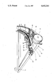
- the single FIGURE is an overall view of the device according to the invention.
- the device comprises a metal frame 1, having a general shape of a circle sector.
- This single-block frame is made up of two branches 11 which form a V and are joined by one or more rails 12, 13, having the shape of circle arcs.
- the device comprises an inlet slit 21 which forms part of a mounting arrangement with a screw regulator 22 which is carried by the frame.
- the inlet slit receives, through the objective 3, the bundle of polychromatic light emitted by the excited sample.
- the bundle passing through the inlet slit is received by a diffraction grating 4, formed on a concave spherical surface.
- This grating is mounted in a support which is fixed to the apex of the V formed by the frame. It splits up the bundle of polychromatic light into several monochromatic bundles, producing images of the inlet slit which are located on the Rowland circle passing through the inlet slit and tangential to the grating, the diameter of this circle being equal to the radius of curvature of the spherical surface carrying the lines of the grating.
- the rail 12 of the frame forms an aperture or window, into which the monochromatic bundles pass.
- this rail forms cylindrical support bearings 122, which are situated on either side of this aperture and which surround a cylinder passing through the Rowland circle.
- the outlet slits 51 are worked into a slit-carrier 5 which covers the whole of the wavelengths selected from the spectrum supplied by the grating.
- This slit-carrier consists of a flexible metal ribbon which is held at its ends so as to be in contact with the cylindrical bearings 122 of the frame which serve for guiding it along the Rowland circle.
- the ends of the slit-carrier ribbon are attached to two bars, held in fixed position by a screw and nut system 35 in a groove 121 of the rail 12.
- Each bar 6 comprises a screw-nut which enables the position of the ribbon 5 to be regulated along the Rowland circle and the tension to be regulated.
- the ribbon is formed by two parts, connected to each other by a connecting piece 7 which acts as a tightener.
- the ribbon is made, by electrodeposition, of nickel, the dilation coefficient of which is close to that of foundry metal or of some other metal, by a suitable manufacturing process.
- the monochromatic bundles After passing through the outlet slits 51, the monochromatic bundles are guided, directly or by way of mirrors, onto detectors 8, consisting of photomultipliers which measure the light fluxes of these bundles.
- detectors 8 are mounted on rails 12 and 13.
Landscapes
- Physics & Mathematics (AREA)
- Spectroscopy & Molecular Physics (AREA)
- General Physics & Mathematics (AREA)
- Spectrometry And Color Measurement (AREA)
- Investigating, Analyzing Materials By Fluorescence Or Luminescence (AREA)
Abstract
An optical device having a Paschen-Runge mounting arrangement, suitable for splitting up the polychromatic light emitted when the sample to be analyzed is being excited, comprising a frame (1) having the shape of a circle sector, an inlet slit (21) illuminated by polychromatic light, a concave diffraction grating (4) which diffracts the bundle of polychromatic light coming from the inlet slit, outlet slits (51) worked into a slit-carrier (5) and selecting the monochromatic bundles coming from the grating, and detectors for measuring the light fluxes of the monochromatic bundles. The slit-carrier (5) consists of a flexible continuous metal ribbon, and the cylindrical support bearings (122), which serve as supports for the slit-carrier, form part of the frame and are situated on either side of an aperture for the passage of monochromatic bundles, the ends of this ribbon being fixed to the frame (1). The device is intended to be mounted in a direct reading emission spectrometer.
Description
This application is a continuation of application Ser. No. 452,477, filed Dec. 23, 1982, abandoned.
The present invention relates to an optical device having a Paschen-Runge mounting arrangement, suitable for splitting up polychromatic light emitted when the sample to be analyzed is being excited. This optical device is intended to be mounted in a direct reading emission spectrometer.
An optical device having a Paschen-Runge mounting arrangement comprises a concave diffraction grating which receives through an inlet slit the polychromatic light emitted by the excitation of the sample to be analyzed. The inlet slit is placed onto the Rowland circle which is tangential to the concave spherical surface on which the grating is formed and which has a diameter equal to the radius of curvature of that surface. The monochromatic bundles, supplied by the grating, converge in points situated on the Rowland circle. The chosen wavelengths are selected by the outlet slits placed on the Rowland circle.
In the Paschen-Runge mounting arrangements, the slits, placed on the Rowland circle, are generally mounted individually onto a rigid slit-carrier which can be regulated, relative to the frame. This fitting is not well adapted for regulating the outlet slits.
The subject of the present invention is an optical device for a spectrometer, using the Paschen-Runge mounting arrangement, in which regulation of the slit-carrier can be easily brought about.
The device according to the invention comprises, on a frame in the shape of a circle sector, an inlet slit illuminated by polychromatic light, a concave diffraction grating which diffracts the bundle of polychromatic light coming from the inlet slit, outlet slits worked into a slit-carrier for selecting the monochromatic bundles coming from the grating and detectors for measuring the light fluxes of the said monochromatic bundles, the inlet slit, the diffraction grating and the outlet slits being placed on the Rowland circle, wherein essentially the slit-carrier consists of a flexible continuous metal ribbon and wherein the cylindrical support bearings, which serve as supports for the slit-carrier, form part of the frame and are situated on either side of an aperture for the passage of monochromatic bundles, the ends of this ribbon being fixed to the frame.
According to one aspect of the invention, the ends of the ribbon are fixed by means for regulating its position and its tension. According to another aspect, the ribbon is made of two parts, connected to each other by a connecting piece.
The invention will now be described in greater detail with reference to an embodiment given by way of example and shown in the attached drawing.
The single FIGURE is an overall view of the device according to the invention.
With reference to the FIGURE, the device comprises a metal frame 1, having a general shape of a circle sector. This single-block frame is made up of two branches 11 which form a V and are joined by one or more rails 12, 13, having the shape of circle arcs.
The device comprises an inlet slit 21 which forms part of a mounting arrangement with a screw regulator 22 which is carried by the frame. The inlet slit receives, through the objective 3, the bundle of polychromatic light emitted by the excited sample.
The bundle passing through the inlet slit is received by a diffraction grating 4, formed on a concave spherical surface. This grating is mounted in a support which is fixed to the apex of the V formed by the frame. It splits up the bundle of polychromatic light into several monochromatic bundles, producing images of the inlet slit which are located on the Rowland circle passing through the inlet slit and tangential to the grating, the diameter of this circle being equal to the radius of curvature of the spherical surface carrying the lines of the grating. The rail 12 of the frame forms an aperture or window, into which the monochromatic bundles pass. Moreover, this rail forms cylindrical support bearings 122, which are situated on either side of this aperture and which surround a cylinder passing through the Rowland circle.
The outlet slits 51 are worked into a slit-carrier 5 which covers the whole of the wavelengths selected from the spectrum supplied by the grating. This slit-carrier consists of a flexible metal ribbon which is held at its ends so as to be in contact with the cylindrical bearings 122 of the frame which serve for guiding it along the Rowland circle. The ends of the slit-carrier ribbon are attached to two bars, held in fixed position by a screw and nut system 35 in a groove 121 of the rail 12. Each bar 6 comprises a screw-nut which enables the position of the ribbon 5 to be regulated along the Rowland circle and the tension to be regulated.
The ribbon is formed by two parts, connected to each other by a connecting piece 7 which acts as a tightener. The ribbon is made, by electrodeposition, of nickel, the dilation coefficient of which is close to that of foundry metal or of some other metal, by a suitable manufacturing process.
After passing through the outlet slits 51, the monochromatic bundles are guided, directly or by way of mirrors, onto detectors 8, consisting of photomultipliers which measure the light fluxes of these bundles. The detectors 8 are mounted on rails 12 and 13.
Claims (5)
1. An optical device having a Paschen-Runge arrangement for an emission spectrometer, comprising a frame, an inlet slit mounted on said frame to be illuminated by a bundle of polychromatic light, a concave diffraction grating mounted on said frame for diffracting a bundle of polychromatic light coming from said inlet slit and producing a number of monochromatic bundles at outlet points, outlet slit means for selecting said monochromatic bundles at said points, said outlet slit means being supported by cylindrical support bearings and two bar means, securing means holding said bar means in position, a flexible two part metal ribbon which defines said outlet slits at said points, said ribbon comprising two ribbon parts each connected, at one end thereof, to its respective bar means, said ribbon parts being connected, at their other ends, to each other by a tightening connection means, said inlet and outlet slits being located on the Rowland circle which is tangential to the diffraction grating.
2. An optical device having a Paschen-Runge arrangement for an emission spectrometer, comprising:
(a) a frame;
(b) an inlet slit mounted on said frame and positioned to receive a bundle of polychromatic light;
(c) a concave diffraction grating mounted on said frame and positioned to receive said bundle of polychromatic light coming from said inlet slit for diffracting said polychromatic light into a number of monchromatic bundles;
(d) support bearings mounted on said frame and defining a support path substantially coincident with the Rowland circle tangent to and defined by said diffraction grating;
(e) first and second bar means including means for mounting said bar means at various points along a path substantially coincident with the path defined by said support bearing;
(f) first and second securing means associated with said first and second bar means, respectively, for securing its respective bar means at various selectable points;
(g) a first flexible ribbon part mounted in said support bearing, one end of said first ribbon part being connected to said first bar means;
(h) a second ribbon part mounted in said support bearing, one end of said second ribbon part being connected to said second bar means; and
(i) tightening connection means for connecting the other end of said second ribbon part to the other end of said first flexible ribbon part, said first and second ribbon parts defining at least one outlet slit.
3. A device as claimed in claim 2, wherein said bar means are held in position by a screw and nut system in a groove defined by said frame.
4. A device as claimed in claim 3, wherein said ribbon parts are made of nickel.
5. A device as in claim 3, further comprising an objective lens mounted on said frame for illuminating said inlet slit with said polychromatic bundle.
Applications Claiming Priority (2)
| Application Number | Priority Date | Filing Date | Title |
|---|---|---|---|
| FR8200062A FR2519426B1 (en) | 1982-01-05 | 1982-01-05 | OPTICAL DEVICE FOR AN EMISSION SPECTROMETER |
| FR8200062 | 1982-01-05 |
Related Parent Applications (1)
| Application Number | Title | Priority Date | Filing Date |
|---|---|---|---|
| US06452477 Continuation | 1982-12-23 |
Publications (1)
| Publication Number | Publication Date |
|---|---|
| US4645344A true US4645344A (en) | 1987-02-24 |
Family
ID=9269718
Family Applications (1)
| Application Number | Title | Priority Date | Filing Date |
|---|---|---|---|
| US06/759,927 Expired - Lifetime US4645344A (en) | 1982-01-05 | 1985-07-26 | Optical device for an emission spectrometer |
Country Status (6)
| Country | Link |
|---|---|
| US (1) | US4645344A (en) |
| EP (1) | EP0083574B1 (en) |
| JP (1) | JPS58120133A (en) |
| AT (1) | ATE21557T1 (en) |
| DE (1) | DE3365360D1 (en) |
| FR (1) | FR2519426B1 (en) |
Cited By (6)
| Publication number | Priority date | Publication date | Assignee | Title |
|---|---|---|---|---|
| WO2002012950A1 (en) * | 2000-08-10 | 2002-02-14 | Yuil Engineering Corp | Method of analyzing spectrum using multi-slit member and multi-channel spectrograph using the same |
| US20070081574A1 (en) * | 2003-10-28 | 2007-04-12 | Hiroshi Kawanaka | Thermal sensor |
| CN100348968C (en) * | 2006-03-10 | 2007-11-14 | 哈尔滨工业大学 | Method for detecting emission spectrum in procedure of material ablation, and detection device |
| US20070291266A1 (en) * | 2006-06-15 | 2007-12-20 | Canon Kabushiki Kaisha | Spectroscope and spectroscopic method |
| US20090284740A1 (en) * | 2004-12-16 | 2009-11-19 | Spectro Analytical Instruments Gmbh & Co. Kg | Spectrometer Optics Comprising Positionable Slots and Method for the Fully Automatic Transmission of Calibrating Adjustments between Spectrometers Equipped with Optics of this Type |
| US9927361B2 (en) | 2013-05-16 | 2018-03-27 | Carl Zeiss Microscopy Gmbh | Devices and methods for spectroscopic analysis |
Families Citing this family (2)
| Publication number | Priority date | Publication date | Assignee | Title |
|---|---|---|---|---|
| FR2651575B1 (en) * | 1989-09-05 | 1993-11-19 | Instruments Sa | SPECTROCOPY ANALYSIS DEVICE. |
| NL8903045A (en) * | 1989-12-12 | 1991-07-01 | Philips Nv | SPECTROMETER WITH SPLIT BOX. |
Citations (2)
| Publication number | Priority date | Publication date | Assignee | Title |
|---|---|---|---|---|
| GB1050528A (en) * | 1900-01-01 | |||
| US4340303A (en) * | 1975-03-26 | 1982-07-20 | Kloeckner-Werke Ag | Arrangement for the spectral analysis of substances |
Family Cites Families (2)
| Publication number | Priority date | Publication date | Assignee | Title |
|---|---|---|---|---|
| US3080788A (en) * | 1960-02-18 | 1963-03-12 | Baird Atomic Inc | Spectroscopic apparatus with automatic correction of misalignment |
| JPS5014358A (en) * | 1973-06-06 | 1975-02-14 |
-
1982
- 1982-01-05 FR FR8200062A patent/FR2519426B1/en not_active Expired
-
1983
- 1983-01-03 DE DE8383400004T patent/DE3365360D1/en not_active Expired
- 1983-01-03 AT AT83400004T patent/ATE21557T1/en not_active IP Right Cessation
- 1983-01-03 EP EP83400004A patent/EP0083574B1/en not_active Expired
- 1983-01-05 JP JP58000395A patent/JPS58120133A/en active Pending
-
1985
- 1985-07-26 US US06/759,927 patent/US4645344A/en not_active Expired - Lifetime
Patent Citations (2)
| Publication number | Priority date | Publication date | Assignee | Title |
|---|---|---|---|---|
| GB1050528A (en) * | 1900-01-01 | |||
| US4340303A (en) * | 1975-03-26 | 1982-07-20 | Kloeckner-Werke Ag | Arrangement for the spectral analysis of substances |
Cited By (10)
| Publication number | Priority date | Publication date | Assignee | Title |
|---|---|---|---|---|
| WO2002012950A1 (en) * | 2000-08-10 | 2002-02-14 | Yuil Engineering Corp | Method of analyzing spectrum using multi-slit member and multi-channel spectrograph using the same |
| US20070081574A1 (en) * | 2003-10-28 | 2007-04-12 | Hiroshi Kawanaka | Thermal sensor |
| US7450018B2 (en) * | 2003-10-28 | 2008-11-11 | Gosei Nakagawa, S.A. | Temperature warning device by deformation or expansion of a bolt and the device structure |
| US20090284740A1 (en) * | 2004-12-16 | 2009-11-19 | Spectro Analytical Instruments Gmbh & Co. Kg | Spectrometer Optics Comprising Positionable Slots and Method for the Fully Automatic Transmission of Calibrating Adjustments between Spectrometers Equipped with Optics of this Type |
| US7876433B2 (en) * | 2004-12-16 | 2011-01-25 | Spectro Analytical Instruments Gmbh | Spectrometer optics comprising positionable slots and method for the fully automatic transmission of calibrating adjustments between spectrometers equipped with optics of this type |
| CN100348968C (en) * | 2006-03-10 | 2007-11-14 | 哈尔滨工业大学 | Method for detecting emission spectrum in procedure of material ablation, and detection device |
| US20070291266A1 (en) * | 2006-06-15 | 2007-12-20 | Canon Kabushiki Kaisha | Spectroscope and spectroscopic method |
| US7688445B2 (en) * | 2006-06-15 | 2010-03-30 | Canon Kabushiki Kaisha | Spectroscope and spectroscopic method |
| US9927361B2 (en) | 2013-05-16 | 2018-03-27 | Carl Zeiss Microscopy Gmbh | Devices and methods for spectroscopic analysis |
| US10436712B2 (en) | 2013-05-16 | 2019-10-08 | Carl Zeiss Microscopy Gmbh | Devices and methods for spectroscopic analysis |
Also Published As
| Publication number | Publication date |
|---|---|
| ATE21557T1 (en) | 1986-09-15 |
| FR2519426A1 (en) | 1983-07-08 |
| FR2519426B1 (en) | 1986-02-21 |
| DE3365360D1 (en) | 1986-09-25 |
| EP0083574B1 (en) | 1986-08-20 |
| EP0083574A1 (en) | 1983-07-13 |
| JPS58120133A (en) | 1983-07-16 |
Similar Documents
| Publication | Publication Date | Title |
|---|---|---|
| US4571074A (en) | Spectrometry device for analyzing polychromatic light | |
| US4645344A (en) | Optical device for an emission spectrometer | |
| EP1436575B1 (en) | Double grating three dimensional spectrograph | |
| US7265827B2 (en) | Double grating three dimensional spectrograph with multi-directional diffraction | |
| US6137641A (en) | Multi-channel plane grating monochromator | |
| EP0744599A2 (en) | Optical spectrometer for detecting spectra in seperate ranges | |
| US8520204B2 (en) | Dyson-type imaging spectrometer having improved image quality and low distortion | |
| DE69907594T2 (en) | WAVELENGTH SYSTEM FOR AN EXCIMER LASER | |
| DE69021786D1 (en) | Optical system for spectral analysis. | |
| GB1582160A (en) | Spectrometer | |
| EP0174722A2 (en) | Fluorometer | |
| JP2001527214A (en) | Detector with transmission grating beam splitter for multi-wavelength sample analysis | |
| US5189486A (en) | Echelle polychromator | |
| WO2008008654A9 (en) | Confocal spectrometer with astigmatic aperturing | |
| JP2012506562A (en) | Spectrometer comprising an aberration correcting concave diffraction grating and transmission aberration correcting means | |
| US5343289A (en) | Spectrometer assembly with post disperser assembly | |
| JPH0810160B2 (en) | Imaging spectrometer | |
| WO1996028748B1 (en) | Optical system with wide measuring ranges | |
| US4183668A (en) | Method of eliminating astigmatism and coma in a spectrograph including a plane grating and two concave, spherical mirrors | |
| JPH02216019A (en) | Monochrometer | |
| CN108709163A (en) | A kind of light source output Wavelength tuning device | |
| JPH08271335A (en) | Diffraction grating and diffraction grating spectrometer using the same | |
| US2797609A (en) | Apparatus for correcting for image curvature in monochromators | |
| Koshkin et al. | Lower order blaze grating spectrometer of large diffraction angle | |
| JP2532235B2 (en) | Optical relay |
Legal Events
| Date | Code | Title | Description |
|---|---|---|---|
| FEPP | Fee payment procedure |
Free format text: PAYOR NUMBER ASSIGNED (ORIGINAL EVENT CODE: ASPN); ENTITY STATUS OF PATENT OWNER: LARGE ENTITY |
|
| STCF | Information on status: patent grant |
Free format text: PATENTED CASE |
|
| FPAY | Fee payment |
Year of fee payment: 4 |
|
| FPAY | Fee payment |
Year of fee payment: 8 |
|
| FPAY | Fee payment |
Year of fee payment: 12 |