US4644168A - Electron beam deflecting magnet assembly for a scanning electron beam computed tomography scanner - Google Patents
Electron beam deflecting magnet assembly for a scanning electron beam computed tomography scanner Download PDFInfo
- Publication number
- US4644168A US4644168A US06/610,102 US61010284A US4644168A US 4644168 A US4644168 A US 4644168A US 61010284 A US61010284 A US 61010284A US 4644168 A US4644168 A US 4644168A
- Authority
- US
- United States
- Prior art keywords
- coil
- value
- coils
- magnetic
- magnet
- Prior art date
- Legal status (The legal status is an assumption and is not a legal conclusion. Google has not performed a legal analysis and makes no representation as to the accuracy of the status listed.)
- Expired - Lifetime
Links
- 238000010894 electron beam technology Methods 0.000 title claims abstract description 20
- 238000002591 computed tomography Methods 0.000 title claims abstract description 5
- 239000000463 material Substances 0.000 claims description 6
- 230000035699 permeability Effects 0.000 claims description 6
- 238000010276 construction Methods 0.000 abstract description 6
- 239000002245 particle Substances 0.000 abstract description 4
- 239000000470 constituent Substances 0.000 abstract 1
- 238000004804 winding Methods 0.000 description 13
- 230000014509 gene expression Effects 0.000 description 9
- 230000005405 multipole Effects 0.000 description 8
- 125000006850 spacer group Chemical group 0.000 description 7
- 238000013461 design Methods 0.000 description 6
- 238000000034 method Methods 0.000 description 6
- 238000000926 separation method Methods 0.000 description 5
- 238000004519 manufacturing process Methods 0.000 description 4
- 230000005540 biological transmission Effects 0.000 description 3
- 238000009826 distribution Methods 0.000 description 3
- 238000012545 processing Methods 0.000 description 3
- 241001279686 Allium moly Species 0.000 description 2
- 238000013459 approach Methods 0.000 description 2
- 239000011248 coating agent Substances 0.000 description 2
- 238000000576 coating method Methods 0.000 description 2
- 239000003989 dielectric material Substances 0.000 description 2
- 230000000694 effects Effects 0.000 description 2
- 239000003822 epoxy resin Substances 0.000 description 2
- 238000011156 evaluation Methods 0.000 description 2
- 239000011152 fibreglass Substances 0.000 description 2
- 229910000889 permalloy Inorganic materials 0.000 description 2
- 229920000647 polyepoxide Polymers 0.000 description 2
- 230000004075 alteration Effects 0.000 description 1
- 230000004323 axial length Effects 0.000 description 1
- 238000004590 computer program Methods 0.000 description 1
- 230000003247 decreasing effect Effects 0.000 description 1
- 230000001419 dependent effect Effects 0.000 description 1
- 238000010586 diagram Methods 0.000 description 1
- 238000006073 displacement reaction Methods 0.000 description 1
- 239000007789 gas Substances 0.000 description 1
- 230000006872 improvement Effects 0.000 description 1
- 239000007788 liquid Substances 0.000 description 1
- 238000003754 machining Methods 0.000 description 1
- 239000000696 magnetic material Substances 0.000 description 1
- 230000002093 peripheral effect Effects 0.000 description 1
- 238000012552 review Methods 0.000 description 1
- 238000001228 spectrum Methods 0.000 description 1
Images


Classifications
-
- A—HUMAN NECESSITIES
- A61—MEDICAL OR VETERINARY SCIENCE; HYGIENE
- A61B—DIAGNOSIS; SURGERY; IDENTIFICATION
- A61B6/00—Apparatus or devices for radiation diagnosis; Apparatus or devices for radiation diagnosis combined with radiation therapy equipment
- A61B6/02—Arrangements for diagnosis sequentially in different planes; Stereoscopic radiation diagnosis
- A61B6/03—Computed tomography [CT]
- A61B6/032—Transmission computed tomography [CT]
-
- A—HUMAN NECESSITIES
- A61—MEDICAL OR VETERINARY SCIENCE; HYGIENE
- A61B—DIAGNOSIS; SURGERY; IDENTIFICATION
- A61B6/00—Apparatus or devices for radiation diagnosis; Apparatus or devices for radiation diagnosis combined with radiation therapy equipment
- A61B6/40—Arrangements for generating radiation specially adapted for radiation diagnosis
- A61B6/4021—Arrangements for generating radiation specially adapted for radiation diagnosis involving movement of the focal spot
- A61B6/4028—Arrangements for generating radiation specially adapted for radiation diagnosis involving movement of the focal spot resulting in acquisition of views from substantially different positions, e.g. EBCT
-
- H—ELECTRICITY
- H01—ELECTRIC ELEMENTS
- H01J—ELECTRIC DISCHARGE TUBES OR DISCHARGE LAMPS
- H01J35/00—X-ray tubes
-
- H—ELECTRICITY
- H01—ELECTRIC ELEMENTS
- H01J—ELECTRIC DISCHARGE TUBES OR DISCHARGE LAMPS
- H01J35/00—X-ray tubes
- H01J35/02—Details
- H01J35/14—Arrangements for concentrating, focusing, or directing the cathode ray
- H01J35/153—Spot position control
Definitions
- the present invention relates to electron beam apparatus and techniques which are suitable for producing X-rays in a tomographic X-ray transmission system of the type disclosed in U.S. Pat. No. 4,352,021, filed Jan. 7, 1980, in the name of BOYD ET AL and to an improvement of an electron beam control assembly for such a scanning system which assembly is of the type introduced in co-pending U.S. patent application, Ser. No. 434,252, filed Oct. 14, 1982, in the name of RAND.
- the Boyd et al patent and the Rand application are hereby incorporated by reference.
- the present invention also relates to a deflecting magnet assembly and its associated function in scanning an electron beam relative to an X-ray target.
- the rotating magnetic field of the deflecting magnet closely approximates a pure dipole field in its constant magnitude and direction at any given time.
- FIG. 1 of the drawings is a schematic representation of a computed tomographic X-ray transmission scanning system 10 of the type treated in the Boyd et al patent and thus needs only brief discussion here.
- the system 10 is divided into three major functional components: an electron beam production and control assembly 12, detector array 14 and a data acquisition and computer processing component (not shown) which does not relate to the present invention.
- the present invention is primarily concerned with the apparatus and functioning of the electron beam production and control assembly 12.
- This assembly includes a housing 26 which defines an elongated, vacuum sealed chamber 28 extending between rearward end 16 and forward end 20 of the system.
- the housing is divided into three co-axial sections: a rearwardmost chamber section 34, an intermediate control section 36 and a forwardmost section 38.
- the overall chamber is evacuated of internal gases by means such as a conventional vacuum pump indicated generally at 40.
- Electron gun 42 is located proximate the rearward end 16 in chamber section 34 for producing a continuously expanding electron beam 44 and for directing the beam through chamber section 34 to control chamber 36.
- the intermediate control chamber section 36 bends the electron beam 44 through the forward section 38 of the assembly in a scanning manner and focuses it onto a cooperating arrangement of targets 50 for the purpose of generating X-rays.
- control chamber section 36 includes focusing coils 46 and deflecting coils 48 which bend the incoming beam from section 34 into forwardmost chamber section 38.
- the coils focus the beam to a beam spot which is intercepted at the X-ray targets 50 located at the forward end 20 of the chamber section 38.
- the X-rays produced are detected by the detector array 14 for producing resultant output data which is applied to the computer processing arrangement as indicated by the arrow 22, FIG. 1, for processing and recording the data.
- the computer arrangement also includes means for controlling the electron beam production and control assembly 12 as indicated by arrow 24, FIG. 1.
- a deflecting magnet in the form of a magnetic coil assembly which is configured to provide a field magnitude and a direction which substantially approximate those of a pure dipole field.
- the number of turns of the coils used in the assembly, the coil radii, and the angular positions of the turns and the coil end connections are configured to closely approximate a field magnitude ##EQU1## which is constant everywhere in a cylinder which contains the beam, independent of the coordinates r, ⁇ and ⁇ , and the field direction
- the total number of coil turns and the angular position and spacing of each turn thereof are selected to satisfy specific tolerances defined by error formulae for the constancy of the non-rotating magnetic field of each coil and for the constancy of the rotating field in the plane of deflection.
- the deflecting magnet includes a magnetic shield which functions to increase and confine the field due to the windings, to shield the region inside the magnet from external magnetic fields, and also to equalize the effective radii of the x and y coil windings.
- the equalization function of the shield compensates for different physical radii a x and a y of the x and y coil windings and thereby permits a simplified coil construction employing different physical radii.
- FIG. 1 is a schematic diagram in perspective showing a computed tomography X-ray transmission scanning system which utilizes an assembly for producing and controlling an electron beam within an evacuated beam chamber;
- FIG. 2 is a cross-sectional view of the system shown in FIG. 1;
- FIG. 3 schematically illustrates the general configurational and geometrical relationships of the improved magnetic coil of the present invention
- FIGS. 5 and 6 schematically illustrate, respectively in rolled (cylindrical) and unrolled coil configurations, the geometry and spacing of coil end connections which embody the present invention
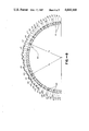
- FIGS. 7 and 8 are, respectively, partial plan and partial cross-section views of a magnetic coil assembly which incorporates aspects of the present invention.
- FIG. 9 is an enlarged view of a portion of FIG. 7, with the coil "unrolled” for clarity, and showing details of the coil end-mounting arrangement;
- FIG. 10 is an enlarged view of a portion of FIG. 7 showing the spacers in the coil end-mounting arrangement.
- FIG. 7 A diagrammatic illustration of an actual working example of a coil magnet assembly 49 which embodies the features of the present invention is shown in partial plan view in FIG. 7 and in cross-section in FIG. 8. While the invention is described relative to its use in a computed tomography scanner, it is applicable in general to deflecting magnets and to the function of scanning a beam of charged particles.
- the desired magnetic field magnitude and directional properties are provided by the particular configuration of magnet assembly 49, specifically the angular distribution ⁇ t of the wire turns, t, and the value of the total number of turns, T; the configuration of the end connections between the axially-extending sections of each wire turn, for example, the end connections between axial coil sections at ⁇ t and ⁇ - ⁇ t and between - ⁇ t and -( ⁇ - ⁇ t ) (see FIG. 4); and by equalization of the effective physical radii of the different coils.
- a shield 59 of very high permeability shields the region inside the magnet from external magnetic fields and increases and confines the field due to the windings.
- the magnetic shield design and construction also provide the desired equalization of the coil radii.
- FIG. 3 there is shown a highly schematized illustration of magnetic coil assembly such as the assembly 49 which is useful in considering the aspects of a pure dipole field.
- the magnetic coil assembly is defined with reference to arbitrarily designated mutually orthogonal coordinate axes x, y, z.
- one coil turn is shown from each of one of the continuous x-coils 51 and two continuous y-coils 53--53.
- the coil turns comprise axial sections which extend substantially parallel to the z-axis and end connections which interconnect the two axial sections of each coil turn.
- the cross-sectional planes of each coil lie within planes parallel to the xy plane and the location of the radius therein is defined by polar coordinates (r, ⁇ ).
- the plane of deflection of the magnetic field is the plane perpendicular to the magnetic field direction.
- the angular positions ⁇ t of the axial coil sections are chosen so that the magnetic coil assembly closely approximates the ideals expressed in equations (1) and (2), to the particular required accuracy or tolerance of 0.2%.
- the required accuracy of 0.2% is obtained if neither of the following root mean square (RMS) errors (associated, respectively, with the non-rotating magnetic field in the plane of FIG. 4 and the rotating field in the plane of deflection) exceeds 0.2% of the value of the magnetic field on the magnet axis 55 (FIG. 3).
- RMS root mean square
- error formulae (3) and (4) are conveniently evaluated using the approximation of an infinitely long deflecting magnet, i.e., without considering end effects.
- MNRES Minimum Non-Rotating Error Solution
- one or more of the other solutions may be applicable exclusive of, or in addition to, the ESSS solution in selecting the values of ⁇ t .
- These solutions include a class in which the angular positions ⁇ t of the axial sections 60 of each coil are treated as T independent parameters which are varied to minimize the previously-described RMS error for the non-rotating field or the previously-described RMS error for the rotating field.
- the coil assembly comprises a cylindrical coil form 57 (FIG. 8) of dielectric material such as resin-impregnated fiberglass, and an overlying magnetic shield 59 (FIG. 7).
- the coil form 57 has thirty-six slots 61--61 cut or otherwise formed in the outer surface thereof, individually designated X1-X36, for receiving the axial segments of like designation of a particular x-coil 51. (Only half the coil form is shown.)
- the form 57 has thirty-six slots 63--63, individually designated Y19-Y54, for receiving the axial segments of a particular y-coil.
- the x-coils are adjacent to one another and together span approximately 360° of arc.
- the x-coils and y-coils are rotated 90° relative to one another, and the y-coils are positioned at a slightly greater radius than the x-coils, as discussed below.
- the wire diameter is 0.109 inch.
- the x-coils are essentially identical to the y-coils except for their smaller radius and the 90° rotational displacement of their positions on the coil form 57.
- each of the coils was arranged in a continuous array of axial sections 60, individually designated X1-X36 (and X37-X72, Y19-Y54, Y55-Y18) which are substantially parallel to the cylinder axis 55 and which are joined by end connections or sections 67.
- the geometric configuration of the coil end sections 67--67 are ideally designed so that the field distribution due to the end connections is described by the same harmonic spectrum as that due to the axial parts of the windings.
- a method for achieving this result is described in Mills and Morgan, "A Flux Theorem for the Design of Magnet Coil Ends", Particle Accelerators, 5, 227, 1973.
- This configuration which may be adapted to any finite number of turns, is schematically shown in FIGS. 5 and 6 for four of the eighteen coil turns.
- each end connection 67 defines an angle, ⁇ , relative to its axial coil section 60 which is substantially equal to the angle, ⁇ , thereto defined by the curve 69.
- the curve 69 and end connections 67 are straight lines which define the equal angles ⁇ ' and ⁇ ' which assume equal values for each intersection 71 and its associated end connection. It is assumed that for a sufficiently large number of turns, the ideal mathematical properties of this configuration are approximated with the same accuracy as the uniformity of the field due to the axial parts of the windings.
- the end connections 67--67 for the x-coils and y-coils were implemented by applying the x-coils to the form 57, using end connection spacers 75--75 of appropriate length and using retaining spacers 77--77, all of which were glued to the coil form's peripheral end section slot 79 (which, unlike the central coil form, itself contains no slots).
- the spacers 75--75 define the above-discussed predetermined configuration of the coil end sections 67--67.
- liquid dielectric material such as epoxy resin was applied and cured to isolate the x-coils and provide a smooth base for the y-coils at the same level as the y-coil slots 63--63. Then, the appropriate sized end section spacers 75--75 and retaining spacers 77--77 were applied, followed by positioning of the y-coils, and application of another insulating layer 83 such as the above epoxy resin material. The coil assembly is thus ready for application of magnetic shield 59 described below, followed by a final insulative coating (not shown) of fiberglass tape or other suitable medium.
- the magnetic shield 59 of the present invention is a cylinder of inside radius R of high permeability material which is located on the outside of the coil form and serves three functions: (1) to shield the internal coil assembly region from external magnetic fields; (2) to increase and confine the field due to the windings; and (3) to equalize the effective radii of the x and y windings which are at different physical radii a x and a y .
- the radii equalization function of item (3) is thought to be novel; in constructing the magnetic shield 59 to specifications which satisfy this novel function, the shielding function and field-increasing and confining functions are thereby met.
- the magnetic shield 59 is located outside both coils and produces effective coil radii which are approximately equal, although the actual dimensions of the radii are different. Thus, one coil can be wound outside the other, thus simplifying construction considerably.
- This is the basis for the use, described previously, of the coil form 57 which has grooves therein for the y-coils and the x-coils, with the y-coils being wound outside the x-coils.
- the form 57 is amenable to forming grooves at precise locations to establish the angular location of the coil windings.
- the actual radii a x and a y of the coils are precisely defined and controlled by the coil form slots and the precisely-defined physical coil radii are then used in conjunction with the following design theory to provide equal effective radii, a EFF .
- the magnetic shield material was a very high permeability magnetic material such as that available under the tradename Moly Permalloy available from Allegheny Ludlum Steel, Corp., Pittsburgh, Pa.
- the dimensions of the shield were chosen so that its permeability was close to the maximum value for the Moly Permalloy, 300,000 to 500,000, a value sufficiently high for the expression (11) to be valid.
- the material comprised a tape 0.008 inches thick by 0.25 inch wide which was wound in 12 layers of overlapping helices, with the sense alternating with each layer, to reduce eddy currents.
- the percentage difference in the actual radii a x and a y was 1.03 percent.
- the difference in the corresponding a EFF is determined by the difference in the bracket terms of equation (11), i.e., 0.99967-0.99988.
- the effective radii of the x and y coils differ by only 0.021 percent, despite the 1.03 percent difference in actual radii.
- the unique magnetic shielding technique has provided the required equal effective coil radii using a simplified construction technique which affords very precise definition of the coils and their associated radii.
Landscapes
- Health & Medical Sciences (AREA)
- Life Sciences & Earth Sciences (AREA)
- Engineering & Computer Science (AREA)
- Medical Informatics (AREA)
- Radiology & Medical Imaging (AREA)
- Molecular Biology (AREA)
- Biophysics (AREA)
- Nuclear Medicine, Radiotherapy & Molecular Imaging (AREA)
- Optics & Photonics (AREA)
- Pathology (AREA)
- Physics & Mathematics (AREA)
- Biomedical Technology (AREA)
- Heart & Thoracic Surgery (AREA)
- High Energy & Nuclear Physics (AREA)
- Surgery (AREA)
- Animal Behavior & Ethology (AREA)
- General Health & Medical Sciences (AREA)
- Public Health (AREA)
- Veterinary Medicine (AREA)
- Pulmonology (AREA)
- Theoretical Computer Science (AREA)
- Magnetic Resonance Imaging Apparatus (AREA)
Abstract
Description
B.sub.x /B.sub.y =-tan φ, (2)
B.sub.x /B.sub.y =-tan φ (2)
θ.sub.t =(π/2)(1/3±1/5±1/7). (7)
              TABLE 1
______________________________________
Magnetic Field Non-Uniformity (RMS Errors)
For Long Cylindrical Magnets Using Various
Solutions for Wire Spacing
              RMS Error 1 RMS Error 2
              (Non-Rotating)
                          (Rotating)
Solution      Formula (3')
                          Formula (4')
______________________________________
4 Turns
(a) ZMS       3.45 × 10.sup.-2
                          4.61 × 10.sup.-2
(b) ESSS      1.95 × 10.sup.-2
                          1.16 × 10.sup.-2
(c) MESSS1    1.81 × 10.sup.-2
                          1.09 × 10.sup.-2
(d) MESSS2    1.84 × 10.sup.-2
                          1.07 × 10.sup.-2
(e) MNRES     1.77 × 10.sup.-2
                          1.21 × 10.sup.-2
(f) MRES       2.1 × 10.sup.-2
                          5.19 × 10.sup.-3
18 Turns
(b) ESSS      1.61 × 10.sup.-3
                           4.6 × 10.sup.-4
(c) MESSS1    1.27 × 10.sup.-3
                           8.4 × 10.sup.-4
(d) MESSS2    1.46 × 10.sup.-3
                           3.6 × 10.sup.-4
(e) MNRES      6.9 × 10.sup.-4
                           2.3 × 10.sup.-4
(f) MRES       7.8 × 10.sup.-4
                           3.5 × 10.sup.-5
______________________________________
              TABLE 2
______________________________________
Wire Positions (Values of θ.sub.t in Degrees) For
The Configurations of TABLE 1: 18 Turns
       ESSS  MESSS1   MESSS2   MNRES  MRES
______________________________________
t/Solution
1        1.592   1.477    1.557  1.570  1.570
2        4.780   4.665    4.746  4.768  4.848
3        7.984   7.868    7.949  7.932  7.920
4        11.212  11.095   11.177 11.143 10.933
5        14.478  14.359   14.442 14.436 14.493
6        17.792  17.671   17.755 17.630 18.023
7        21.168  21.046   21.132 21.100 20.994
8        24.624  24.498   24.587 24.495 24.250
9        28.179  28.049   28.140 27.900 28.063
10       31.855  31.721   31.815 31.893 31.734
11       35.685  35.544   35.643 35.172 35.541
12       39.709  39.560   39.664 39.767 39.546
13       43.983  43.824   43.935 43.382 43.611
14       48.590  48.417   48.538 48.517 48.230
15       53.664  53.471   53.606 52.977 53.405
16       59.442  59.217   59.374 59.210 59.133
17       66.444  66.158   66.358 65.391 65.368
18       76.464  75.983   76.318 75.927 76.268
Minimum Angular Separation
Δθ.sub.15
         -0.651  -0.985   -0.751 -1.851 -1.054
Δθ.sub.16
         1.297   0.938    1.189  1.103  0.867
Δθ.sub.17
         1.068   0.656    0.945  -0.114 -0.382
Δθ.sub.18
         0.942   0.342    0.760  0.363  0.761
______________________________________
a.sub.EFF =R[1-1/2(ΔR/R).sup.2 + . . . ] (11)
Claims (10)
B.sub.o =(B.sub.x.sup.2 +B.sub.y.sup.2).sup.1/2,
B.sub.x /B.sub.y =-tan φ,
______________________________________
t =        1         θ.sub.t ≈
                            1.59°
           2                4.78°
           3                7.98°
           4                11.21°
           5                14.48°
           6                17.79°
           7                21.17°
           8                24.62°
           9                28.18°
          10                31.86°
          11                35.69°
          12                39.71°
          13                43.98°
          14                48.59°
          15                53.66°
          16                59.44°
          17                66.44°
          18                76.46°
______________________________________
Priority Applications (1)
| Application Number | Priority Date | Filing Date | Title |
|---|---|---|---|
| US06/610,102 US4644168A (en) | 1984-05-14 | 1984-05-14 | Electron beam deflecting magnet assembly for a scanning electron beam computed tomography scanner |
Applications Claiming Priority (1)
| Application Number | Priority Date | Filing Date | Title |
|---|---|---|---|
| US06/610,102 US4644168A (en) | 1984-05-14 | 1984-05-14 | Electron beam deflecting magnet assembly for a scanning electron beam computed tomography scanner |
Publications (1)
| Publication Number | Publication Date |
|---|---|
| US4644168A true US4644168A (en) | 1987-02-17 |
Family
ID=24443657
Family Applications (1)
| Application Number | Title | Priority Date | Filing Date |
|---|---|---|---|
| US06/610,102 Expired - Lifetime US4644168A (en) | 1984-05-14 | 1984-05-14 | Electron beam deflecting magnet assembly for a scanning electron beam computed tomography scanner |
Country Status (1)
| Country | Link |
|---|---|
| US (1) | US4644168A (en) |
Cited By (16)
| Publication number | Priority date | Publication date | Assignee | Title |
|---|---|---|---|---|
| US5193105A (en) * | 1991-12-18 | 1993-03-09 | Imatron, Inc. | Ion controlling electrode assembly for a scanning electron beam computed tomography scanner |
| US5241577A (en) * | 1992-01-06 | 1993-08-31 | Picker International, Inc. | X-ray tube with bearing slip ring |
| US5274690A (en) * | 1992-01-06 | 1993-12-28 | Picker International, Inc. | Rotating housing and anode/stationary cathode x-ray tube with magnetic susceptor for holding the cathode stationary |
| US5438605A (en) * | 1992-01-06 | 1995-08-01 | Picker International, Inc. | Ring tube x-ray source with active vacuum pumping |
| US5712889A (en) * | 1994-08-24 | 1998-01-27 | Lanzara; Giovanni | Scanned volume CT scanner |
| US6670625B1 (en) | 2002-06-18 | 2003-12-30 | Ge Medical Systems Global Technology Company, Llc | Method and apparatus for correcting multipole aberrations of an electron beam in an EBT scanner |
| US20040091079A1 (en) * | 2002-11-12 | 2004-05-13 | Zapalac Geordie Henry | Method and apparatus for scatter measurement using an occluded detector ring |
| US20040096027A1 (en) * | 2002-11-15 | 2004-05-20 | Zapalac Geordie Henry | Method and apparatus for connecting temporally separated sinograms in an EBT scanner |
| NL1024724C2 (en) | 2002-11-12 | 2005-05-04 | Ge Med Sys Global Tech Co Llc | System and method for measuring a local lung function using electron beam CT. |
| WO2008103747A1 (en) * | 2007-02-21 | 2008-08-28 | L-3 Communications Corporation | Compact scanned electron-beam x-ray source |
| US7447536B2 (en) | 2002-11-12 | 2008-11-04 | G.E. Medical Systems Global Technology Company, Llc | System and method for measurement of local lung function using electron beam CT |
| US8618521B2 (en) | 2012-03-03 | 2013-12-31 | The Board Of Trustees Of The Leland Stanford Junior University | Pluridirectional very high electron energy radiation therapy systems and processes |
| US20150279496A1 (en) * | 2012-03-25 | 2015-10-01 | Arp Angewandte Radiologische Physik Ug (Haftungsbeschrankt) | Phase Contrast X-Ray Tomography Device |
| US20160027606A1 (en) * | 2013-04-09 | 2016-01-28 | Helmholtz-Zentrum Dresden-Rossendorf E.V. | Arrangement for a quick electron beam x-ray computer tomography |
| US9931522B2 (en) | 2013-09-11 | 2018-04-03 | The Board Of Trustees Of The Leland Stanford Junior University | Methods and systems for beam intensity-modulation to facilitate rapid radiation therapies |
| US10485991B2 (en) | 2013-09-11 | 2019-11-26 | The Board Of Trustees Of The Leland Stanford Junior University | Methods and systems for RF power generation and distribution to facilitate rapid radiation therapies |
Citations (6)
| Publication number | Priority date | Publication date | Assignee | Title |
|---|---|---|---|---|
| US3007087A (en) * | 1958-06-04 | 1961-10-31 | Gen Dynamics Corp | Electromagnetic deflection coil |
| US3430169A (en) * | 1965-10-23 | 1969-02-25 | Sanders Associates Inc | Deflection yoke |
| US3731241A (en) * | 1969-09-18 | 1973-05-01 | Science Res Council | Electrical coils for generating magnetic fields |
| US3911321A (en) * | 1971-11-26 | 1975-10-07 | Ibm | Error compensating deflection coils in a conducting magnetic tube |
| US4122346A (en) * | 1977-03-23 | 1978-10-24 | High Voltage Engineering Corporation | Optical devices for computed transaxial tomography |
| US4352021A (en) * | 1980-01-07 | 1982-09-28 | The Regents Of The University Of California | X-Ray transmission scanning system and method and electron beam X-ray scan tube for use therewith |
-
1984
- 1984-05-14 US US06/610,102 patent/US4644168A/en not_active Expired - Lifetime
Patent Citations (6)
| Publication number | Priority date | Publication date | Assignee | Title |
|---|---|---|---|---|
| US3007087A (en) * | 1958-06-04 | 1961-10-31 | Gen Dynamics Corp | Electromagnetic deflection coil |
| US3430169A (en) * | 1965-10-23 | 1969-02-25 | Sanders Associates Inc | Deflection yoke |
| US3731241A (en) * | 1969-09-18 | 1973-05-01 | Science Res Council | Electrical coils for generating magnetic fields |
| US3911321A (en) * | 1971-11-26 | 1975-10-07 | Ibm | Error compensating deflection coils in a conducting magnetic tube |
| US4122346A (en) * | 1977-03-23 | 1978-10-24 | High Voltage Engineering Corporation | Optical devices for computed transaxial tomography |
| US4352021A (en) * | 1980-01-07 | 1982-09-28 | The Regents Of The University Of California | X-Ray transmission scanning system and method and electron beam X-ray scan tube for use therewith |
Non-Patent Citations (2)
| Title |
|---|
| Mills et al., "A Flux Theorem for the Design of Magnet Coil Ends," Particle Accelerators, vol. 5, pp. 227-235 (1973). |
| Mills et al., A Flux Theorem for the Design of Magnet Coil Ends, Particle Accelerators, vol. 5, pp. 227 235 (1973). * |
Cited By (25)
| Publication number | Priority date | Publication date | Assignee | Title |
|---|---|---|---|---|
| US5193105A (en) * | 1991-12-18 | 1993-03-09 | Imatron, Inc. | Ion controlling electrode assembly for a scanning electron beam computed tomography scanner |
| US5241577A (en) * | 1992-01-06 | 1993-08-31 | Picker International, Inc. | X-ray tube with bearing slip ring |
| US5274690A (en) * | 1992-01-06 | 1993-12-28 | Picker International, Inc. | Rotating housing and anode/stationary cathode x-ray tube with magnetic susceptor for holding the cathode stationary |
| US5438605A (en) * | 1992-01-06 | 1995-08-01 | Picker International, Inc. | Ring tube x-ray source with active vacuum pumping |
| US5712889A (en) * | 1994-08-24 | 1998-01-27 | Lanzara; Giovanni | Scanned volume CT scanner |
| US6670625B1 (en) | 2002-06-18 | 2003-12-30 | Ge Medical Systems Global Technology Company, Llc | Method and apparatus for correcting multipole aberrations of an electron beam in an EBT scanner |
| US7447536B2 (en) | 2002-11-12 | 2008-11-04 | G.E. Medical Systems Global Technology Company, Llc | System and method for measurement of local lung function using electron beam CT |
| US6789943B2 (en) | 2002-11-12 | 2004-09-14 | Ge Medical Systems Global Technology Company, Llc | Method and apparatus for scatter measurement using an occluded detector ring |
| NL1024724C2 (en) | 2002-11-12 | 2005-05-04 | Ge Med Sys Global Tech Co Llc | System and method for measuring a local lung function using electron beam CT. |
| US20040091079A1 (en) * | 2002-11-12 | 2004-05-13 | Zapalac Geordie Henry | Method and apparatus for scatter measurement using an occluded detector ring |
| US20040096027A1 (en) * | 2002-11-15 | 2004-05-20 | Zapalac Geordie Henry | Method and apparatus for connecting temporally separated sinograms in an EBT scanner |
| US6842499B2 (en) | 2002-11-15 | 2005-01-11 | Ge Medical Systems Global Technology Company, Llc | Method and apparatus for connecting temporally separated sinograms in an EBT scanner |
| WO2008103747A1 (en) * | 2007-02-21 | 2008-08-28 | L-3 Communications Corporation | Compact scanned electron-beam x-ray source |
| US7639785B2 (en) | 2007-02-21 | 2009-12-29 | L-3 Communications Corporation | Compact scanned electron-beam x-ray source |
| US9018603B2 (en) | 2012-03-03 | 2015-04-28 | The Board Of Trustees Of The Leland Stanford Junior University | Pluridirectional very high electron energy radiation therapy systems and processes |
| US8618521B2 (en) | 2012-03-03 | 2013-12-31 | The Board Of Trustees Of The Leland Stanford Junior University | Pluridirectional very high electron energy radiation therapy systems and processes |
| US20150279496A1 (en) * | 2012-03-25 | 2015-10-01 | Arp Angewandte Radiologische Physik Ug (Haftungsbeschrankt) | Phase Contrast X-Ray Tomography Device |
| US10076297B2 (en) * | 2012-03-25 | 2018-09-18 | Arp Angewandte Radiologische Physik Ug (Haftungsbeschrankt) | Phase contrast X-ray tomography device |
| US20160027606A1 (en) * | 2013-04-09 | 2016-01-28 | Helmholtz-Zentrum Dresden-Rossendorf E.V. | Arrangement for a quick electron beam x-ray computer tomography |
| US9931522B2 (en) | 2013-09-11 | 2018-04-03 | The Board Of Trustees Of The Leland Stanford Junior University | Methods and systems for beam intensity-modulation to facilitate rapid radiation therapies |
| US9962562B2 (en) | 2013-09-11 | 2018-05-08 | The Board Of Trustees Of The Leland Stanford Junior University | Arrays of accelerating structures and rapid imaging for facilitating rapid radiation therapies |
| US10485991B2 (en) | 2013-09-11 | 2019-11-26 | The Board Of Trustees Of The Leland Stanford Junior University | Methods and systems for RF power generation and distribution to facilitate rapid radiation therapies |
| US10576303B2 (en) | 2013-09-11 | 2020-03-03 | The Board of Trsutees of the Leland Stanford Junior University | Methods and systems for beam intensity-modulation to facilitate rapid radiation therapies |
| US10806950B2 (en) | 2013-09-11 | 2020-10-20 | The Board Of Trustees Of The Leland Stanford Junior University | Rapid imaging systems and methods for facilitating rapid radiation therapies |
| USRE50811E1 (en) | 2013-09-11 | 2026-03-10 | The Board Of Trustees Of The Leland Stanford Junior University | Rapid imaging systems and methods for facilitating rapid radiation therapies |
Similar Documents
| Publication | Publication Date | Title |
|---|---|---|
| US4644168A (en) | Electron beam deflecting magnet assembly for a scanning electron beam computed tomography scanner | |
| US3984687A (en) | Shielded magnetic lens and deflection yoke structure for electron beam column | |
| US8424193B2 (en) | Method of providing and operating a conductor assembly | |
| Beaty | Calculated electrostatic properties of ion traps | |
| WO2009073272A2 (en) | Conductor assembly and methods of fabricating a conductor assembly | |
| JPH10125497A (en) | Inductive coupling source for inducing almost uniform plasma flux | |
| JPS5924520B2 (en) | Structure of the magnetic pole of an isochronous cyclotron and how to use it | |
| JPS61742A (en) | High-frequency coil device for nuclear magnetic resonance (nmr) mapping device | |
| JPH04273409A (en) | Superconducting magnet device and particle accelerator using the superconducting magnet device | |
| US4392078A (en) | Electron discharge device with a spatially periodic focused beam | |
| US4823003A (en) | Charged particle optical systems having therein means for correcting aberrations | |
| US4727249A (en) | Magnetic sector mass spectrometer | |
| US4251728A (en) | Compensated magnetic deflection coil for electron beam lithography system | |
| Persico | A Theory of the Solenoid Beta‐Ray Spectrometer | |
| US4153889A (en) | Method and device for generating a magnetic field of a potential with electric current components distributed according to a derivative of the potential | |
| JPH0616388B2 (en) | Magnetic coil assembly for adjusting and deflecting incident electron beam in an electron beam system such as a fault scanner using a computer | |
| JPS63294187A (en) | Picture display device | |
| Hart | The effect of a tilted magnetic field on the equilibrium of a pure electron plasma | |
| US4400622A (en) | Electron lens equipment | |
| US4095202A (en) | Coil for producing a homogeneous magnetic field in a cylindrical space | |
| US5469017A (en) | Permanent magnet focus unit with integral astigmatism corrector | |
| WO2011061537A1 (en) | Magnets | |
| US2964627A (en) | Double-focussing spectrometer for electrically charged particles | |
| Caspi et al. | A conical accelerator magnet with unique CCT properties | |
| Wollnik | The correction of image aberrations of second order for mass or energy separators consisting of one single magnetic sector field |
Legal Events
| Date | Code | Title | Description |
|---|---|---|---|
| AS | Assignment |
Owner name: IMATRON INC. SOUTH SAN FRANCISCO CA A CORP OF CA Free format text: ASSIGNMENT OF ASSIGNORS INTEREST.;ASSIGNORS:RAND, ROY E.;WANG, DAN Y.;REEL/FRAME:004293/0349 Effective date: 19840510 |
|
| STCF | Information on status: patent grant |
Free format text: PATENTED CASE |
|
| CC | Certificate of correction | ||
| FEPP | Fee payment procedure |
Free format text: PAYOR NUMBER ASSIGNED (ORIGINAL EVENT CODE: ASPN); ENTITY STATUS OF PATENT OWNER: LARGE ENTITY |
|
| FPAY | Fee payment |
Year of fee payment: 4 |
|
| FEPP | Fee payment procedure |
Free format text: PAT HLDR NO LONGER CLAIMS SMALL ENT STAT AS SMALL BUSINESS (ORIGINAL EVENT CODE: LSM2); ENTITY STATUS OF PATENT OWNER: LARGE ENTITY |
|
| FPAY | Fee payment |
Year of fee payment: 8 |
|
| FPAY | Fee payment |
Year of fee payment: 12 |
|
| AS | Assignment |
Owner name: GE MEDICAL SYSTEMS GLOBAL TECHNOLOGY COMPANY, LLC, Free format text: MERGER;ASSIGNOR:IMATRON INC.;REEL/FRAME:012822/0326 Effective date: 20011219 |