US4643153A - Electronic arrangement for generating a fuel metering signal for an internal combustion engine - Google Patents
Electronic arrangement for generating a fuel metering signal for an internal combustion engine Download PDFInfo
- Publication number
- US4643153A US4643153A US06/777,639 US77763985A US4643153A US 4643153 A US4643153 A US 4643153A US 77763985 A US77763985 A US 77763985A US 4643153 A US4643153 A US 4643153A
- Authority
- US
- United States
- Prior art keywords
- metering signal
- electronic arrangement
- batt
- correction
- battery voltage
- Prior art date
- Legal status (The legal status is an assumption and is not a legal conclusion. Google has not performed a legal analysis and makes no representation as to the accuracy of the status listed.)
- Expired - Fee Related
Links
Images
Classifications
-
- F—MECHANICAL ENGINEERING; LIGHTING; HEATING; WEAPONS; BLASTING
- F02—COMBUSTION ENGINES; HOT-GAS OR COMBUSTION-PRODUCT ENGINE PLANTS
- F02D—CONTROLLING COMBUSTION ENGINES
- F02D41/00—Electrical control of supply of combustible mixture or its constituents
- F02D41/24—Electrical control of supply of combustible mixture or its constituents characterised by the use of digital means
- F02D41/2406—Electrical control of supply of combustible mixture or its constituents characterised by the use of digital means using essentially read only memories
-
- F—MECHANICAL ENGINEERING; LIGHTING; HEATING; WEAPONS; BLASTING
- F02—COMBUSTION ENGINES; HOT-GAS OR COMBUSTION-PRODUCT ENGINE PLANTS
- F02D—CONTROLLING COMBUSTION ENGINES
- F02D41/00—Electrical control of supply of combustible mixture or its constituents
- F02D41/30—Controlling fuel injection
- F02D41/3005—Details not otherwise provided for
-
- F—MECHANICAL ENGINEERING; LIGHTING; HEATING; WEAPONS; BLASTING
- F02—COMBUSTION ENGINES; HOT-GAS OR COMBUSTION-PRODUCT ENGINE PLANTS
- F02D—CONTROLLING COMBUSTION ENGINES
- F02D2200/00—Input parameters for engine control
- F02D2200/50—Input parameters for engine control said parameters being related to the vehicle or its components
- F02D2200/503—Battery correction, i.e. corrections as a function of the state of the battery, its output or its type
Definitions
- the invention relates to an electronic arrangement for generating a fuel metering signal for an internal combustion engine in dependence upon operating characteristic quantities and a correction of the battery voltage.
- a basic injection signal is formed in dependence on engine speed and load which, among others, is then also corrected in dependence on the battery voltage.
- the reason for this is that the pick-up time of injection depends to a substantial degree on the battery voltage. If the voltage were not corrected electronically, a delayed response of the injection valves ensuing therefrom would result in an insufficient duration of injection and thus an insufficient quantity of fuel injected. The lower the battery voltage, the less fuel would be supplied to the internal combustion engine.
- the voltage correction acts additively and is generated by means of a characteristic curve. This voltage correction is taken as a separate correction quantity.
- the electronic arrangement of the invention for generating a fuel metering signal makes it possible to correct the battery voltage very accurately and thereby actually deliver the desired amount of fuel to the engine. With a view to low pollutant emissions and optimum operation of the internal combustion engine, the arrangement of the invention has proved to be highly efficient.
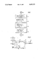
- FIG. 1 is a flowchart illustrating the computation sequence of an injection duration signal formed pursuant to the invention.
- FIG. 2 is a block diagram explaining the invention by way of example with reference to a circuit configuration.
- the embodiments relate to arrangements of the invention for a spark ignition internal combustion engine having intermittent injection.
- FIG. 1 shows in rough outline the computation sequence of a signal indicative of the duration of injection that is formed in accordance with the invention.
- the program starts at reference numeral 10. Then follows a block 11 in which the individual control quantities x n such as engine speed, load and temperature are read in. The next block 12 serves to compute a basic duration of injection tio in dependence on the control quantities x n . It is followed by block 13 in which a correction quantity tv is formed as a function g of the battery voltage and of further quantities. This correction quantity is shown in block 13 of FIG. 1 as
- a block 14 serves to compute the overall function for the duration of injection
- the correction quantity is formed in dependence on the battery voltage U Batt with at least one further quantity y being utilized.
- This is realized, for example, by means of a characteristic field for the correction quantity wherein at least one dimension of the correction quantity is the battery voltage.
- This arrangement ensures that the correction of the battery voltage does not depend solely on the battery voltage but may be referred to at least one further quantity. In contrast to the pure characteristic control as known in the art, this arrangement permits a substantially finer adjustment.
- the computation of the correction value tv has yielded the engine speed for the further independent quantity y.
- the air flow rate or the basic injection signal tio is used as the quantity y which ultimately corresponds to the quotient of load and engine speed (corrected, if necessary, by means of temperature values).
- reference numeral 20 identifies a basic injection pulse generator receiving input quantities from a temperature sensor 21, an engine speed sensor 22 and a load sensor 23.
- the basic injection pulse generator 20 is followed by a correcting stage 24 and finally an injection valve 25.
- Reference numeral 26 identifies a correction signal generator which receives a battery voltage signal at its control input 27 as well as receiving selectively at least one of the output quantities of sensors 21 to 23 or the output quantities of basic injection pulse generator 20.
- the correction of the basic injection signal in correcting element 24 may be accomplished additively and/or multiplicatively.
- correction signal generator 26 is made up of a three-dimensional characteristic field including the independent variables battery voltage and one of the quantities engine speed, load, basic duration of injection or temperature. It is to be understood that correction signal generator 25 may also include a higher dimensional characteristic field. It is only necessary to ensure that the correction quantity is not only influenced by the battery voltage but also by further operating characteristics.
Landscapes
- Engineering & Computer Science (AREA)
- Chemical & Material Sciences (AREA)
- Combustion & Propulsion (AREA)
- Mechanical Engineering (AREA)
- General Engineering & Computer Science (AREA)
- Electrical Control Of Air Or Fuel Supplied To Internal-Combustion Engine (AREA)
- Investigating Or Analyzing Materials By The Use Of Electric Means (AREA)
- Combined Controls Of Internal Combustion Engines (AREA)
Abstract
Description
tv=g (U.sub.Batt, y)
ti=f [x.sub.n, g (U.sub.Batt, y)].
Claims (7)
ti=f[x.sub.n, g(U.sub.Batt, y)]
Applications Claiming Priority (2)
| Application Number | Priority Date | Filing Date | Title |
|---|---|---|---|
| DE19843434339 DE3434339A1 (en) | 1984-09-19 | 1984-09-19 | ELECTRONIC DEVICE FOR GENERATING A FUEL MEASURING SIGNAL FOR AN INTERNAL COMBUSTION ENGINE |
| DE3434339 | 1984-09-19 |
Publications (1)
| Publication Number | Publication Date |
|---|---|
| US4643153A true US4643153A (en) | 1987-02-17 |
Family
ID=6245765
Family Applications (1)
| Application Number | Title | Priority Date | Filing Date |
|---|---|---|---|
| US06/777,639 Expired - Fee Related US4643153A (en) | 1984-09-19 | 1985-09-19 | Electronic arrangement for generating a fuel metering signal for an internal combustion engine |
Country Status (4)
| Country | Link |
|---|---|
| US (1) | US4643153A (en) |
| EP (1) | EP0175162A3 (en) |
| JP (1) | JPS6176732A (en) |
| DE (1) | DE3434339A1 (en) |
Cited By (4)
| Publication number | Priority date | Publication date | Assignee | Title |
|---|---|---|---|---|
| US4681076A (en) * | 1984-12-13 | 1987-07-21 | Robert Bosch Gmbh | Electronically controlled fuel injection system for an internal combustion engine |
| US5161510A (en) * | 1989-12-27 | 1992-11-10 | Yamaha Hatsudoki Kabushiki Kaisha | Electrically operated fuel injector |
| US5474054A (en) * | 1993-12-27 | 1995-12-12 | Ford Motor Company | Fuel injection control system with compensation for pressure and temperature effects on injector performance |
| CN103527338A (en) * | 2013-10-29 | 2014-01-22 | 潍柴动力股份有限公司 | Oil injection correction method and system |
Families Citing this family (5)
| Publication number | Priority date | Publication date | Assignee | Title |
|---|---|---|---|---|
| JPS61255234A (en) * | 1985-05-08 | 1986-11-12 | Honda Motor Co Ltd | Fuel feed control on start of internal-combustion engine |
| DE3924353A1 (en) * | 1989-07-22 | 1991-02-14 | Prufrex Elektro App | CONTROL SYSTEM FOR THE CARBURETOR OF AN INTERNAL COMBUSTION ENGINE |
| US5279272A (en) * | 1991-06-19 | 1994-01-18 | Volkswagen Ag | Method and apparatus for controlling fuel injection valves in an internal combustion engine |
| DE4120116A1 (en) * | 1991-06-19 | 1992-12-24 | Volkswagen Ag | METHOD AND ARRANGEMENT FOR GENERATING ACTUATION PULSES FOR FUEL INJECTION VALVES OF AN INTERNAL COMBUSTION ENGINE |
| JP6289579B1 (en) | 2016-10-20 | 2018-03-07 | 三菱電機株式会社 | INJECTOR CONTROL DEVICE AND INJECTOR CONTROL METHOD |
Citations (6)
| Publication number | Priority date | Publication date | Assignee | Title |
|---|---|---|---|---|
| US3683871A (en) * | 1970-07-17 | 1972-08-15 | Gen Motors Corp | Fuel supply system for an internal combustion engine providing voltage compensated cranking enrichment |
| JPS5828537A (en) * | 1981-07-24 | 1983-02-19 | Toyota Motor Corp | Electronically controlled fuel injection process and equipment in internal combustion engine |
| JPS5828540A (en) * | 1981-07-24 | 1983-02-19 | Toyota Motor Corp | Electronically controlled fuel injection process and equipment in internal combustion engine |
| US4438748A (en) * | 1981-03-04 | 1984-03-27 | Nissan Motor Co., Ltd. | Method of supplying fuel to an internal combustion engine during start-up |
| US4515130A (en) * | 1982-05-17 | 1985-05-07 | Honda Motor Co., Ltd. | Method for controlling fuel supply to an internal combustion engine at deceleration |
| US4543937A (en) * | 1983-03-15 | 1985-10-01 | Toyota Jidosha Kabushiki Kaisha | Method and apparatus for controlling fuel injection rate in internal combustion engine |
Family Cites Families (5)
| Publication number | Priority date | Publication date | Assignee | Title |
|---|---|---|---|---|
| US3896773A (en) * | 1972-10-27 | 1975-07-29 | Gen Motors Corp | Electronic fuel injection system |
| US4184460A (en) * | 1976-05-28 | 1980-01-22 | Nippondenso Co., Ltd. | Electronically-controlled fuel injection system |
| DE2700628A1 (en) * | 1977-01-08 | 1978-07-20 | Bosch Gmbh Robert | METHOD AND DEVICE FOR CORRECTING THE DURATION OF INJECTION PULSES SUPPLIED BY ELECTROMAGNETIC INJECTION VALVES, DEPENDING ON THE LOAD STATE |
| JPS57108427A (en) * | 1980-12-26 | 1982-07-06 | Nissan Motor Co Ltd | Controller of delivery fuel from motor-driven fuel pump |
| JPS60150450A (en) * | 1984-01-18 | 1985-08-08 | Honda Motor Co Ltd | Feedback control method of idle number of revolution of internal-combustion engine |
-
1984
- 1984-09-19 DE DE19843434339 patent/DE3434339A1/en not_active Withdrawn
-
1985
- 1985-08-22 EP EP85110553A patent/EP0175162A3/en not_active Ceased
- 1985-08-27 JP JP60186787A patent/JPS6176732A/en active Pending
- 1985-09-19 US US06/777,639 patent/US4643153A/en not_active Expired - Fee Related
Patent Citations (6)
| Publication number | Priority date | Publication date | Assignee | Title |
|---|---|---|---|---|
| US3683871A (en) * | 1970-07-17 | 1972-08-15 | Gen Motors Corp | Fuel supply system for an internal combustion engine providing voltage compensated cranking enrichment |
| US4438748A (en) * | 1981-03-04 | 1984-03-27 | Nissan Motor Co., Ltd. | Method of supplying fuel to an internal combustion engine during start-up |
| JPS5828537A (en) * | 1981-07-24 | 1983-02-19 | Toyota Motor Corp | Electronically controlled fuel injection process and equipment in internal combustion engine |
| JPS5828540A (en) * | 1981-07-24 | 1983-02-19 | Toyota Motor Corp | Electronically controlled fuel injection process and equipment in internal combustion engine |
| US4515130A (en) * | 1982-05-17 | 1985-05-07 | Honda Motor Co., Ltd. | Method for controlling fuel supply to an internal combustion engine at deceleration |
| US4543937A (en) * | 1983-03-15 | 1985-10-01 | Toyota Jidosha Kabushiki Kaisha | Method and apparatus for controlling fuel injection rate in internal combustion engine |
Cited By (6)
| Publication number | Priority date | Publication date | Assignee | Title |
|---|---|---|---|---|
| US4681076A (en) * | 1984-12-13 | 1987-07-21 | Robert Bosch Gmbh | Electronically controlled fuel injection system for an internal combustion engine |
| US5161510A (en) * | 1989-12-27 | 1992-11-10 | Yamaha Hatsudoki Kabushiki Kaisha | Electrically operated fuel injector |
| US5474054A (en) * | 1993-12-27 | 1995-12-12 | Ford Motor Company | Fuel injection control system with compensation for pressure and temperature effects on injector performance |
| AU680566B2 (en) * | 1993-12-27 | 1997-07-31 | Ford Motor Company Of Canada Limited | Fuel injection control system with compensation for pressure and temperature effects on injector performance |
| CN103527338A (en) * | 2013-10-29 | 2014-01-22 | 潍柴动力股份有限公司 | Oil injection correction method and system |
| CN103527338B (en) * | 2013-10-29 | 2016-03-16 | 潍柴动力股份有限公司 | A kind of oil injection correction method and system |
Also Published As
| Publication number | Publication date |
|---|---|
| EP0175162A2 (en) | 1986-03-26 |
| EP0175162A3 (en) | 1987-01-14 |
| JPS6176732A (en) | 1986-04-19 |
| DE3434339A1 (en) | 1986-03-27 |
Similar Documents
| Publication | Publication Date | Title |
|---|---|---|
| US5131371A (en) | Method and arrangement for controlling a self-igniting internal combustion engine | |
| US6367454B1 (en) | Method for operating an internal combustion engine mainly in a motor vehicle | |
| US4789939A (en) | Adaptive air fuel control using hydrocarbon variability feedback | |
| US4466406A (en) | Regulating device for control variables of an internal combustion engine | |
| US4327682A (en) | Fuel supply system for an internal combustion engine | |
| GB2205663A (en) | Adaptive lean limit air fuel control using combustion pressure sensor feedback | |
| US4643153A (en) | Electronic arrangement for generating a fuel metering signal for an internal combustion engine | |
| US4469074A (en) | Electronic control for internal combustion engine | |
| US4250853A (en) | Method and apparatus for controlling the fuel supply of an internal combustion engine | |
| US4738238A (en) | Air-fuel ratio control system for an automotive engine | |
| GB2169108A (en) | Air-fuel ratio control system for an automotive engine | |
| US4171692A (en) | Fuel injection control system | |
| US4884548A (en) | Fuel injection control system for an automotive engine | |
| US4741312A (en) | Air-fuel ration control system for an automotive engine | |
| US5101797A (en) | Control system for a diesel internal combustion engine | |
| US4803966A (en) | Engine control system | |
| US4180023A (en) | Electronically-controlled fuel injection system for internal combustion engine having odd numbers of cylinders | |
| US5023795A (en) | Fuel injection control system for internal combustion engine with compensation of fuel amount consumed for wetting induction path | |
| US4572142A (en) | Arrangement for supplying a maximum quantity of fuel | |
| JPH0275760A (en) | Ignition timing control device for internal combustion engine | |
| US4771753A (en) | Air-fuel ratio control system for an automotive engine | |
| US4387687A (en) | Control apparatus for a fuel metering system in an internal combustion engine | |
| US5479910A (en) | Method and device for controlling an internal combustion engine | |
| US4640253A (en) | Electronic fuel injection control with variable injection timing | |
| GB2193014A (en) | Fuel injection control |
Legal Events
| Date | Code | Title | Description |
|---|---|---|---|
| AS | Assignment |
Owner name: ROBERT BOSCH GMBH, STUTTGART, GERMANY, ROBERT-BOSC Free format text: ASSIGNMENT OF ASSIGNORS INTEREST.;ASSIGNORS:CLEMENT, ALBRECHT;VIRGILIO, GUSTAV;WELLER, HUGO;REEL/FRAME:004461/0790;SIGNING DATES FROM 19850910 TO 19850916 |
|
| FEPP | Fee payment procedure |
Free format text: PAYOR NUMBER ASSIGNED (ORIGINAL EVENT CODE: ASPN); ENTITY STATUS OF PATENT OWNER: LARGE ENTITY |
|
| FPAY | Fee payment |
Year of fee payment: 4 |
|
| FPAY | Fee payment |
Year of fee payment: 8 |
|
| FEPP | Fee payment procedure |
Free format text: PAYER NUMBER DE-ASSIGNED (ORIGINAL EVENT CODE: RMPN); ENTITY STATUS OF PATENT OWNER: LARGE ENTITY Free format text: PAYOR NUMBER ASSIGNED (ORIGINAL EVENT CODE: ASPN); ENTITY STATUS OF PATENT OWNER: LARGE ENTITY |
|
| REMI | Maintenance fee reminder mailed | ||
| LAPS | Lapse for failure to pay maintenance fees | ||
| FP | Lapsed due to failure to pay maintenance fee |
Effective date: 19990217 |
|
| STCH | Information on status: patent discontinuation |
Free format text: PATENT EXPIRED DUE TO NONPAYMENT OF MAINTENANCE FEES UNDER 37 CFR 1.362 |