US4640734A - Method and apparatus for assembling large panels - Google Patents
Method and apparatus for assembling large panels Download PDFInfo
- Publication number
- US4640734A US4640734A US06/613,853 US61385384A US4640734A US 4640734 A US4640734 A US 4640734A US 61385384 A US61385384 A US 61385384A US 4640734 A US4640734 A US 4640734A
- Authority
- US
- United States
- Prior art keywords
- press
- frame
- rack
- support members
- sections
- Prior art date
- Legal status (The legal status is an assumption and is not a legal conclusion. Google has not performed a legal analysis and makes no representation as to the accuracy of the status listed.)
- Expired - Fee Related
Links
Images


Classifications
-
- B—PERFORMING OPERATIONS; TRANSPORTING
- B23—MACHINE TOOLS; METAL-WORKING NOT OTHERWISE PROVIDED FOR
- B23P—METAL-WORKING NOT OTHERWISE PROVIDED FOR; COMBINED OPERATIONS; UNIVERSAL MACHINE TOOLS
- B23P21/00—Machines for assembling a multiplicity of different parts to compose units, with or without preceding or subsequent working of such parts, e.g. with program control
-
- Y—GENERAL TAGGING OF NEW TECHNOLOGICAL DEVELOPMENTS; GENERAL TAGGING OF CROSS-SECTIONAL TECHNOLOGIES SPANNING OVER SEVERAL SECTIONS OF THE IPC; TECHNICAL SUBJECTS COVERED BY FORMER USPC CROSS-REFERENCE ART COLLECTIONS [XRACs] AND DIGESTS
- Y10—TECHNICAL SUBJECTS COVERED BY FORMER USPC
- Y10T—TECHNICAL SUBJECTS COVERED BY FORMER US CLASSIFICATION
- Y10T156/00—Adhesive bonding and miscellaneous chemical manufacture
- Y10T156/10—Methods of surface bonding and/or assembly therefor
- Y10T156/1089—Methods of surface bonding and/or assembly therefor of discrete laminae to single face of additional lamina
-
- Y—GENERAL TAGGING OF NEW TECHNOLOGICAL DEVELOPMENTS; GENERAL TAGGING OF CROSS-SECTIONAL TECHNOLOGIES SPANNING OVER SEVERAL SECTIONS OF THE IPC; TECHNICAL SUBJECTS COVERED BY FORMER USPC CROSS-REFERENCE ART COLLECTIONS [XRACs] AND DIGESTS
- Y10—TECHNICAL SUBJECTS COVERED BY FORMER USPC
- Y10T—TECHNICAL SUBJECTS COVERED BY FORMER US CLASSIFICATION
- Y10T156/00—Adhesive bonding and miscellaneous chemical manufacture
- Y10T156/17—Surface bonding means and/or assemblymeans with work feeding or handling means
- Y10T156/1702—For plural parts or plural areas of single part
- Y10T156/1744—Means bringing discrete articles into assembled relationship
- Y10T156/1751—At least three articles
- Y10T156/1754—At least two applied side by side to common base
- Y10T156/1759—Sheet form common base
-
- Y—GENERAL TAGGING OF NEW TECHNOLOGICAL DEVELOPMENTS; GENERAL TAGGING OF CROSS-SECTIONAL TECHNOLOGIES SPANNING OVER SEVERAL SECTIONS OF THE IPC; TECHNICAL SUBJECTS COVERED BY FORMER USPC CROSS-REFERENCE ART COLLECTIONS [XRACs] AND DIGESTS
- Y10—TECHNICAL SUBJECTS COVERED BY FORMER USPC
- Y10T—TECHNICAL SUBJECTS COVERED BY FORMER US CLASSIFICATION
- Y10T156/00—Adhesive bonding and miscellaneous chemical manufacture
- Y10T156/17—Surface bonding means and/or assemblymeans with work feeding or handling means
- Y10T156/1702—For plural parts or plural areas of single part
- Y10T156/1744—Means bringing discrete articles into assembled relationship
- Y10T156/1768—Means simultaneously conveying plural articles from a single source and serially presenting them to an assembly station
- Y10T156/1771—Turret or rotary drum-type conveyor
Definitions
- the present invention relates to a method and apparatus for assembling a panel and more particularly relates to a quick and efficient method and apparatus for assembling large panels, e.g. solar panels, from individual, preformed sections.
- large panels are used in some form to collect and/or reflect the sun's rays.
- large panels having mirrored surfaces are mounted on heliostat frames and positioned to reflect and/or focus the sun's rays onto collectors which, in turn, generate heat or otherwise utilize the reflected rays to generate some other form of energy, e.g. direct conversion into electrical energy by photovoltaic cells or the like.
- the photovoltaic cells themselves, are often assembled into large panels similar in size and configuration as those having the mirrored surfaces and are mounted on heliostat frames to catch the sun directly or to receive reflected rays.
- the present invention provides a method and apparatus for quickly and efficiently assembling large panels, e.g. solar panels, from smaller, preformed sections.
- the present system is space and labor efficient and produce a substantially large number of panels in a relatively short period of time wherein all panels are of a consistent, high quality and reliability.
- the present invention provides a system having a plurality of press tables coupled to a carousel structure whereby each table can be loaded at one work station and then moved in a circular path by the carousel through a series of controlled stops to an unloading station. During each of said controlled stops, another of the press tables is loaded and the table adjacent the unloading station is unloaded. The unloaded table is positioned next to the loading station so that an unloaded table is always moved to the loading station when the carousel is stepped.
- each press table is substantially identical and each is comprised of a frame mounted on and supported by roller means which rest on the floor the assembly area.
- the frame has a smooth surface onto which the preformed sections of the panels are positioned, face down, after having an adhesive automatically applied to desired portions of the backs thereof by an adhesive applicator.
- Pivotably mounted to the frame is a press rack which, in turn, has a plurality of press bars resiliently mounted at spaced intervals thereon.
- the press bars have magnetic means thereon for releasably securing the longitudinal and cross-supports for the panel to be assembled to the press bars.
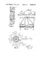
- FIG. 1 is a plan view of the back of a typical panel assembled in accordance with the present invention
- FIG. 2 is an enlarged, end view taken along line 2--2 of FIG.1;
- FIG. 3 is a plan view of the carousel system of the present invention.
- FIG. 4 is a sectional view of the adhesive applicator means of the present invention taken along line 4--4 of FIG. 3.;
- FIG. 5 is an elevational view of a press table of the present invention.
- FIG. 6 is an end view of a press table taken along the line 6--6 of FIG. 5;
- FIG. 7 is a sectional view taken along line 7--7 of FIG. 6;
- FIG. 8 is a sectional view taken along line 8--8 of FIG. 7;
- FIG. 9 is a perspective view, partly broken away, of the press rack of the present invention.
- FIGS. 1 and 2 disclose a panel 10 having a construction typical of a panel which is to be assemblied in accordance with the present invention.
- panel 10 is comprised of a plurality of individual, preformed sections 11 (four shown in FIG. 1) which are aligned end-to-end and spaced in close proximity and then secured together by one or more longitudinal support members 12 (four shown in FIG. 1).
- Support members 12 are positioned across the backs of all sections 11 and glued thereto.
- Cross-supports 13 are secured across supports 12 at spaced intervals to add structural integrity and strength to the assemblied panel 10.
- sections 11 may have a reflective glass surface to reflect and/or focus the sun's rays or may have plurality of photovoltaic cells on the surface thereof if the panel is to be used for the direct conversion of sunlight into electricity.
- System 15 is comprised of a carousel structure 16 which is rotatable mounted on pylon axle 17 which, in turn, is securely anchored in the floor of the assembly area.
- Attached at spaced intervals around the outer periphery 18 of carousel 16 are a plurality of press tables 19.
- twelve tables 19, spaced at 30° intervals have been shown, but it should be understood that more or less tables, spaced at different angular relationships, can be used without departing from the present invention.
- Work station 20 is comprised of conveyor 22 onto which section 11(e.g. 4 foot by 4 foot reflective glass or photovoltaic sections) are loaded.
- section 11 e.g. 4 foot by 4 foot reflective glass or photovoltaic sections
- Each section 11 is manually or otherwise positioned, face down, on the rear of conveyor 22 and are properly spaced, one from the other, as conveyor 22 slowly moves the sections toward table 19.
- adhesive applicator means 23 FIGGS. 3 and 4
- nozzles units 24 lay down lines or beads 25 of adhesive onto the backs of section 11.
- each nozzle unit 24 provides two lines 25 of adhesive so a total of eight separate lines 25 are applied onto the back of each section 11 for a purpose described below.
- sections 11 moves through adhesive applicator 23 and reach the forward end of conveyor 22, they are manually or otherwised moved into position onto the table 19 which is substantially aligned with conveyor 22.
- the operation is now at the point where longitudinal supports 12 and cross-supports 13 are ready to be affixed to the backs of sections 11 to form a panel 10. To fully understand how this is accomplished in the present invention, the detail of press table 19 will now be set forth.
- each press table 19 is identical.
- table 19 (FIGS. 5 and 6) is comprised of a frame 30 on which a plurality of milled top plates 31 (four shown) are mounted by adjustable bolts 32.
- Plates 31 are preferably of heavy, stable material (e.g. 3/4 inch thick steel) which has been milled and/or polished to provide an extremely level and smooth surface, a plurality of adjustable jack bolts 32 (only a few shown for clarity) connect the plates 31 to frame 30 and are individually manipulated to adjust the height and to properly level plates 31 with respect to frame 30 and to each other.
- Frame 30 is supported on the floor of the assembly area by wheel means, e.g. casters 34 which are pivotably mounted near the outer end of frame 30 and a set of tandem wheels 3 transversely journaled on frame 30 toward its inner end.
- wheel means e.g. casters 34 which are pivotably mounted near the outer end of frame 30 and a set of tandem wheels 3 transversely journaled on frame 30 toward its inner end.
- the outer surfaces 36 of wheels 35 are slightly tapered inwardly to allow the wheels to follow a circular "footprint" when table 19 is rotated to a new position about pivot point 17.
- the taper of wheels 35 prevents "scuffing" or sliding of these wheels as they roll across the assembly area floor as the tables 19 are moved to a different position around pylon 17.
- each table 19 further include a power means 37, e.g. electric motor or equivalent, which is mounted on frame 30 and operably coupled to wheels 35 to drive same upon command.
- a power means 37 e.g. electric motor or equivalent
- motor 37 rotates wheels 35 to move table 19a in a circular direction about pylon 17
- carousel structure 16 will likewise be rotated thereby causing all tables 19 to rotate to their next position about pylon 17.
- Frame 30 of each table 19 is affixed to carousel structure by pins 19b (FIG. 3) which are positioned through openings 19c (FIG. 5) on the frame.
- Rack 39 comprises a frame support structure 40 which, as illustrated, is comprised of a plurality of longitudinal struts 41 (four shown) which are joined together by cross-struts 42.
- Power means 40a (pneumatic or hydraulic cylinder or equivalent) is coupled between rack 39 and frame 30 to rotate rack 39 on command about pivot 38 to raise rack 39 to an "up" position away from frame 30 and a “down" position.
- rack 39 When in the "down" position, rack 39 will be substantially parallel to the surface of plates 31 and will be properly spaced there from. If the thickness of sections 11 vary, the spacing of rack 39 from plates 31 can be adjusted by jack bolts 38a (FIG. 5) to raise or lower pivot 38.
- Counterweight 40b is provided at the inner end of rack 39 to at least partially equalize the weight of rack 39 on either side of pivot 38 which aids in moving rack 39 between its up and down positions.
- press bars 43 Carried at spaced points along frame support structure 40 are one or more press bars 43 (four shown in FIG. 5). Each press bar 43 is mounted on press rack 39 for limited movement away from and towards frame support structure 40. Two different means are illustrated for mounting press bars 43 to provide the desired limited movement.
- the first of these means 4 (FIGS. 5 and 7) is comprised of a housing which is bolted or otherwise secured to outer struts 41 adjacent a press bar 43.
- Pins 46 are affixed to the upper surface of press bar 43 near the outer ends thereof and are slidably received through openings 47 in respective housings 45.
- a return spring 48 is positioned onto that portion of pin 46 that extends above housing 45 and is held thereon by retainer nut 49 or equivalent.
- the second means 44a used to moveably mount press bar 43 to press rack 39 is comprised of a pin 46a affixed to bar 43 near the center thereof and which is received through an opening 47a in cross-strut 42.
- Return spring 48a is positioned on pin 46a above strut 42 and is held in place by retainer 49a.
- Each press bar 43 has one or more recesses 50 (four shown) in the lower surface thereof. Recesses 50 are spaced on each bar 43 so that each recess on a particular bar is in logitudinal alignment with the recesses in the same relative position on all of the other said press bars.
- Each set of aligned recesses on press bars 43 form a channel into which one of metallic support members 12 of panel 10 is adapted to be positioned.
- Support member 12 is releasably held in its respective channel by a releasably securing means which, in turn, is comprised of permanent magnets 51 which are positioned in slots 52 within recesses 50.
- Means 53 is comprised of one or more L-shaped members 54 which are bolted or otherwise secured to the top of press bar 43 and which have a permanent magnet 55 thereon.
- each boot 56 is positioned between a respective strut 41 and each of press bars 43 and is additionally supported along its length by straps 57 (FIGS. 5 and 7) which, in turn, are bolted or otherwise secured to the strut 41.
- a pad 58 of rubber or similar elastic material is positioned within each strap 57 between the strap and its respective boot.
- one or more guy wires 60 are run from mast 61 on frame support structure 40 to various cross-struts 42. Further, cooperating, releasable latch means 62, 63 are provided on frame 30 and press rack 39 to lock the press rack 39 in its down position.
- Sections 11 are positioned face down on conveyor 22 in their desired, aligned relationship.
- preformed sections 11 may be of various constructions (e.g. reflective glass sections, photovoltaic array sections, etc.) al long as they have a substrate (back) capable of having support member glued thereto.
- Preformed sections 11 are passed along conveyor 22 and through adhesive applicator 23 where adhesive is applied to the backs of all sections 11.
- applicator means 23 applies eight lines of adhesive to each section 11. These lines of adhesive 25 (FIG. 4) are carefully spaced so that they will underlie the parallel surfaces 12a (FIG. 7) of the four longitudinal supports 12 when he supports are positioned across the backs of sections 11.
- sections 11 pass through applicator means 23 and reach the front of conveyor 22, they are manually or otherwise transferred to the table 19 which is then in alignment with conveyor 22.
- table 19 which is then in alignment with conveyor 22.
- four of the 4 foot by 4 foot preformed sections 11 with the lines of adhesive on the backs thereof are positioned, face down, onto plates 31 against stops 31a and are properly aligned onto the plates 31.
- One or more cross-supports 13 e.g. aluminized steel having adhesive applied to the inner surfaces 13a (FIG. 2) thereof are positioned into respective securing means 53 on cross bars 43 and are releasably held therein by magnets 55.
- One or more longitudinal supports 12 e.g. 16 foot long, aluminized steel "hat sections" are positioned within their respective channels formed by aligned recesses 50 in press bars 43 and are releasably held therein by magnets 51.
- preformed and prespaced holes 71 (FIG. 7) in supports 12 are aligned with index pins 70 which, in turn, are secured in recesses 50 on press bars 43.
- boots 56 Compressed air is then supplied to boots 56 through plenum 56a (FIG. 5) to inflate all of the boots simultaneously.
- the boots inflate, they force press bars 43 and, hence, supports 12 downward into firm contact with the adhesive on sections 11.
- pads 58 in straps 57 are pressed downward against supports by inflated boots 56 to provide additional pressure along the lengths of supports 12.
- boots 56 apply pressure against cross-supports 13 to force the adhesive-coated surfaces 13a thereof into firm contact with supports 12 to thereby bond the two together.
- a sensor 75 e.g. electric eye, (FIG. 5) is positioned at any one of the stations of carousel 16 to sense a reflective surface 76 (one on each table 19) to automatically stop motor 37 when tables 19 have been stepped to their next adjacent location about pylon 17.
- the total time it takes to load (e.g. 3 minutes) each table 19 at work stations 20 and to step it around through each stop to work station 21 is preferably equal to or is greater than the time it takes the adhesive being used to cure (e.g. 30 minutes).
- panel 10 in a table will be ready for removal by the time that table has been stepped around to work station 21, air is exhausted from boots 56 and springs 48, 48a move press bars 43 upward which aids in deflating boots 56.
- Latch means 62, 63 are released and power cylinder 40a is actuated to raise rack 39 to its up position.
- the weight of panel 10 is such that it overcomes the holding power of magnets 51, 55 so panel 10 will remain on plates 31 as rack 39 is raised.
- the panel is then manually or otherwise removed from table 19 and placed on conveyor 21a which carries the assembled panel 10 away from 19.
- the completed panel is then removed from the rear of conveyor 21a for further handling.
- the adhesive can be applied directly to the supports 12 instead of/or in addition to the adhesive being applied to the backs of sections 11 and/or to the cross-supports 13 as described.
Landscapes
- Engineering & Computer Science (AREA)
- Mechanical Engineering (AREA)
- Photovoltaic Devices (AREA)
Abstract
Description
Claims (9)
Priority Applications (1)
| Application Number | Priority Date | Filing Date | Title |
|---|---|---|---|
| US06/613,853 US4640734A (en) | 1984-05-24 | 1984-05-24 | Method and apparatus for assembling large panels |
Applications Claiming Priority (1)
| Application Number | Priority Date | Filing Date | Title |
|---|---|---|---|
| US06/613,853 US4640734A (en) | 1984-05-24 | 1984-05-24 | Method and apparatus for assembling large panels |
Publications (1)
| Publication Number | Publication Date |
|---|---|
| US4640734A true US4640734A (en) | 1987-02-03 |
Family
ID=24458939
Family Applications (1)
| Application Number | Title | Priority Date | Filing Date |
|---|---|---|---|
| US06/613,853 Expired - Fee Related US4640734A (en) | 1984-05-24 | 1984-05-24 | Method and apparatus for assembling large panels |
Country Status (1)
| Country | Link |
|---|---|
| US (1) | US4640734A (en) |
Cited By (23)
| Publication number | Priority date | Publication date | Assignee | Title |
|---|---|---|---|---|
| US5409341A (en) * | 1992-12-09 | 1995-04-25 | Kolbus Gmbh & Co., Kg | Book cover assembly apparatus |
| US5425838A (en) * | 1991-07-08 | 1995-06-20 | Advantek, Inc. | Microchip storage tape and cover therefor |
| US5885411A (en) * | 1995-04-10 | 1999-03-23 | Latter; Melvin R. | Modular sealing machine |
| US20020189754A1 (en) * | 2001-04-30 | 2002-12-19 | Hill David A. | System and method for forming wood products |
| US20110012264A1 (en) * | 2009-07-20 | 2011-01-20 | Ryan Linderman | Optoelectronic device with heat spreader unit |
| US20110120524A1 (en) * | 2009-11-20 | 2011-05-26 | Sunpower Corporation | Device and method for solar power generation |
| US20110132431A1 (en) * | 2009-12-08 | 2011-06-09 | Ryan Linderman | Optoelectronic device with bypass diode |
| US20120279662A1 (en) * | 2009-12-18 | 2012-11-08 | Airbus Operations Gmbh | Apparatus for the production of an aircraft fuselage shell consisting of a fibre composite |
| US8336539B2 (en) | 2010-08-03 | 2012-12-25 | Sunpower Corporation | Opposing row linear concentrator architecture |
| US8528366B2 (en) | 2011-12-22 | 2013-09-10 | Sunpower Corporation | Heat-regulating glass bending apparatus and method |
| US8563849B2 (en) | 2010-08-03 | 2013-10-22 | Sunpower Corporation | Diode and heat spreader for solar module |
| US8604404B1 (en) | 2010-07-01 | 2013-12-10 | Sunpower Corporation | Thermal tracking for solar systems |
| US8636198B1 (en) | 2012-09-28 | 2014-01-28 | Sunpower Corporation | Methods and structures for forming and improving solder joint thickness and planarity control features for solar cells |
| US8796535B2 (en) | 2011-09-30 | 2014-08-05 | Sunpower Corporation | Thermal tracking for solar systems |
| US8839784B2 (en) | 2010-12-22 | 2014-09-23 | Sunpower Corporation | Locating connectors and methods for mounting solar hardware |
| US8893713B2 (en) | 2010-12-22 | 2014-11-25 | Sunpower Corporation | Locating connectors and methods for mounting solar hardware |
| US20150033672A1 (en) * | 2013-07-31 | 2015-02-05 | Goodrich Corporation | Evacuation system packing device |
| US9035168B2 (en) | 2011-12-21 | 2015-05-19 | Sunpower Corporation | Support for solar energy collectors |
| US9038421B2 (en) | 2011-07-01 | 2015-05-26 | Sunpower Corporation | Glass-bending apparatus and method |
| US9246037B2 (en) | 2010-12-03 | 2016-01-26 | Sunpower Corporation | Folded fin heat sink |
| US9397611B2 (en) | 2012-03-27 | 2016-07-19 | Sunpower Corporation | Photovoltaic systems with local maximum power point tracking prevention and methods for operating same |
| US9897346B2 (en) | 2010-08-03 | 2018-02-20 | Sunpower Corporation | Opposing row linear concentrator architecture |
| US9911882B2 (en) | 2010-06-24 | 2018-03-06 | Sunpower Corporation | Passive flow accelerator |
Citations (10)
| Publication number | Priority date | Publication date | Assignee | Title |
|---|---|---|---|---|
| US1657227A (en) * | 1927-03-10 | 1928-01-24 | Pittsburgh Plate Glass Co | Apparatus for making composite glass |
| US1754853A (en) * | 1926-12-17 | 1930-04-15 | Pittsburgh Plate Glass Co | Apparatus for making composite glass |
| US2337250A (en) * | 1942-08-17 | 1943-12-21 | Edward J Klassen | Gluing press |
| US2713379A (en) * | 1952-11-25 | 1955-07-19 | Firestone Tire & Rubber Co | Magnetic device for clamping overlapping parts during adhesive bonding |
| US3355209A (en) * | 1965-05-10 | 1967-11-28 | Magnetic Devices Inc | Material handling device |
| US3771438A (en) * | 1971-10-12 | 1973-11-13 | L Radakovich | Means for molding |
| US3808968A (en) * | 1972-02-17 | 1974-05-07 | Minet Ets | Press-devices |
| US3971688A (en) * | 1974-12-20 | 1976-07-27 | Fruehauf Corporation | Method of making an elongate, transversely reinforced metal sheet |
| US4220491A (en) * | 1978-10-19 | 1980-09-02 | Ppg Industries, Inc. | Method for forming an accurately assembled laminate utilizing a vacuum holding press |
| US4468848A (en) * | 1982-03-08 | 1984-09-04 | Atlantic Richfield Company | Method of making combination curved-lightweight mirror module |
-
1984
- 1984-05-24 US US06/613,853 patent/US4640734A/en not_active Expired - Fee Related
Patent Citations (10)
| Publication number | Priority date | Publication date | Assignee | Title |
|---|---|---|---|---|
| US1754853A (en) * | 1926-12-17 | 1930-04-15 | Pittsburgh Plate Glass Co | Apparatus for making composite glass |
| US1657227A (en) * | 1927-03-10 | 1928-01-24 | Pittsburgh Plate Glass Co | Apparatus for making composite glass |
| US2337250A (en) * | 1942-08-17 | 1943-12-21 | Edward J Klassen | Gluing press |
| US2713379A (en) * | 1952-11-25 | 1955-07-19 | Firestone Tire & Rubber Co | Magnetic device for clamping overlapping parts during adhesive bonding |
| US3355209A (en) * | 1965-05-10 | 1967-11-28 | Magnetic Devices Inc | Material handling device |
| US3771438A (en) * | 1971-10-12 | 1973-11-13 | L Radakovich | Means for molding |
| US3808968A (en) * | 1972-02-17 | 1974-05-07 | Minet Ets | Press-devices |
| US3971688A (en) * | 1974-12-20 | 1976-07-27 | Fruehauf Corporation | Method of making an elongate, transversely reinforced metal sheet |
| US4220491A (en) * | 1978-10-19 | 1980-09-02 | Ppg Industries, Inc. | Method for forming an accurately assembled laminate utilizing a vacuum holding press |
| US4468848A (en) * | 1982-03-08 | 1984-09-04 | Atlantic Richfield Company | Method of making combination curved-lightweight mirror module |
Cited By (41)
| Publication number | Priority date | Publication date | Assignee | Title |
|---|---|---|---|---|
| US5425838A (en) * | 1991-07-08 | 1995-06-20 | Advantek, Inc. | Microchip storage tape and cover therefor |
| US5409341A (en) * | 1992-12-09 | 1995-04-25 | Kolbus Gmbh & Co., Kg | Book cover assembly apparatus |
| US5885411A (en) * | 1995-04-10 | 1999-03-23 | Latter; Melvin R. | Modular sealing machine |
| US20020189754A1 (en) * | 2001-04-30 | 2002-12-19 | Hill David A. | System and method for forming wood products |
| US20070221311A1 (en) * | 2001-04-30 | 2007-09-27 | Hill David A | System and method for forming wood products |
| US20110012264A1 (en) * | 2009-07-20 | 2011-01-20 | Ryan Linderman | Optoelectronic device with heat spreader unit |
| US8860162B2 (en) | 2009-07-20 | 2014-10-14 | Sunpower Corporation | Optoelectronic device with heat spreader unit |
| US8530990B2 (en) | 2009-07-20 | 2013-09-10 | Sunpower Corporation | Optoelectronic device with heat spreader unit |
| US9466748B2 (en) | 2009-07-20 | 2016-10-11 | Sunpower Corporation | Optoelectronic device with heat spreader unit |
| US8304644B2 (en) | 2009-11-20 | 2012-11-06 | Sunpower Corporation | Device and method for solar power generation |
| US20110120524A1 (en) * | 2009-11-20 | 2011-05-26 | Sunpower Corporation | Device and method for solar power generation |
| US8546681B2 (en) | 2009-11-20 | 2013-10-01 | Sunpower Corporation | Device and method for solar power generation |
| US8946541B2 (en) | 2009-11-20 | 2015-02-03 | Sunpower Corporation | Device and method for solar power generation |
| US9252314B2 (en) | 2009-11-20 | 2016-02-02 | Sunpower Corporation | Device and method for solar power generation |
| US20110132431A1 (en) * | 2009-12-08 | 2011-06-09 | Ryan Linderman | Optoelectronic device with bypass diode |
| US8809671B2 (en) | 2009-12-08 | 2014-08-19 | Sunpower Corporation | Optoelectronic device with bypass diode |
| US8746315B2 (en) * | 2009-12-18 | 2014-06-10 | Airbus Operations Gmbh | Apparatus for the production of an aircraft fuselage shell consisting of a fibre composite |
| US20120279662A1 (en) * | 2009-12-18 | 2012-11-08 | Airbus Operations Gmbh | Apparatus for the production of an aircraft fuselage shell consisting of a fibre composite |
| US9911882B2 (en) | 2010-06-24 | 2018-03-06 | Sunpower Corporation | Passive flow accelerator |
| US8604404B1 (en) | 2010-07-01 | 2013-12-10 | Sunpower Corporation | Thermal tracking for solar systems |
| US9281431B2 (en) | 2010-07-01 | 2016-03-08 | Sunpower Corporation | Thermal tracking for solar systems |
| US8336539B2 (en) | 2010-08-03 | 2012-12-25 | Sunpower Corporation | Opposing row linear concentrator architecture |
| US8563849B2 (en) | 2010-08-03 | 2013-10-22 | Sunpower Corporation | Diode and heat spreader for solar module |
| US9897346B2 (en) | 2010-08-03 | 2018-02-20 | Sunpower Corporation | Opposing row linear concentrator architecture |
| US9322963B2 (en) | 2010-08-03 | 2016-04-26 | Sunpower Corporation | Opposing row linear concentrator architecture |
| US9685573B2 (en) | 2010-08-03 | 2017-06-20 | Sunpower Corporation | Diode and heat spreader for solar module |
| US8584667B2 (en) | 2010-08-03 | 2013-11-19 | Sunpower Corporation | Opposing row linear concentrator architecture |
| US9246037B2 (en) | 2010-12-03 | 2016-01-26 | Sunpower Corporation | Folded fin heat sink |
| US9746655B2 (en) | 2010-12-22 | 2017-08-29 | Sunpower Corporation | Locating connectors and methods for mounting solar hardware |
| US8893713B2 (en) | 2010-12-22 | 2014-11-25 | Sunpower Corporation | Locating connectors and methods for mounting solar hardware |
| US8839784B2 (en) | 2010-12-22 | 2014-09-23 | Sunpower Corporation | Locating connectors and methods for mounting solar hardware |
| US9038421B2 (en) | 2011-07-01 | 2015-05-26 | Sunpower Corporation | Glass-bending apparatus and method |
| US9249044B2 (en) | 2011-07-01 | 2016-02-02 | Sunpower Corporation | Glass bending method and apparatus |
| US8796535B2 (en) | 2011-09-30 | 2014-08-05 | Sunpower Corporation | Thermal tracking for solar systems |
| US9035168B2 (en) | 2011-12-21 | 2015-05-19 | Sunpower Corporation | Support for solar energy collectors |
| US9455664B2 (en) | 2011-12-21 | 2016-09-27 | Sunpower Corporation | Support for solar energy collectors |
| US8528366B2 (en) | 2011-12-22 | 2013-09-10 | Sunpower Corporation | Heat-regulating glass bending apparatus and method |
| US9397611B2 (en) | 2012-03-27 | 2016-07-19 | Sunpower Corporation | Photovoltaic systems with local maximum power point tracking prevention and methods for operating same |
| US8636198B1 (en) | 2012-09-28 | 2014-01-28 | Sunpower Corporation | Methods and structures for forming and improving solder joint thickness and planarity control features for solar cells |
| US8991682B2 (en) | 2012-09-28 | 2015-03-31 | Sunpower Corporation | Methods and structures for forming and improving solder joint thickness and planarity control features for solar cells |
| US20150033672A1 (en) * | 2013-07-31 | 2015-02-05 | Goodrich Corporation | Evacuation system packing device |
Similar Documents
| Publication | Publication Date | Title |
|---|---|---|
| US4640734A (en) | Method and apparatus for assembling large panels | |
| US4980013A (en) | Apparatus for forming and curing an I-section workpiece | |
| JP5046955B2 (en) | Integrated barrel assembly cart | |
| ATE57494T1 (en) | TIRE CURING PLANT. | |
| US4259776A (en) | Method of assembly of airship hull | |
| CN111055501A (en) | Pressurizing tool single body, web assembling tool, blade forming method and blade | |
| CN112338847A (en) | Lifting, positioning, supporting and clamping tool | |
| CN208882266U (en) | A kind of speaker wrapping automatic production equipment | |
| CN222463984U (en) | Auxiliary frame for electric power construction | |
| US4870858A (en) | Tire testing machine | |
| CA2444181A1 (en) | Manufacture of a filtering screen | |
| CN217837533U (en) | Mobile sand pressure testing device | |
| CN110653899A (en) | Glue and plank compression equipment | |
| CN116815329A (en) | Stick-sticking automatic centering equipment | |
| CN223732506U (en) | Fixing frame for filling auxiliary catalyst | |
| CN222757821U (en) | A steel structure material transfer device | |
| CN224145980U (en) | Hillside land photovoltaic material conveyer | |
| CN218786007U (en) | Wind-powered electricity generation blade transports frock | |
| CN215438626U (en) | A mounting fixture for unilateral truss of liftable | |
| CN218595409U (en) | Conveying mechanism for automatic production of toys | |
| CN222973445U (en) | A transport device for photovoltaic equipment manufacturing | |
| CN219728262U (en) | Photovoltaic module handling device | |
| CN215659372U (en) | Grinding device is used in production of wood system tray with clamping function | |
| CN218496627U (en) | Loft stair step testing tool | |
| CN212555402U (en) | PTFE film laminating device |
Legal Events
| Date | Code | Title | Description |
|---|---|---|---|
| AS | Assignment |
Owner name: ATLANTIC RICHFIELD COMPANY, LOS ANELES, CA CORP OF Free format text: ASSIGNMENT OF ASSIGNORS INTEREST.;ASSIGNORS:ROBERTS, ERNEST E.;HANSEL, PAUL H.;HUDGENS, WILLIAM O.;REEL/FRAME:004270/0345;SIGNING DATES FROM 19840523 TO 19840524 |
|
| FEPP | Fee payment procedure |
Free format text: PAYOR NUMBER ASSIGNED (ORIGINAL EVENT CODE: ASPN); ENTITY STATUS OF PATENT OWNER: LARGE ENTITY |
|
| AS | Assignment |
Owner name: ARCO SOLAR, INC., A CORP. OF DE., CALIFORNIA Free format text: ASSIGNMENT OF ASSIGNORS INTEREST.;ASSIGNOR:ATLANTIC RICHFIELD COMPANY, 515 SOUTH FLOWER ST., LOS ANGELES, CA. 90071, A CORP. OF DE.;REEL/FRAME:005268/0539 Effective date: 19900212 |
|
| FPAY | Fee payment |
Year of fee payment: 4 |
|
| AS | Assignment |
Owner name: SIEMENS SOLAR INDUSTRIES, L.P. Free format text: MERGER;ASSIGNOR:ARCO SOLAR, INC.;REEL/FRAME:005657/0516 Effective date: 19900228 |
|
| FEPP | Fee payment procedure |
Free format text: PAYOR NUMBER ASSIGNED (ORIGINAL EVENT CODE: ASPN); ENTITY STATUS OF PATENT OWNER: LARGE ENTITY Free format text: PAYER NUMBER DE-ASSIGNED (ORIGINAL EVENT CODE: RMPN); ENTITY STATUS OF PATENT OWNER: LARGE ENTITY |
|
| REMI | Maintenance fee reminder mailed | ||
| LAPS | Lapse for failure to pay maintenance fees | ||
| FP | Lapsed due to failure to pay maintenance fee |
Effective date: 19950208 |
|
| STCH | Information on status: patent discontinuation |
Free format text: PATENT EXPIRED DUE TO NONPAYMENT OF MAINTENANCE FEES UNDER 37 CFR 1.362 |