US463596A - Tucky - Google Patents
Tucky Download PDFInfo
- Publication number
- US463596A US463596A US463596DA US463596A US 463596 A US463596 A US 463596A US 463596D A US463596D A US 463596DA US 463596 A US463596 A US 463596A
- Authority
- US
- United States
- Prior art keywords
- casing
- shaft
- sleeve
- wheel
- pinion
- Prior art date
- Legal status (The legal status is an assumption and is not a legal conclusion. Google has not performed a legal analysis and makes no representation as to the accuracy of the status listed.)
- Expired - Lifetime
Links
- 238000010276 construction Methods 0.000 description 2
- 239000002184 metal Substances 0.000 description 1
- 230000013707 sensory perception of sound Effects 0.000 description 1
- 238000009958 sewing Methods 0.000 description 1
Images

Classifications
-
- F—MECHANICAL ENGINEERING; LIGHTING; HEATING; WEAPONS; BLASTING
- F03—MACHINES OR ENGINES FOR LIQUIDS; WIND, SPRING, OR WEIGHT MOTORS; PRODUCING MECHANICAL POWER OR A REACTIVE PROPULSIVE THRUST, NOT OTHERWISE PROVIDED FOR
- F03G—SPRING, WEIGHT, INERTIA OR LIKE MOTORS; MECHANICAL-POWER PRODUCING DEVICES OR MECHANISMS, NOT OTHERWISE PROVIDED FOR OR USING ENERGY SOURCES NOT OTHERWISE PROVIDED FOR
- F03G1/00—Spring motors
- F03G1/02—Spring motors characterised by shape or material of spring, e.g. helical, spiral, coil
- F03G1/022—Spring motors characterised by shape or material of spring, e.g. helical, spiral, coil using spiral springs
-
- F—MECHANICAL ENGINEERING; LIGHTING; HEATING; WEAPONS; BLASTING
- F03—MACHINES OR ENGINES FOR LIQUIDS; WIND, SPRING, OR WEIGHT MOTORS; PRODUCING MECHANICAL POWER OR A REACTIVE PROPULSIVE THRUST, NOT OTHERWISE PROVIDED FOR
- F03G—SPRING, WEIGHT, INERTIA OR LIKE MOTORS; MECHANICAL-POWER PRODUCING DEVICES OR MECHANISMS, NOT OTHERWISE PROVIDED FOR OR USING ENERGY SOURCES NOT OTHERWISE PROVIDED FOR
- F03G1/00—Spring motors
Definitions
- A represents the stand of a sewing-machine, (shown in dotted lines,) and B the table thereof.
- tableB Upon tableB is mounted a drum or casing 0, held in place by means of clamp C and set-screw a, the clamp passing over one foot of the drum.
- this casing At each end this casing is provided with strips D, which are placed at rightangles to each other, crossing at or about the center of the casing and forrhing bearings for a shaftE.
- F represents a sleeve which fits loosely upon shaft E, and to which are keyed a ratchet G and pinion H.
- Pinion H is arranged to mesh with a second pinion K, mounted upon a shaft, which has hearings in the upper vertical strip D and projecting, at one end sufficiently to receive a crank-handle L.
- e also provide a pawl X, which may be mounted at any suitable point on the casing, it being arranged to engage the ratchet G, before re ferred to, and prevent such ratchet and the sleeve to which it is keyed revolving in more than one direction.
- a pawl X which may be mounted at any suitable point on the casing, it being arranged to engage the ratchet G, before re ferred to, and prevent such ratchet and the sleeve to which it is keyed revolving in more than one direction.
- A represents an arm pivoted to one of the strips D, and provided at one end with a brake-block arranged to engage the frictionpulley R, the opposite end of this rod being preferably hook-shaped to receive a rod B, which is provided at its lower end with a loop or stirrup to receive the foot of the operator.
- C represents a rack secured to casing C, and with which the pivoted brake-rod A engages.
- Vhat we claim is In a sewing-machine motor, the combination of a drum or casing, the vertical and horizontal strips at each end of said casing crossing each other, as illustrated, the transverse shaft journaled in the said strips, a large gear-Wheel fixed on said shaft, a sleeve loosely mounted on the shaft,aratchet-wheel fixed on said'sleeve, a pinion also fixed on the sleeve, a pawl pivotally connected to one of the horizontal strips of the casing and adapted to engage the ratchet-wheel of the sleeve, a pinion fixed on a shaft journaled in an upright stripof the casing and adapted to engage the pinion of the sleeve, acrank fixed on the end of said shaft, a pinion fixed on a shaft carrying a band-pulley and engagingthe large gear in the casing, a friction-wheel fixed on the shaft carrying the latter pinion, a coiled metal spring having one of its ends connected to the
Landscapes
- Engineering & Computer Science (AREA)
- Chemical & Material Sciences (AREA)
- Combustion & Propulsion (AREA)
- Mechanical Engineering (AREA)
- General Engineering & Computer Science (AREA)
- Sewing Machines And Sewing (AREA)
Description
2 sn ets -sheeu 1.
(No Model.)
W, H. CLAYTON 8?; R. P. DUNCAN. 8 MOTORFOR SEWING MACHINES. No. 463,696. Patented Nov. 17, 1-891.
Wiiwwaao v Q N ms ucmua PETERS c0., flmxmirrmz, WASHINGTON, n. c.
(No Model.) 2 Sheets-Sheet 2.
W-. H. CLAYTON 8: R. P. DUNCAN. MOTOR FOR SEWING MAGHINES.
No. 463,596. Patented N0v.'17, 1891.
)2, JV j? T 6% WE'z ne s fill/iZ/OK? c%%2@ J Z3 m: cams PETERS co., PHOTO-NWO" wnmm-rou, 04 c.
Nrrnn STATES \VILLIAM H. CLAYTON AND ROBERT P.
TUCKY; PLACE.
ATENT OFFICE.
DUNCAN, OF LOUISVILLE, KEN- MOTOR FOR SEW|NG=MACH|NES.
SPECIFICATION forming part of Letters Patent No. 463,596, dated November 17, 1891.
Application filed October 23, 1889. Serial No. 327,878. (No model.)
which it appertains to make and use the same;
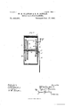
Our invention relates to improvements in sewing-machine motors; and its construction and manner of operating will be understood from the following description, taken in connection with the accompanying drawings, in which- Figure 1 is an elevation of our improved motor mounted in a position for use, and Fig. 2 is a vertical diametrical transverse section of the drum casing and gearing, &c., therein.
In the drawings, A represents the stand of a sewing-machine, (shown in dotted lines,) and B the table thereof. Upon tableB is mounted a drum or casing 0, held in place by means of clamp C and set-screw a, the clamp passing over one foot of the drum. At each end this casing is provided with strips D, which are placed at rightangles to each other, crossing at or about the center of the casing and forrhing bearings for a shaftE.
F represents a sleeve which fits loosely upon shaft E, and to which are keyed a ratchet G and pinion H. Pinion H is arranged to mesh with a second pinion K, mounted upon a shaft, which has hearings in the upper vertical strip D and projecting, at one end sufficiently to receive a crank-handle L.
By means of the line of gearing described it will be seen that when the handle L is turned the sleeve F will be revolved. To this sleeve one end of a coil-spring M is secured, the other end of such spring being secured to a large gear-wheel N, which is journaled upon the shaft E and meshes with a pinion O, which latter is mounted upon a shaft P, mounted at the point shown in the drawings, this shaft also carrying a friction-pulley R and belt-wheel S. A belt '1 is passed around wheel S and around belt-wheel W, mounted on the driving-shaft of the machine. e also provide a pawl X, which may be mounted at any suitable point on the casing, it being arranged to engage the ratchet G, before re ferred to, and prevent such ratchet and the sleeve to which it is keyed revolving in more than one direction.
A represents an arm pivoted to one of the strips D, and provided at one end with a brake-block arranged to engage the frictionpulley R, the opposite end of this rod being preferably hook-shaped to receive a rod B, which is provided at its lower end with a loop or stirrup to receive the foot of the operator.
C represents a rack secured to casing C, and with which the pivoted brake-rod A engages.
By the construction and arrangement of parts as described it will be readily seen that the driving-spring of our improved motor may be wound up while the motor is in operation.
Vhat we claim is In a sewing-machine motor, the combination of a drum or casing, the vertical and horizontal strips at each end of said casing crossing each other, as illustrated, the transverse shaft journaled in the said strips, a large gear-Wheel fixed on said shaft, a sleeve loosely mounted on the shaft,aratchet-wheel fixed on said'sleeve, a pinion also fixed on the sleeve, a pawl pivotally connected to one of the horizontal strips of the casing and adapted to engage the ratchet-wheel of the sleeve, a pinion fixed on a shaft journaled in an upright stripof the casing and adapted to engage the pinion of the sleeve, acrank fixed on the end of said shaft, a pinion fixed on a shaft carrying a band-pulley and engagingthe large gear in the casing, a friction-wheel fixed on the shaft carrying the latter pinion, a coiled metal spring having one of its ends connected to the loosely mounted sleeve and its other end connected to the large gear-wheel in the casing, a lever fulcrumed on one of the upright strips of the casing and provided at its forward end with a dished or curvilinear portion adapted In testimony whereof we affixoursignatures to engage the friction-wheel on the end of the in presence of two witnesses.
shaft carrying the band-pulley, and a depend- \VILLIAM II. CLAYTON. ing arm loosely connected to the opposite end ROBERT P. DUNCAN. of said lever and provided with a stirrup at Witnesses:
its lower end, all adapted to operate substan- CHAS. G. HULSEWEDE,
tially as specified. 1 JOHN T. CASEBY.
Publications (1)
| Publication Number | Publication Date |
|---|---|
| US463596A true US463596A (en) | 1891-11-17 |
Family
ID=2532468
Family Applications (1)
| Application Number | Title | Priority Date | Filing Date |
|---|---|---|---|
| US463596D Expired - Lifetime US463596A (en) | Tucky |
Country Status (1)
| Country | Link |
|---|---|
| US (1) | US463596A (en) |
-
0
- US US463596D patent/US463596A/en not_active Expired - Lifetime
Similar Documents
| Publication | Publication Date | Title |
|---|---|---|
| US463596A (en) | Tucky | |
| US444907A (en) | Speing motoe | |
| US277733A (en) | huckins | |
| US575050A (en) | Half to james p | |
| US485487A (en) | Half to egbert b | |
| US297399A (en) | Spring-motor | |
| US643994A (en) | Stop mechanism for wire-coiling machines. | |
| US264767A (en) | Anatole exupere equip | |
| US156161A (en) | Improvement in sewing-machine motors | |
| US288620A (en) | Sewing-machine motor | |
| US672089A (en) | Spring-motor. | |
| US461903A (en) | cameron | |
| US588973A (en) | Operating mechanism for sewing or other machines | |
| US243435A (en) | Hugh duffey | |
| US164439A (en) | Improvement in motors for sewing-machines | |
| US346428A (en) | Albert c | |
| US454991A (en) | Stopping mechanism for twine-balling machines | |
| US494203A (en) | Ephraim herrington | |
| US229113A (en) | Spring-motor | |
| USRE5038E (en) | Improvement in motors for sewing-machines | |
| US332517A (en) | frank haeeell | |
| US710459A (en) | Twisting and winding machine. | |
| US469077A (en) | Gaetano caspani | |
| US744295A (en) | Spring-motor. | |
| US293624A (en) | Mechanical motor |