US463592A - Leather-shaving machine - Google Patents
Leather-shaving machine Download PDFInfo
- Publication number
- US463592A US463592A US463592DA US463592A US 463592 A US463592 A US 463592A US 463592D A US463592D A US 463592DA US 463592 A US463592 A US 463592A
- Authority
- US
- United States
- Prior art keywords
- knife
- frame
- holder
- carried
- shaving
- Prior art date
- Legal status (The legal status is an assumption and is not a legal conclusion. Google has not performed a legal analysis and makes no representation as to the accuracy of the status listed.)
- Expired - Lifetime
Links
- 239000010985 leather Substances 0.000 description 18
- 230000007246 mechanism Effects 0.000 description 9
- 239000000463 material Substances 0.000 description 7
- 230000009471 action Effects 0.000 description 4
- 238000010276 construction Methods 0.000 description 3
- 238000005520 cutting process Methods 0.000 description 3
- 238000000034 method Methods 0.000 description 3
- 230000008569 process Effects 0.000 description 3
- 235000015241 bacon Nutrition 0.000 description 2
- 230000008859 change Effects 0.000 description 2
- 230000006872 improvement Effects 0.000 description 2
- 230000008901 benefit Effects 0.000 description 1
- 230000001680 brushing effect Effects 0.000 description 1
- 230000002951 depilatory effect Effects 0.000 description 1
- 239000011521 glass Substances 0.000 description 1
- 230000001788 irregular Effects 0.000 description 1
- 239000011435 rock Substances 0.000 description 1
- 238000006467 substitution reaction Methods 0.000 description 1
- 239000002023 wood Substances 0.000 description 1
Images


Classifications
-
- C—CHEMISTRY; METALLURGY
- C14—SKINS; HIDES; PELTS; LEATHER
- C14B—MECHANICAL TREATMENT OR PROCESSING OF SKINS, HIDES OR LEATHER IN GENERAL; PELT-SHEARING MACHINES; INTESTINE-SPLITTING MACHINES
- C14B1/00—Manufacture of leather; Machines or devices therefor
- C14B1/02—Fleshing, unhairing, samming, stretching-out, setting-out, shaving, splitting, or skiving skins, hides, or leather
- C14B1/04—Fleshing, unhairing, samming, stretching-out, setting-out, shaving, splitting, or skiving skins, hides, or leather using slicking, scraping, or smoothing-out cylinders or blades fixed on supports, e.g. cylinders, in a plane substantially at right angles to the working surface
- C14B1/10—Fleshing, unhairing, samming, stretching-out, setting-out, shaving, splitting, or skiving skins, hides, or leather using slicking, scraping, or smoothing-out cylinders or blades fixed on supports, e.g. cylinders, in a plane substantially at right angles to the working surface in machines with drums with cylindrical, conical, or similar surfaces for supporting the whole working piece
Definitions
- My invention relates to leather-shaving machines; and it consists of certain improvements which are fullyset forth in the following specification and are shown in the accompanying drawings, which form a part thereof.
- Machines have been devisedfor shaving leather, but they have been unsatisfactory, and have not prod need the smooth surface obtained by hand shaving.
- Such machines have usu all y employed rotarycuttin g-knives, which were passed over the surface of the skin, and these rotary cutters produce an irregular or slightly-roughened surface, which is highly objectionable.
- the object of my invention is to accomplish by means of machinery the shaving of the skin in a manner similar to that now accomplished by the hand tools, whereby the gradual and continuous snide cut of the handtool may be made with much greater rapidity and with consequent cheapness.
- a great advantage is also obtained from the employment of a machine over the hand operation, in that the amount or depth of each cut. is uniform, and consequently the skin may be shaved to a perfectly uniform thickness.
- a suitable support or table for the skin to be treated and a shaving-knife which is moved over the table in contact with the surface of the skin.
- the knife-holder is supported in a
- my invention employ a suitable carrier, which is reciprocated in guides to move the knife over the surface of the skin.
- the guiding-frame in which the carrier is guided is lifted by suitable cam mechanism during the backward reciprocation or return of the carrier, and thus the knife is raised clear of the surface of the skin.
- the frame is again lowered or dropped to bring the knife again in contact with the surface of the skin.
- the knife-holder in the carrier diagonally, so that it moves in this diagonal position over the surface of the skin.
- the position of the knife-holder may be shifted after each reciprocation back and forth, so as to throw the knife-frame into the opposite diagonal position.
- the angle of the cut may thus be varied with each operation and great uniformity in the shaved surface of the skin may be obtained in consequence.
- My invention also relates to certain imto the shaving of leather, it may be used for a variety of other purposes'without in any way departing from the principles of the invention.
- leather working it may be used for the purpose of removing the hair from the skin, or for the operation of fleshing or removing the thin covering of flesh after-'ft'h-e depilatory process has been carriedout.
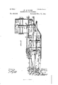
- Figure 1 is a side elevation of my improved leather-shaving machine.
- Fig. 2 is a plan view of the same.
- Fig. 3 is a plan view, on an enlarged scale, of a portion of the machine, showing the knife-holder and carrier, and the trip for shifting the knife- Ioo holder.
- Fig. 4. is an end view of the same, with the knife-holder turned in a straight position.
- Fig. 5 is a longitudinal sectional view of the same on the line m or of Fig. 4.
- Fig. 6 is a longitudinal sectional view on the line y y-of Fig. 4:.
- Fig. 7 is a side elevation of the cam mechanism for operating the knife-holder trip; and
- Fig. 8 is a plan View similar to Fig. 3, showing the knife shifted to the opposite position or angle.
- A is the main frame of the machine.
- B is the table or support for the skin,'which is carried,preferably, in an inclined position upon an upright B.
- the face of this table may be made of glass or other suitable material having a smooth and hard surface.
- B are spring-supports between the table and the upright B, whereby the table B may yield slightly under pressure.
- the tension of these springs B maybe adjusted by means of adj usting-screws b. This adjustment serves also to raise or lower the table.
- B is a clam ping rim or strip of wood or other suitable material upon the upper edge of the table, upon which the skin is clamped during the shaving operation.
- the frame A carries one or more supports A to support the frames 0 C in their lowermost position.
- E is the main driving-shaft of the machine.
- F is a cam carried thereby for actuating the lever D, the end of which is held in contact with the cam by the weight of the frames C O and the devices carried thereby.
- This cam F depresses the free end of the lever D, thereby raising the frames 0 C, which are carried by the lever.
- the lever D may be provided upon its free end with a roller d to reduce the friction between the cam F and lever D.
- G is a reciprocating carrier or frame carried by the guiding-frames G O and movable longitudinally upon guides c c therein.
- I1 is a trip-plate carried by the pivot it above the frame or carrier 0, so as to be moved with the knife-holder II.
- This trip-plate is provided with two pins or stops H located upon relatively opposite sides of the center line of the plate.
- I is a shuttle bar or guide carried by the frames 0 C and arranged above the sliding carrier or frame G.
- the slide or shuttle I is a slide or shuttle movable uponthe shuttle-bar I and guided thereon.
- the slide or shuttle I is adapted to be moved successively into the path of the two pins I1 upon the trip-plate H.
- the bell-crank K is pivoted in an upright A of the main frame A.
- crank-arm L is a crank-arm carried by the shaft 16, and having a pin Z, guided in a slot k in the bell-crank K.
- the crank-arm L rocks the bell-crank K and reciprocates the frame G longitudinally in the guides c c.
- the cam F and the crank-arm L are so arranged with reference one to the other that the former operates to raise the guidingframes (.l C during the upward or return reciprocation of the frame C, and to lower them during the downward or forward reciprocation.
- M are the shaving-knives, of which one or more may be used, as desired. If a single knife is employed it may be connected with the knife-holder II in any convenient manner. To permit a changing of the knife whenever it may be desired without stopping the operation of the entire machine, I prefer to employ the construction shown in the drawings.
- This consists of a knife-clampMQcarried by a shaft m, mounted in the knifeholder I-I. larried by this clamp M are a series of knives M, disconnectably clamped therein by means of the clamping-jaws M and screws M".
- N is a worm-wheel upon the end of the shaft 017.
- worm G is a worm journaled in the knife-holder II and engaging with theworm-wheel N, so that by turning this worm G the shaft m may be rotated to bring a new knife M into opera- IIO tive position.
- a series of knives may be employed and the operative knife may be changed when desired.
- G G are worms upon the frame G, in which is journaled a brush 0 immediately in front of the knife M.
- This brush 0 is preferably carried upon a shaft 0, journaled in vertical slides 0, carried by the arms G and adjustable therein by means of adjusting-screws o and springs 0 E is a rack upon one of the guidingframes 0.
- the knife-holder II is turned into successively opposite angular positions by means of the shuttle or slide 1 which is 'moved successively into position before the different stops 11 H of the trip-plate 11. This trip is preferably operated after each complete back and forth reciprocation of the carrier G.
- P is a bell -crank pivoted to one of the frames 0.
- 1 is a connecting-rod connecting the bellcrank P and the shutter or slide 1.
- J is a connecting-rod connecting the other end of the bell-crank P with a cam-yoke Q.
- R is a crank working within the cam-yoke Q to operate it and carried upon a shaft 4.
- the shaft 1' is operated from the driving-shaft E by means of suitable power-transmitting connections.
- R and R are sprocket-wheels, respectively, upon the shafts r and E.
- Sand S are sprocket-wheels upon the shaft d. Power is transmitted from the sprocketwhe'el R to the sprocket-wheel S and shaft d by means of a chain T, and from the sprocketwheel S to the sprocket-wheel R and the shaft 7' by means of a chain T.
- the shuttle or slide 1 will be operated once upon every back and forth reciprocation of the frame G.
- the cam yoke Q is guided in its movement by means of extensions or arms q working in guides c 0 upon the frame 0. (See Fig. 7.)
- V are respectively the tight and loose driving-pulleys.
- N is a clamp carried by the front
- the operation of the machine is as follows:
- the shaft E may be rotated suificiently to cause the cam F to depress the lever D and raise the frames C O to permit the skin to be operated upon to be placed upon the table B and spread over the smooth surface thereof.
- the machine is now put into operation and when the cam F passes from the end of the lever D theframes O O are dropped, allowing the knife to come in contact with the surface of the skin to be operated upon.
- the skin is clamped in position between the rim B of the table and the clamp N.
- the knife M in con tact with the surface of the skin is in the diagonal position, as heretofore described, to produce the desired snide cut.
- the knife is held in position during the cutting operation by the friction between the knife-holder and movable frame G.
- the rack E and pinion E cause the brush 0 to rotate in the direction in which the knife M moves or away from the moving knife, as is indicated by the arrow in Fig. 1.
- the cam F acts upon the lever D and raises the guiding-arms U 0,1ifting the frame G and moving the knife M from contact with the skin.
- the arms 0 O are held in this raised position by the action of the cam F upon the lever D during the period of time that the frame G is being reciprocated back by the crank-arm L and thebell-crank K, and until it is returned to its highest position, when the cam F passes from the lever D and allows the frames 0 O to drop back with the knife M in contact with the skin.
- the clamp N is raised from the clamping-rim B releasing the skin and permitting its position upon the table 13 to be shifted by the opera tor, so as to present a new surface to the action of the knife.
- the operative knife may be changed by turning the worm G, so as to rotate the clamp M.
- the knives M may be similar to those now employed in hand shaving-tools having a turnedover knife-edge, the character of which is well known'in the art.
- knives of a'difierent character may be used, as the particular work in hand may require. Such a substitution does not involve a departure from my invention.
- a leather-shavingmachine the combination, with a support for the leather, of a frame arranged above said support and provided with guides and fixed against longitudinal movement, cam mechanism to successively raise and lower said frame, a reciprocating knife holder or carrier guided in said frame, and means to reciprocate the knifeholder therein independently of the movement of the frame, whereby the knife-holder is reciprocated in the guides of said frame and the frame is successively raised and lowered during said reciprocation to move the knife-holder to and from the table.
- a supporting-table, guidingframes arranged over said table, cam mechanism to raise and lower said frames, aclamp carried by said frames, a knife-holder and its knife also carried by said frames and free to reciprocate therein, and means to reciprocate said knife-holder in the frames, whereby said clamp and knife are raised and lowered from and to the supporting-table simultaneously with each other with the raising and lowering of the guiding-frames.
- a support for the article to be operated upon a reciprocating knife-holder movable over said support, a knife carried by said knife-holder, and a rotating brush arranged adjacent to and in front of the knife and rotating in the direction of the movement of said knife on a transverse axis to its line of movement.
- a support for the article to be operated upon a reciprocating frame movable over said support, guiding-frames for said reciprocating frame, a knife carried by said reciprocating frame, a brush also carried by said movable frame and arranged in front of and adjacent to said knife, a rack carried by said guiding-frame, and a pinion gearing with said rack carried by said brush, whereby the brush is rotated in the direction of the travel of said reciprocating frame and knife during, its reciprocations.
- a support for the article to be operated upon guiding-frames arranged over said support, a reciprocating frame guided in said guiding-frames, means to reciprocate said reciprocating frame, a knife-holder pivoted to said reciprocating frame and adapted to assume an oblique position with reference to the line of its reciprocation, a knife carried by 'said holder, a trip-plate carried by said pivoted holder, and a trip to operate said tripplate and shift the position of the knife after each back and forth reciprocation thereof.
- a support for the article to be operated upon guiding-frames arranged over said support, a reciprocating frame guided in said guiding-frames, means to reciprocate said reciprocating frame, a knifeholder pivoted to reciprocating frame and adapted toassume an oblique position with reference to the line of its reciprocation, a knife carried by said holder, a trip-plate carried by said pivoted knifeholder, provided with pins or projections H II upon relatively opposite sides, ashuttle-bar I, carried by said guiding-frames, a shuttle I, guided upon said shuttle-bar, and mechanism to shift said sh uttle after each back and forth reciprocation of the reciprocating frame.
- a support for the article to be operated upon guiding-frames arranged over said support, a reciprocating frame guided in said guiding-frames, means to reciprocate said reciprocating frame, a knifeholder pivoted to said reciprocating frame and adapted to assume an oblique position with reference to the line of its reciprocation, a knife carried by said holder, a trip-plate carried bysaid pivoted knife-holder provided with pins or projections H H upon relatively opposite sid es, a shuttle-bar I, carried by said guiding-frames, a shuttle I, guided upon said shuttle-bar, a cam-yoke Q, connecting mechanism between said cam-yoke and shuttle, a crank R to reciprocate said cam-yoke, and power transmitting devices to rotate said crank-arm, substantially as and for the purpose specified.
- a support for the material to be operated on located above said table and fixed against lateral movement with reference thereto, a frame guided therein, means to reciprocate the frame in right lines back and forth over the table in the guides, a knife carried by said frame in an oblique position relatively to its line of movement, and a trip to intermittently trip said knife and change its angle of obliquity.
- a leather-shavingmachine the combination, with a reciprocating frame and means to reciprocate it, of a pivoted knifeholder carried thereby and provided with projections 11 1-1 a knife carried by said knifeholder, and the shuttle I, movable successively from the path of one of the projections 11 to the path of the other projection H during the reciprocations of the reciprocating frame.
Landscapes
- Engineering & Computer Science (AREA)
- Manufacturing & Machinery (AREA)
- Mechanical Engineering (AREA)
- Chemical & Material Sciences (AREA)
- Organic Chemistry (AREA)
- Nonmetal Cutting Devices (AREA)
Description
4 N O O A B S LEATHER SHAVING MACHINE.
Patented Nov. 17
I gfnveni'or':
1s vmsns 110., Pnn-ro-wmm \msumumn, u. c.
(No Model.) I '4 Sheets- Sheet '2. W. S. BACON.
LEATHER SHAVING MACHINE. No. 463,592. Patented Nov. 17, 1891.
4 Sheets-Sheet 3.
(No Model.)
W. S. BACON. LEATHER SHAVING MACHINE.
Patented Nov. 17
invenror:
m: mums Farms co, PMOTO-LXTHO., wnsmmrcu, n. c.
(No Model.) 4 Shee ts-S h eet 4.
W.- s. BACON. LEATHER SHAVING MACHINE.
No. 463,592. Patented Nov; 17,1891.
Wii'nesses:
m: scams PETERS m1, mom-mun wasnwcron. u, c.
UNITED STATES PATENT OFFICE.
' IVILLIAM S. BACON, OF PHILADELPHIA, PENNSYLVANIA.
LEATHER-SHAVING MACHINE.
SPECIFICATION forming part of LettersPatent No. 463,592, dated November 17, 1891. Application filed February 14, 1891- Serial No. 381,440. (No model.)
T0 on whom it may concern:
Be it known that I, WILLIAM S. BACON, of thecity and countyof Philadelphia and State of Pennsylvania, have invented an Improvement in Leather-Shaving Machines, of which the following is a specification.
My invention relates to leather-shaving machines; and it consists of certain improvements which are fullyset forth in the following specification and are shown in the accompanying drawings, which form a part thereof.
In the preparation of leather for the various manufactures into which it enters it is necessary to shave the surface of the skin to re duce it to an even thickness and to produce a smooth surface. This process is usually performed by hand shaving-tools of a peculiar construction, which are drawn by the operator over the surface of the skin to produce a gradual and even cutting of the surface. It is particularly desirable that this cutting or shaving should be diagonally across the surface of the skin in what is technically known in the art as a snide cut. This hand-shaving is slow and highly expensive, and does not produce perfectly satisfactory results, even with expert operators, since the hand process renders it extremely difficult to shave the skin to an even thickness throughout, as the skin before shaving is materially uneven in thickness.
Machines have been devisedfor shaving leather, but they have been unsatisfactory, and have not prod need the smooth surface obtained by hand shaving. Such machines have usu all y employed rotarycuttin g-knives, which were passed over the surface of the skin, and these rotary cutters produce an irregular or slightly-roughened surface, which is highly objectionable.
The object of my invention is to accomplish by means of machinery the shaving of the skin in a manner similar to that now accomplished by the hand tools, whereby the gradual and continuous snide cut of the handtool may be made with much greater rapidity and with consequent cheapness. A great advantage is also obtained from the employment of a machine over the hand operation, in that the amount or depth of each cut. is uniform, and consequently the skin may be shaved to a perfectly uniform thickness.
suitable support or table for the skin to be treated and a shaving-knife, which is moved over the table in contact with the surface of the skin. The knife-holder is supported in a In carrying out my invention I employ a suitable carrier, which is reciprocated in guides to move the knife over the surface of the skin. To raise the knife during its return or backward reciprocation after each cut, the guiding-frame in which the carrier is guided is lifted by suitable cam mechanism during the backward reciprocation or return of the carrier, and thus the knife is raised clear of the surface of the skin. Upon the completion of the backward reciprocation the frame is again lowered or dropped to bring the knife again in contact with the surface of the skin. To accomplish the diagonal orsnide cut, I prefer to support the knife-holder in the carrier diagonally, so that it moves in this diagonal position over the surface of the skin. By means of suitable trip mechanism the position of the knife-holder may be shifted after each reciprocation back and forth, so as to throw the knife-frame into the opposite diagonal position. The angle of the cut may thus be varied with each operation and great uniformity in the shaved surface of the skin may be obtained in consequence.
My invention also relates to certain imto the shaving of leather, it may be used for a variety of other purposes'without in any way departing from the principles of the invention. In leather working it may be used for the purpose of removing the hair from the skin, or for the operation of fleshing or removing the thin covering of flesh after-'ft'h-e depilatory process has been carriedout. These are steps in the art of preparing skins forthe leather manufactures distinct from the ordi nary shaving of the tanned skin, and my invention is equally adapted to them.
In the drawings, Figure 1 is a side elevation of my improved leather-shaving machine.
Fig. 2 is a plan view of the same. Fig. 3 is a plan view, on an enlarged scale, of a portion of the machine, showing the knife-holder and carrier, and the trip for shifting the knife- Ioo holder. Fig. 4. is an end view of the same, with the knife-holder turned in a straight position. Fig. 5 is a longitudinal sectional view of the same on the line m or of Fig. 4. Fig. 6 is a longitudinal sectional view on the line y y-of Fig. 4:. Fig. 7 is a side elevation of the cam mechanism for operating the knife-holder trip; and Fig. 8 is a plan View similar to Fig. 3, showing the knife shifted to the opposite position or angle.
A is the main frame of the machine.
B is the table or support for the skin,'which is carried,preferably, in an inclined position upon an upright B. In practice the face of this table may be made of glass or other suitable material having a smooth and hard surface.
B are spring-supports between the table and the upright B, whereby the table B may yield slightly under pressure. The tension of these springs B maybe adjusted by means of adj usting-screws b. This adjustment serves also to raise or lower the table. B is a clam ping rim or strip of wood or other suitable material upon the upper edge of the table, upon which the skin is clamped during the shaving operation.
C C are two guiding-frames, extending over the table B and carried at their lower ends by the lever D, which is pivoted in the main frame A, as at cl. In the drawings I have shown these guiding-frames bolted to a plate or extension D, which is carried bythe lever D and is provided with sleeves cl, journaled upon the shaft (1. It is immaterial to my invention, however, in what particular manner this connection between the guiding-frames U C and the lever D is made.
The frame A carries one or more supports A to support the frames 0 C in their lowermost position.
E is the main driving-shaft of the machine. F is a cam carried thereby for actuating the lever D, the end of which is held in contact with the cam by the weight of the frames C O and the devices carried thereby. This cam F depresses the free end of the lever D, thereby raising the frames 0 C, which are carried by the lever. I prefer to form'the endsfof the cam F tapering, as shown in Fig. 1, so that the movement of the frames G C will be gradual. The lever D may be provided upon its free end with a roller d to reduce the friction between the cam F and lever D.
G is a reciprocating carrier or frame carried by the guiding-frames G O and movable longitudinally upon guides c c therein.
II is a knife-holder pivoted, as at h, to the reciprocating carrier G.
I1 is a trip-plate carried by the pivot it above the frame or carrier 0, so as to be moved with the knife-holder II. This trip-plate is provided with two pins or stops H located upon relatively opposite sides of the center line of the plate.
I is a shuttle bar or guide carried by the frames 0 C and arranged above the sliding carrier or frame G.
I is a slide or shuttle movable uponthe shuttle-bar I and guided thereon. The slide or shuttle I is adapted to be moved successively into the path of the two pins I1 upon the trip-plate H.
I prefer to form the plate 11 with a countersinking recess h to receive the head of the pivot h and to permit the slide I to pass freely over it. (See Fig. 0.)
J is a connecting-rod pivotally connected with the sliding frame G and with the bellcrank K. The bell-crank K is pivoted in an upright A of the main frame A.
L is a crank-arm carried by the shaft 16, and having a pin Z, guided in a slot k in the bell-crank K. The crank-arm L rocks the bell-crank K and reciprocates the frame G longitudinally in the guides c c.
The cam F and the crank-arm L are so arranged with reference one to the other that the former operates to raise the guidingframes (.l C during the upward or return reciprocation of the frame C, and to lower them during the downward or forward reciprocation.
M are the shaving-knives, of which one or more may be used, as desired. If a single knife is employed it may be connected with the knife-holder II in any convenient manner. To permit a changing of the knife whenever it may be desired without stopping the operation of the entire machine, I prefer to employ the construction shown in the drawings. This consists of a knife-clampMQcarried by a shaft m, mounted in the knifeholder I-I. larried by this clamp M are a series of knives M, disconnectably clamped therein by means of the clamping-jaws M and screws M".
N is a worm-wheel upon the end of the shaft 017..
G is a worm journaled in the knife-holder II and engaging with theworm-wheel N, so that by turning this worm G the shaft m may be rotated to bring a new knife M into opera- IIO tive position. By this means a series of knives may be employed and the operative knife may be changed when desired.
G G are worms upon the frame G, in which is journaled a brush 0 immediately in front of the knife M. This brush 0 is preferably carried upon a shaft 0, journaled in vertical slides 0, carried by the arms G and adjustable therein by means of adjusting-screws o and springs 0 E is a rack upon one of the guidingframes 0.
E is a pinion upon the shaft 0 of the brush 0 gearing with the rack E. As the frame G is reciprocated in the guiding-frames C C the pinion E turns in the rack E, thereby rotating the brush 0.
The knife-holder II is turned into successively opposite angular positions by means of the shuttle or slide 1 which is 'moved successively into position before the different stops 11 H of the trip-plate 11. This trip is preferably operated after each complete back and forth reciprocation of the carrier G.
P is a bell -crank pivoted to one of the frames 0.
1 is a connecting-rod connecting the bellcrank P and the shutter or slide 1.
J is a connecting-rod connecting the other end of the bell-crank P with a cam-yoke Q.
R is a crank working within the cam-yoke Q to operate it and carried upon a shaft 4. The shaft 1' is operated from the driving-shaft E by means of suitable power-transmitting connections.
R and R are sprocket-wheels, respectively, upon the shafts r and E.
Sand S are sprocket-wheels upon the shaft d. Power is transmitted from the sprocketwhe'el R to the sprocket-wheel S and shaft d by means of a chain T, and from the sprocketwheel S to the sprocket-wheel R and the shaft 7' by means of a chain T. Byaproper regulation of these power-transmitting devices the shuttle or slide 1 will be operated once upon every back and forth reciprocation of the frame G. The cam yoke Q is guided in its movement by means of extensions or arms q working in guides c 0 upon the frame 0. (See Fig. 7.)
U is afiy-wheel carried by the main shaft E.
and V are respectively the tight and loose driving-pulleys.
N, Fig. 2, is a clamp carried by the front;
' end of the frames C O for clamping the skin upon the clamping-rim B of the table B during the shaving operation.
It is obvious that the mere details of construction which have been shown may be varied without departingfrom the principles of the invention.
The operation of the machine is as follows: The shaft E may be rotated suificiently to cause the cam F to depress the lever D and raise the frames C O to permit the skin to be operated upon to be placed upon the table B and spread over the smooth surface thereof. The machine is now put into operation and when the cam F passes from the end of the lever D theframes O O are dropped, allowing the knife to come in contact with the surface of the skin to be operated upon. The skin is clamped in position between the rim B of the table and the clamp N. The knife M in con tact with the surface of the skin is in the diagonal position, as heretofore described, to produce the desired snide cut. The knife is held in position during the cutting operation by the friction between the knife-holder and movable frame G. It is obvious, however, that snap-catches may also be employed for this purpose, if desired. Through the op- 'eration of the crank-arm L-the bell-crank K is'rocked, drawing forward the frame G upon the guides c c of the guiding-frames O G. The knife M moves forward in the diagonal position in contact with the surface of the skin stretched upon the table B and shaves it with a diagonal or snide cut in a manner similar to the'present hand shaving. The brush 0 is simultaneously moved over the surface of the skin immediately in front of the knife M, brushing the skin and preparing it for the action of the knife. The rack E and pinion E cause the brush 0 to rotate in the direction in which the knife M moves or away from the moving knife, as is indicated by the arrow in Fig. 1. When the frame G has been moved to itslowest positionby the bell-crank K and crank-arm L, having carried the knife M over the surface of the skin to complete one downward cut, the cam F acts upon the lever D and raises the guiding-arms U 0,1ifting the frame G and moving the knife M from contact with the skin. The arms 0 O are held in this raised position by the action of the cam F upon the lever D during the period of time that the frame G is being reciprocated back by the crank-arm L and thebell-crank K, and until it is returned to its highest position, when the cam F passes from the lever D and allows the frames 0 O to drop back with the knife M in contact with the skin. During the upward movement of the frame G the clamp N is raised from the clamping-rim B releasing the skin and permitting its position upon the table 13 to be shifted by the opera tor, so as to present a new surface to the action of the knife. During the reciprocation of the frame G the slide or 'shuttle'I has been moved upon the shuttle-barI by the action of the power-transmitting devices, and the connecting mechanism described from one side of the bar to the other, as from the position shown in Fig. 3 to'that shown in Fig. 8, or vice versa. This movement brings the shuttle I in the path of the opposite pin or projection H of the trip-plate H, and as the frame G is moved under the bar I this pin strikes the shuttle I and shifts the position of the knife-holder H in the manner shown. The opera-tion is then repeated as before. The shuttle I and its operative mechanism thus constitute a trip for shifting the position of the knife after each back and forth reciprocation. Whenever it may be desired, the operative knife may be changed by turning the worm G, so as to rotate the clamp M. For the purpose of shaving leather, the knives M may be similar to those now employed in hand shaving-tools having a turnedover knife-edge, the character of which is well known'in the art.
When the machine is used for other purposes, knives of a'difierent character may be used, as the particular work in hand may require. Such a substitution does not involve a departure from my invention.
Having now described at length the nature of my invention and its mode of operation, what I claim as new, and desire to secure by Letters Patent, is as follows:
1. In a machine for shaving leather, &c.,
ITO
the combination of a support for the material to be operated upon, a knife, a holder therefor to hold the knife in a fixed position during its reciprocation arranged obliquely to the line of movement, and a trip to trip said holder and change its angle of obliquity after each back and forth reciprocation, power transmitting devices to reciprocate said holder whereby the knife may be moved over the surface of the material upon the support in an oblique position and shifted after each back and forth reciprocation.
2. In a leather-shavingmachine, the combination, with a support for the leather, of a frame arranged above said support and provided with guides and fixed against longitudinal movement, cam mechanism to successively raise and lower said frame, a reciprocating knife holder or carrier guided in said frame, and means to reciprocate the knifeholder therein independently of the movement of the frame, whereby the knife-holder is reciprocated in the guides of said frame and the frame is successively raised and lowered during said reciprocation to move the knife-holder to and from the table.
3. In a leather-shaving machine, the combination of a pivoted lever D, carrying the guiding-frames C C, the reciprocating carrier G, carrying the knife, means to reciprocate the carrier G in the guiding-frames C C, and a cam F, acting upon the lever D to intermittently depress it and raise the guiding-frames C C and the carrier G.
4. In a machine for-shaving leather, &c., the combination of a support for the material to be operated upon, a knife, a holder therefor, guides for said holder, and means to reciprocate said holder back and forth to move the knife over the material upon the support, consisting of a bell-crank K, having the slot is, connecting-rod J, connecting the bell-crank with the holder, and crank-arm L, having pin 1 moving in the slot 70.
5. In a machine for shaving leather, &c., the combination of a supporting-table, guidingframes arranged over said table, cam mechanism to raise and lower said frames, aclamp carried by said frames, a knife-holder and its knife also carried by said frames and free to reciprocate therein, and means to reciprocate said knife-holder in the frames, whereby said clamp and knife are raised and lowered from and to the supporting-table simultaneously with each other with the raising and lowering of the guiding-frames.
6. In a machine for shaving leather, &c., the combination of a support for the article to be operated upon, a reciprocating knife-holder movable over said support, a knife carried by said knife-holder, and a rotating brush arranged adjacent to and in front of the knife and rotating in the direction of the movement of said knife on a transverse axis to its line of movement.
7. In a machine for shaving leather, 850., the combination of a support for the article to be operated upon, a reciprocating frame movable over said support, guiding-frames for said reciprocating frame, a knife carried by said reciprocating frame, a brush also carried by said movable frame and arranged in front of and adjacent to said knife, a rack carried by said guiding-frame, and a pinion gearing with said rack carried by said brush, whereby the brush is rotated in the direction of the travel of said reciprocating frame and knife during, its reciprocations.
S. In a machine for shaving leather, &c., the combination of a support for the article to be operated upon, guiding-frames arranged over said support, a reciprocating frame guided in said guiding-frames, means to reciprocate said reciprocating frame, a knife-holder pivoted to said reciprocating frame and adapted to assume an oblique position with reference to the line of its reciprocation, a knife carried by 'said holder,a trip-plate carried by said pivoted holder, and a trip to operate said tripplate and shift the position of the knife after each back and forth reciprocation thereof.
9. In a machine for shaving leather, &c., the combination of a support for the article to be operated upon, guiding-frames arranged over said support, a reciprocating frame guided in said guiding-frames, means to reciprocate said reciprocating frame, a knifeholder pivoted to reciprocating frame and adapted toassume an oblique position with reference to the line of its reciprocation, a knife carried by said holder, a trip-plate carried by said pivoted knifeholder, provided with pins or projections H II upon relatively opposite sides, ashuttle-bar I, carried by said guiding-frames, a shuttle I, guided upon said shuttle-bar, and mechanism to shift said sh uttle after each back and forth reciprocation of the reciprocating frame.
10. In a machine for shaving leather, &c., the combination of a support for the article to be operated upon, guiding-frames arranged over said support, a reciprocating frame guided in said guiding-frames, means to reciprocate said reciprocating frame, a knifeholder pivoted to said reciprocating frame and adapted to assume an oblique position with reference to the line of its reciprocation, a knife carried by said holder, a trip-plate carried bysaid pivoted knife-holder provided with pins or projections H H upon relatively opposite sid es, a shuttle-bar I, carried by said guiding-frames, a shuttle I, guided upon said shuttle-bar, a cam-yoke Q, connecting mechanism between said cam-yoke and shuttle, a crank R to reciprocate said cam-yoke, and power transmitting devices to rotate said crank-arm, substantially as and for the purpose specified.
11. In a machine for shaving leather, &c., the combination of a support for the material to be operated on, guides located above said table and fixed against lateral movement with reference thereto, a frame guided therein, means to reciprocate the frame in right lines back and forth over the table in the guides, a knife carried by said frame in an oblique position relatively to its line of movement, and a trip to intermittently trip said knife and change its angle of obliquity.
12. In a machine for shaving leather, &c.,
the combination of the supporting-table B, the
reciprocating frame G, movable over said table, a knife-holder H, carried by said frame G, a knife-clamp M, carried by said knifeholder H and journaled therein, a series of knives carried by said knife-clamp, a worm- Wheel N, carried by the knife-clamp, and a Worm G gearing therewith carried by the holder II, substantially as and for the purpose described.
' 13. In a leather-shaving machine, the combination of a guide-frame, a holder guided therein, a knife carried by said holder, means to reciprocate said holder and its knife, pins or projections carried by said knife-holder, and a trip adapted to be moved in front of said pins or projections to shift the position of the knife-holder and its knife.
14. In a leather-shavingmachine, the combination, with a reciprocating frame and means to reciprocate it, of a pivoted knifeholder carried thereby and provided with projections 11 1-1 a knife carried by said knifeholder, and the shuttle I, movable successively from the path of one of the projections 11 to the path of the other projection H during the reciprocations of the reciprocating frame.
Intestimonyof which invention I have hereunto set my hand.
WILLIAM, S. BACON. Witnesses: OGDEN T. CHRIsTY, H. B. LUFFBERRY.
Publications (1)
| Publication Number | Publication Date |
|---|---|
| US463592A true US463592A (en) | 1891-11-17 |
Family
ID=2532464
Family Applications (1)
| Application Number | Title | Priority Date | Filing Date |
|---|---|---|---|
| US463592D Expired - Lifetime US463592A (en) | Leather-shaving machine |
Country Status (1)
| Country | Link |
|---|---|
| US (1) | US463592A (en) |
Cited By (3)
| Publication number | Priority date | Publication date | Assignee | Title |
|---|---|---|---|---|
| US2444496A (en) * | 1944-06-01 | 1948-07-06 | Rotary Machine Company Inc | Box sealing machine |
| US2499461A (en) * | 1943-04-23 | 1950-03-07 | Christiansen Christian | Box sealing machine |
| US20050024861A1 (en) * | 2003-07-30 | 2005-02-03 | Yung Sze-Tai | Multi-purpose spotlight and power station |
-
0
- US US463592D patent/US463592A/en not_active Expired - Lifetime
Cited By (3)
| Publication number | Priority date | Publication date | Assignee | Title |
|---|---|---|---|---|
| US2499461A (en) * | 1943-04-23 | 1950-03-07 | Christiansen Christian | Box sealing machine |
| US2444496A (en) * | 1944-06-01 | 1948-07-06 | Rotary Machine Company Inc | Box sealing machine |
| US20050024861A1 (en) * | 2003-07-30 | 2005-02-03 | Yung Sze-Tai | Multi-purpose spotlight and power station |
Similar Documents
| Publication | Publication Date | Title |
|---|---|---|
| US463592A (en) | Leather-shaving machine | |
| US1208019A (en) | Apparatus for cutting patterns. | |
| US231857A (en) | Granger w | |
| US567130A (en) | aoldstein | |
| US1117227A (en) | Machine for dressing hides, skins, and the like. | |
| US682803A (en) | Leather-working machine. | |
| US1032055A (en) | Bread-cutting machine. | |
| US734907A (en) | Book-trimming machine. | |
| US997696A (en) | Cutting-machine suitable for use in the manufacture of sewed gloves. | |
| US306185A (en) | simonson | |
| US1009271A (en) | Stereotype-printing-plate-finishing mechanism. | |
| US771211A (en) | Machine for forming curry-knife edges on rotary cutters. | |
| US646265A (en) | Fur-cutting machine. | |
| US832786A (en) | Machine for use in the manufacture of leather. | |
| US684485A (en) | Strip-metal-finishing machine. | |
| US901088A (en) | Paper-cutting machine. | |
| US917084A (en) | Cork-cutting machine. | |
| US583995A (en) | Leather dbessing machine | |
| US808478A (en) | Carving-machine. | |
| US896953A (en) | Shank-machine. | |
| US330259A (en) | Barrelrhoop machine | |
| US490443A (en) | Machine for shaving leather | |
| US547893A (en) | Machine for grinding blades of table-cutlery | |
| US206121A (en) | Improvement in tenoning-machines | |
| US1096111A (en) | Machine for finishing hat-bodies. |