BACKGROUND OF THE INVENTION
This invention relates to magnetic tape drives and more particularly a locking mechanism for a file reel hub having improved locking characteristics.
In magnetic tape drives, tape is driven between a file reel and a machine reel past magnetic read/write heads. The file reels are removable and replaceable so that different files of magnetic tape can be processed. In high performance tape drives, the tape is accelerated from stop to a relatively high speed very quickly and decelerated at a like rate by motors driving the file and machine reels. This requires a non-slipping connection between the hub and the reels. Providing such a non-slipping connection is a particular problem for the file reel which must be easily removable and replaceable.
U.S. Pat. No. 4,397,428 - Smith, shows an actuator and locking mechanism which has been used successfully on tape drives, but slippage has been experienced. Any slipping that occurs causes read/write errors while the tape drive is in operation. In the hub of the above-identified patent, six pivoted "shoes" are cammed outwardly in a lever-like motion to engage the file reel. A pad of silicon rubber at the extremity of each lever-like shoe engages the peripheral surface at the center of the file reel. The engagement surface is relatively limited, occasioning the slippage problem and also resulting in accentuated wear and failure of the locking mechanism.
It is an object of the present invention to provide a locking hub for a file reel which has locking surfaces which engage the opening in the file reel throughout substantially the entire periphery.
It is another object of the present invention to provide a file reel having improved locking and wear characteristics.
SUMMARY OF THE INVENTION
In accordance with the present invention, three arcuate locking members have circumferential surfaces of a friction material which engages the file reel throughout substantially the entire periphery of the opening in the file reel. An actuator cams the locking members to move radially outward into locking engagement. The actuator has inclined camming surfaces which engage rounded surfaces at the center of each of the locking members. By moving the locking member in a radial direction with respect to its entire circumferential surface, engagement is achieved between the entire circumferential surface and the peripheral surface in the opening of the file reel. Friction material such as silicon rubber extends throughout the entire circumferential surface of the locking member. This greatly increases the surface area of engagement and hence the static coefficient of friction between the hub and the file reel. In this manner, improved locking characteristics, less slippage, and improved wear characteristics are obtained.
The foregoing and other objects, features and advantages of the invention will be better understood from the following detailed description and appended claims.
BRIEF DESCRIPTION OF THE DRAWINGS
FIG. 1 is a schematic view of a magnetic tape drive with which the hub of the present invention is used;
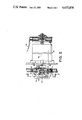
FIG. 2 is a cross-sectional view of the file reel, mounting hub, and actuator, taken along the line 2--2 of FIG. 1;
FIG. 3 is an end view of the file reel hub on the line 3--3 of FIG. 2; and
FIG. 4 is a perspective view of a portion of the locking mechanism.
DESCRIPTION OF THE PREFERRED EMBODIMENT
FIG. 1 shows a schematic view of a magnetic tape drive in which a file reel 10 is detachably mounted on the hub 11 of the present invention. A machine reel 12 is permanently mounted on the drive. Magnetic tape 13 is driven between file reel 10 and machine reel 12 past a read/write head 14.
FIGS. 2-4 show the locking hub of the present invention. File reel 10 has an annular opening with a circular peripheral surface 15 in the center. The locking hub includes a circular hub frame 16 rotatably mounted by the shaft 17 of the reel motor 18. The circular hub frame 16 fits within the annular opening of the file reel.
The locking actuator includes an end piece 19 and three guiding bolts 20-22 slidably mounting the end piece 19 in the hub frame 16. The guiding bolts extend through fingers 23-25 of end piece 19. Inclined camming surfaces 26-28, at the end of a respective finger 23-25, extend radially as the end piece 19 is moved axially.
Three arcuate locking members 29-31 are enclosed within the frame 16. Each locking member 29-31 has a respective circumferential surface 32-34 which matches the circular peripheral surface in the center of the file reel.
Circumferential surfaces 32-34 are of a friction material such as silicon rubber. Each of the circumferential surfaces 32-34 engage the circular peripheral surface of the file reel through almost 120°. Therefore, the locking members engage the peripheral surface of the file reel through almost 360°, the only exception being the three spaces between the locking members.
A rounded cam surface 35-37 is at the center of a respective locking member 29-31. Rounded cam surfaces 35-37 mate with the inclined camming surfaces 26-28 respectively on the actuator. When the actuator moves axially, the mating cam surfaces move the locking members radially outward.
This motion is guided. Two guides such as 38 and 39 are provided for each locking member. The guides extend through frame 16 and through slots such as 40 and 41, in each locking member. This arrangement guides the locking members in a radial movement.
When the end piece 19 is moved axially, camming surfaces 26-28 extend radially outward. This moves the arcuate locking members radially outward so that the entire circumferential surface of the locking member engages the peripheral surface 15 of the reel. This provides a good locking engagement between the hub and the reel.
Spring clips 42-44 extend between frame 16 and the corresponding locking member to bias the locking member inwardly and retain the locking member in the frame. Each locking member is moved radially outward against the bias by the camming surfaces of the actuator.
The actuator is moved axially by a pneumatically driven rod 45 (for automatic hubs), or manually operated latch 47 (for manual hubs). The rod 45 is moved axially outward by the pneumatic drive means of the aforementioned Smith patent which is supplied with pressurized air through inlet 46. Alternatively the hub is locked in place by operating the locking lever 47. Locking lever 47 has a camming surface 48 which engages a portion of the frame 16 to move the end piece 19 axially. This manually locks the hub to the reel. Locking lever 47 is pivoted at 49 to rotatably mount it in the end piece 19.
While a particular embodiment of the invention has been shown and described, various modifications are within the true spirit and scope of the invention. The appended claims are, therefore, intended to cover all such modifications.