US463536A - Centrifugal core-making machine - Google Patents
Centrifugal core-making machine Download PDFInfo
- Publication number
- US463536A US463536A US463536DA US463536A US 463536 A US463536 A US 463536A US 463536D A US463536D A US 463536DA US 463536 A US463536 A US 463536A
- Authority
- US
- United States
- Prior art keywords
- core
- making machine
- deflector
- shaft
- sand
- Prior art date
- Legal status (The legal status is an assumption and is not a legal conclusion. Google has not performed a legal analysis and makes no representation as to the accuracy of the status listed.)
- Expired - Lifetime
Links
- 244000035744 Hura crepitans Species 0.000 description 9
- 238000007790 scraping Methods 0.000 description 3
- 238000007493 shaping process Methods 0.000 description 3
- 239000004576 sand Substances 0.000 description 2
- 238000010276 construction Methods 0.000 description 1
- 239000003110 molding sand Substances 0.000 description 1
Images

Classifications
-
- B—PERFORMING OPERATIONS; TRANSPORTING
- B22—CASTING; POWDER METALLURGY
- B22C—FOUNDRY MOULDING
- B22C9/00—Moulds or cores; Moulding processes
- B22C9/10—Cores; Manufacture or installation of cores
Definitions
- Fig. 3 is an end view.
- Fig.4 is a cross-section.
- Fig. 5 is a rear end View.
- Fig. 6 is a detail view of the V-shaped j ournal-box.
- Fig. 7 is a perspective view of one of the scrapersupporting standards and the means for adjusting the scraper.
- Fig. 8 is an inside elevation of pulley M.
- the object of my invention is to provide a centrifugal core-making machine by the use of which an operative can make the greatest number of perfect cores in the shortestpossible time and with the least expense of physical and mechanical force.
- Another object of my invention is to provide a core-making machine which will produce cores that will notcrumble in handling.
- A designates the front standard, which is connected with the rear standard B by horizontal bars 0 O, re-enforced by diagonal braces D D, all of which are secured together by bolts or rivets a a.
- Two plates E extend horizontally across the machine, and are supported by the standards A B, to which they are secured by bolts 1) l). Extending longitudinally and horizontally from the top of one plate E to the top of the other plate are two bars F F, which support the shafts G and H.
- the shaft H has pulleys I and J and J while the shaft G has a pulley K, which has a belt L extending from it to the pulley M on the core-shaft N, thus rotating the core-shaft.
- a second pulley O on this shaft G is connected with a pulley on the shaft H by a belt P.
- a belt Q connects the pulley R 011 the shaft of the centrifugal sand-deflector S with the pulley I and another belt T connects the main drivepulley with the pulley J on the shaft H.
- Power is applied to the driving-pulley through a driving-belt leading from the source of power.
- Two adjustable eyebolts U Uat each end of the machine support two links V V,
- the standards are provided with eyebolts I or. guides o 0, through which slide the guides d d on the sandbox WV.
- the sand-box is reciprocated horizontally bya pitman e, connected to a wrist-pin f on the crank 9.
- the deflector is located, and in front of it is journaled the core-barrel shaft N whose journal-bearings i 2' are V- shaped and adjustable vertically to accommodate cores of different sizes and to compensate for wear.
- a knife or scraper j is located in front of the core-barrel shaft, and as the core-barrel is rotated the scraper shoves and scrapes the sand off and makes the core of uniform size throughout.
- the scraper is adjustable by means of the guides 7a and screw-bolts m m on standards Z Z, secured to the box below the machine.
- a ratchetwheel 0 may be keyed on the shaft and a pawl q, pivoted on the band-pulleyM.
- a core-making machine In a core-making machine, the combination of a rotary core-barrel, a deflector located at one side thereof, a scraper for scraping and shaping the core, a sand'box located above the deflector and having within it a horizontal screen and having downwardlyconverging side walls below the screen to form a contracted outlet, the said sand-box being capable of being longitudinally reciprocated, and means for reciprocating the same, substantially as shown'and described.
- a rotary corebarrel located at one side thereof, a rotary deflector located at one side thereof, a sand-box having downwardly-convergingsides and a screen above the outlet, the said box being suspended above the deflector by vertically-adjustable links and capable of being longitudinally reciprocated, and means for reciprocating the same, substantially as shown and described.
Landscapes
- Engineering & Computer Science (AREA)
- Mechanical Engineering (AREA)
- Soil Working Implements (AREA)
Description
J. E. MCGANNA.
GAL C GENT HINE.
No 463,536. Patented Nov. 17., 1891.
aw gnnn (No Model.) 4 sssssssss eet 2.
J. E. MOOANNA.-
G'ENTRIPUGAL 001m MAKINGMAOHINE. No. 463,536. Patented Nov. 17, 1891.
llili (No Model.)
J. E. MGOANNA. GBNTRII'UGAL GORE MAKING MACHINE.
4 Sheets-Sheet 3.
Patented Nov. 17,1891,
4 Sheets-Sheet 4.
(No Model.-)
J E McGANNA CENTRIFUGAL GORE MAKING MACHINE.
No. 463,536. Patented Nov. 17, 1891.
JOHN E.
FFICE.
ATENT MOCANNA, OF BALTIMORE, MARYLAND.
SPECIFICATION forming part of Letters Patent No. 463,536, dated November 17, 1891.
Application filed January 17. 1891.- Serial No. 378,084. (No model.)
To all whom it may concern:
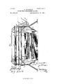
Be it known that I, JOHN E. MCOANNA, a citizen of the United States, residing at Baltimore, in the State of Maryland, have invented certain new and useful Improvements in Centrifugal Gore-Making Machines, of which the following is so full, clear, and exact a description as will enable others skilled in the art to which my invention appertains to make and use the same, reference being had to the accompanying drawings, in which Figure 1 is a side elevation of my improved device. Fig. 2 is a top plan view of the same.
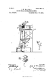
Fig. 3 is an end view. Fig.4 is a cross-section. Fig. 5 is a rear end View. Fig. 6 is a detail view of the V-shaped j ournal-box. Fig. 7 is a perspective view of one of the scrapersupporting standards and the means for adjusting the scraper. Fig. 8 is an inside elevation of pulley M.
The object of my invention is to provide a centrifugal core-making machine by the use of which an operative can make the greatest number of perfect cores in the shortestpossible time and with the least expense of physical and mechanical force.
Another object of my invention is to provide a core-making machine which will produce cores that will notcrumble in handling.
In the accompanying drawings, A designates the front standard, which is connected with the rear standard B by horizontal bars 0 O, re-enforced by diagonal braces D D, all of which are secured together by bolts or rivets a a. Two plates E extend horizontally across the machine, and are supported by the standards A B, to which they are secured by bolts 1) l). Extending longitudinally and horizontally from the top of one plate E to the top of the other plate are two bars F F, which support the shafts G and H. The shaft H has pulleys I and J and J while the shaft G has a pulley K, which has a belt L extending from it to the pulley M on the core-shaft N, thus rotating the core-shaft. A second pulley O on this shaft G is connected with a pulley on the shaft H by a belt P. A belt Q connects the pulley R 011 the shaft of the centrifugal sand-deflector S with the pulley I and another belt T connects the main drivepulley with the pulley J on the shaft H.
Power is applied to the driving-pulley through a driving-belt leading from the source of power. Two adjustable eyebolts U Uat each end of the machine support two links V V,
which in turn support the sand-box WV, hav
ing a screen X above the deflector.
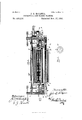
The standards are provided with eyebolts I or. guides o 0, through which slide the guides d d on the sandbox WV. The sand-box is reciprocated horizontally bya pitman e, connected to a wrist-pin f on the crank 9. Directly beneath the mouth of the hoppershaped sand-box W the deflector is located, and in front of it is journaled the core-barrel shaft N whose journal-bearings i 2' are V- shaped and adjustable vertically to accommodate cores of different sizes and to compensate for wear.
A knife or scraper j is located in front of the core-barrel shaft, and as the core-barrel is rotated the scraper shoves and scrapes the sand off and makes the core of uniform size throughout. The scraper is adjustable by means of the guides 7a and screw-bolts m m on standards Z Z, secured to the box below the machine.
As a means for allowing the core-barrel to be turned by hand when desired, a ratchetwheel 0 may be keyed on the shaft and a pawl q, pivoted on the band-pulleyM. hen
power is applied through the belt L, the pulley M, through the pawl and ratchet, will rotate the. shaft N; but when the belt L is not running the shaft N may be turned independently of the pulley by a crank q applied to the end thereof.
The operation of my device is as follows: Motion is imparted to the machinery through the drive-belt 47, and molding-sand is putinto the sand-boxrfrom which it is sifted and falls onto the deflector and is thrown thence by the blades S with great force against the corebarrel, on the roughened surface of which it packs hard and is planed smooth by the scraper and the core is finished.
I do not limit myself to the exact details of mechanical construction used in the device shown and described, as many of the elements may be altered and niechaninal equivalents substituted therefor without departing from the spirit of my invention.
hat I believe to be new, and desire to secure by Letters Patent, and what I therefore claim, is
1. In a core-making machine, a core-barrel support and a deflector with radial curved blades journaled at one side thereof, in combination with a sand-box located above the deflector and capable of being longitudinally reciprocated and means for reciprocating the same, substantially as shown and described.
2. In a core-making machine, the combination of a rotary core-barrel, a deflector with radial curved blades journaled at one side thereof, a scraper for scraping and shaping the core, a sandbox supported above the deflector and capable of being longitudinally reciprocated, and means for reciprocating the same, substantially as shown and described.
3. In a core-making machine, the combinatlon of a rotary core barrel, a'deflector located at one side of the same, a scraper for scraping and shaping the core, a sand-box suspended above the deflector by verticallyadjustable links and capable of being recipl'ocated longitudinally, and means for reciprocating the sa me, substantially as shown and described.
4:. In a core-making machine, the combination of a rotary core-barrel, a deflector located at one side thereof, a scraper for scraping and shaping the core, a sand'box located above the deflector and having within it a horizontal screen and having downwardlyconverging side walls below the screen to form a contracted outlet, the said sand-box being capable of being longitudinally reciprocated, and means for reciprocating the same, substantially as shown'and described.
5. In a core-making machine, a rotary corebarrel, a rotary deflector located at one side thereof, a sand-box having downwardly-convergingsides and a screen above the outlet, the said box being suspended above the deflector by vertically-adjustable links and capable of being longitudinally reciprocated, and means for reciprocating the same, substantially as shown and described.
In testimony whereof I affix my signature in the presence of two witnesses.
JOHN E. Mac-ANNA.
\Vitnesses:
CHAS. E. BARBER, hIAR'lIN .I.MOSI1ANE.
Publications (1)
| Publication Number | Publication Date |
|---|---|
| US463536A true US463536A (en) | 1891-11-17 |
Family
ID=2532408
Family Applications (1)
| Application Number | Title | Priority Date | Filing Date |
|---|---|---|---|
| US463536D Expired - Lifetime US463536A (en) | Centrifugal core-making machine |
Country Status (1)
| Country | Link |
|---|---|
| US (1) | US463536A (en) |
-
0
- US US463536D patent/US463536A/en not_active Expired - Lifetime
Similar Documents
| Publication | Publication Date | Title |
|---|---|---|
| US463536A (en) | Centrifugal core-making machine | |
| US493603A (en) | sibley | |
| US100302A (en) | Improvement in feat-machines | |
| US783186A (en) | Automatic proportioning-machine. | |
| US1730300A (en) | Grinding mill | |
| US669735A (en) | Hulling-machine. | |
| US348890A (en) | Grain-cleaning machine | |
| US229810A (en) | Clay-tempering machine | |
| US426796A (en) | Hungary | |
| US312983A (en) | doyle | |
| US448538A (en) | Flour-bolting apparatus | |
| US187040A (en) | Improvement in middlings-separators | |
| US329708A (en) | Clay-pulverizer | |
| US644774A (en) | Oat-clipping machine. | |
| US175148A (en) | Improvement in hulling-machines | |
| US655740A (en) | Brick-mold-sanding machine. | |
| US255419A (en) | Machine for bolting and purifying flour and middlings | |
| US491623A (en) | Teenths to william ii | |
| US331553A (en) | Gael schlickeysen and eduaed beeslaueb | |
| US665802A (en) | Means for forming molds. | |
| US613707A (en) | mckeown | |
| US1082960A (en) | Slow-speed chilian mill. | |
| US359659A (en) | Crushing and grinding mill | |
| US3263967A (en) | Continuous muller | |
| US1309834A (en) | Method of making molds for steel castings |