US4635156A - Cleaning cassette for magnetic tape apparatus - Google Patents
Cleaning cassette for magnetic tape apparatus Download PDFInfo
- Publication number
- US4635156A US4635156A US06/526,122 US52612283A US4635156A US 4635156 A US4635156 A US 4635156A US 52612283 A US52612283 A US 52612283A US 4635156 A US4635156 A US 4635156A
- Authority
- US
- United States
- Prior art keywords
- tape
- cleaning
- cassette
- liquid
- reel hubs
- Prior art date
- Legal status (The legal status is an assumption and is not a legal conclusion. Google has not performed a legal analysis and makes no representation as to the accuracy of the status listed.)
- Expired - Lifetime
Links
- 238000004140 cleaning Methods 0.000 title claims abstract description 81
- 239000007788 liquid Substances 0.000 claims abstract description 38
- 239000000463 material Substances 0.000 claims abstract description 9
- 230000002745 absorbent Effects 0.000 claims abstract description 8
- 239000002250 absorbent Substances 0.000 claims abstract description 8
- UQSXHKLRYXJYBZ-UHFFFAOYSA-N Iron oxide Chemical compound [Fe]=O UQSXHKLRYXJYBZ-UHFFFAOYSA-N 0.000 description 2
- 229920006395 saturated elastomer Polymers 0.000 description 2
- 239000004698 Polyethylene Substances 0.000 description 1
- 230000002159 abnormal effect Effects 0.000 description 1
- 238000009825 accumulation Methods 0.000 description 1
- 239000000853 adhesive Substances 0.000 description 1
- 230000001070 adhesive effect Effects 0.000 description 1
- 238000001514 detection method Methods 0.000 description 1
- 229920001971 elastomer Polymers 0.000 description 1
- 230000000977 initiatory effect Effects 0.000 description 1
- 238000012544 monitoring process Methods 0.000 description 1
- 239000002245 particle Substances 0.000 description 1
- 230000002093 peripheral effect Effects 0.000 description 1
- -1 polyethylene Polymers 0.000 description 1
- 229920000573 polyethylene Polymers 0.000 description 1
- 230000002441 reversible effect Effects 0.000 description 1
Images

Classifications
-
- G—PHYSICS
- G11—INFORMATION STORAGE
- G11B—INFORMATION STORAGE BASED ON RELATIVE MOVEMENT BETWEEN RECORD CARRIER AND TRANSDUCER
- G11B23/00—Record carriers not specific to the method of recording or reproducing; Accessories, e.g. containers, specially adapted for co-operation with the recording or reproducing apparatus ; Intermediate mediums; Apparatus or processes specially adapted for their manufacture
- G11B23/02—Containers; Storing means both adapted to cooperate with the recording or reproducing means
- G11B23/04—Magazines; Cassettes for webs or filaments
- G11B23/049—Cassettes for special applications not otherwise provided for
-
- G—PHYSICS
- G11—INFORMATION STORAGE
- G11B—INFORMATION STORAGE BASED ON RELATIVE MOVEMENT BETWEEN RECORD CARRIER AND TRANSDUCER
- G11B5/00—Recording by magnetisation or demagnetisation of a record carrier; Reproducing by magnetic means; Record carriers therefor
- G11B5/41—Cleaning of heads
-
- Y—GENERAL TAGGING OF NEW TECHNOLOGICAL DEVELOPMENTS; GENERAL TAGGING OF CROSS-SECTIONAL TECHNOLOGIES SPANNING OVER SEVERAL SECTIONS OF THE IPC; TECHNICAL SUBJECTS COVERED BY FORMER USPC CROSS-REFERENCE ART COLLECTIONS [XRACs] AND DIGESTS
- Y10—TECHNICAL SUBJECTS COVERED BY FORMER USPC
- Y10S—TECHNICAL SUBJECTS COVERED BY FORMER USPC CROSS-REFERENCE ART COLLECTIONS [XRACs] AND DIGESTS
- Y10S15/00—Brushing, scrubbing, and general cleaning
- Y10S15/12—Tape head cleaner
-
- Y—GENERAL TAGGING OF NEW TECHNOLOGICAL DEVELOPMENTS; GENERAL TAGGING OF CROSS-SECTIONAL TECHNOLOGIES SPANNING OVER SEVERAL SECTIONS OF THE IPC; TECHNICAL SUBJECTS COVERED BY FORMER USPC CROSS-REFERENCE ART COLLECTIONS [XRACs] AND DIGESTS
- Y10—TECHNICAL SUBJECTS COVERED BY FORMER USPC
- Y10S—TECHNICAL SUBJECTS COVERED BY FORMER USPC CROSS-REFERENCE ART COLLECTIONS [XRACs] AND DIGESTS
- Y10S15/00—Brushing, scrubbing, and general cleaning
- Y10S15/13—Magnetic tape cleaner
Definitions
- the present invention relates to cleaning devices for cleaning the components of magnetic tape recording and/or play-back apparatus.
- cleaning cassettes incorporates a fixed tank of cleaning liquid which is applied to a tape then used to apply the cleaning liquid on the tape to the components to be cleaned.
- the use of such cassettes requires attention from the user, and the cleaning liquid while applied continuously to the tape, may not be uniformly distributed thereon which reduces cleaning effectiveness.
- the tape is unwound from the reel hubs of the cassette at high speed whereas it is normally unwound only at a very low speed (a few centimeters per second) which presents a high risk of damage to the tape or components of the apparatus;
- the main object of the present invention is to solve the problems mentioned above by providing a cleaning cassette which applies cleaning liquid to the components of the apparatus without sticking to such components as the drum of a VCR or capstans.
- FIG. 1 is a plan view of a cassette constructed in accordance with the invention
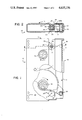
- FIG. 2 is a sectional view taken in the planes of lines 2--2 in FIG. 1;
- FIG. 3 is an enlarged view of the cleaning reel
- FIG. 4 is a sectional view taken in the plane of lines 4--4 in FIG. 3;
- FIG. 5 is a diagrammatic view of the cassette and controller of the apparatus, and elements for detecting the cassette as it is inserted into the apparatus.
- a cleaning cassette 10 having a cleaning tape 11 connected to a pair of reel hubs 12, 13 rotatably mounted in the cassette housing 14.
- the cleaning tape is preferably made of uncoated polyethylene film, and is trained around rods or rollers 18 so as to extend across the front edge of the cassette housing 14, where it is protected by a removable cover 19.
- the cassette includes a source of cleaning liquid herein shown as a roller 20 rotatable on a shaft 21 and having a core 22 of absorbment material such as felt or sponge rubber.
- a source of cleaning liquid herein shown as a roller 20 rotatable on a shaft 21 and having a core 22 of absorbment material such as felt or sponge rubber.
- the core 22 of absorbent material may be saturated with cleaning liquid.
- a segment 23 of the core 22 is exposed on and protrudes from, the periphery of the roller 20, except for this segment 23 the core 22 being enclosed in an impervious shell 20a.
- the cassette housing has an opening 30 formed by a disc shaped element 32 fixed to the outer wall 34 of the housing 14.
- the device 36 is used providing a ring of spaced holes 36a through which liquid passes to the core 22.
- the roller 20 As the tape is driven from reel hub to reel hub, the roller 20 is driven and during each rotation of the roller, applies liquid from the core to the outer surface of the tape over a sector corresponding to the surface of the protruding segment 23 of the core.
- the surface of the tape 11 is wet intermittently in order to avoid sticking of the tape to the drum carrying magnetic heads, or to tape driving means, of the tape apparatus being cleaned with the cleaning cassette.
- the tape is wetted every six centimeters for a length of approximately eight millimeters, but this may be varied as desired by providing a wider or narrower segment 24 through which the core 22 protrudes.
- a duplicate roller 20 1 similar to the first roller 20 is provided on the other end of the cassette to engage the tape 11 near the other reel hub 13.
- the duplicate roller 20 1 serves to apply liquid to the surface of the tape 11 intermittently, for cleaning components of magnetic tape apparatus.
- a cleaning cassette 10 (FIG. 1) is provided with a recess 40 in the housing 14 which serves as a code element representing the cleaning function of the cassette 10, and distinguishing this type of cassette from standard cassettes in which the recess 40 is capped or covered.
- Means are also provided, herein shown as a switch actuator 46, in the magnetic tape apparatus adapted to receive this cassette 10, for detecting the code element on a cassette 10 received in the apparatus.
- the switch actuator 46 is adapted to penetrate the recess 40, closing the contacts 48 of a switch 50 included in the apparatus and connected to a controller 52 operable to direct the magnetic tape apparatus through a cleaning cycle responsive to detecting a code element on a cassette received in the apparatus.
- the cleaning cycle initiated automatically when the cassette 10 is inserted also involves:
- the cleaning tape should be driven at normal playing speed in the apparatus during the cleaning cycle. Since the automatic stop control of the magnetic tape apparatus may not operate perfectly with a clean-cassette, it is also desired to stop the tape automatically before the end of the tape is reached. This may be accomplished by timing the transfer of the tape, or by monitoring tape movement. Therefore, it is also desired to include the step:
- a microprocessor based control system 52 is preferably provided, having a program stored in memory 54 and controlling the apparatus 56 to carry out these functions, as indicated in the chart of functions included in FIG. 5.
Landscapes
- Cleaning In General (AREA)
Abstract
Description
Claims (7)
Applications Claiming Priority (4)
| Application Number | Priority Date | Filing Date | Title |
|---|---|---|---|
| BE209004 | 1982-09-13 | ||
| BE0/209004A BE894385A (en) | 1982-09-13 | 1982-09-13 | CLEANING CASSETTE OR CARTRIDGE FOR RECORDING AND / OR READING DEVICES OF MAGNETIC TAPES |
| BE209006 | 1982-09-13 | ||
| BE0/209006A BE894387A (en) | 1982-09-13 | 1982-09-13 | METHOD FOR CLEANING THE ORGANS OF A RECORDING AND READING DEVICE OF MAGNETIC TAPES-CASSETTE AND APPARATUS FOR IMPLEMENTING SAID METHOD |
Publications (1)
| Publication Number | Publication Date |
|---|---|
| US4635156A true US4635156A (en) | 1987-01-06 |
Family
ID=25653301
Family Applications (1)
| Application Number | Title | Priority Date | Filing Date |
|---|---|---|---|
| US06/526,122 Expired - Lifetime US4635156A (en) | 1982-09-13 | 1983-08-24 | Cleaning cassette for magnetic tape apparatus |
Country Status (1)
| Country | Link |
|---|---|
| US (1) | US4635156A (en) |
Cited By (4)
| Publication number | Priority date | Publication date | Assignee | Title |
|---|---|---|---|---|
| US4722016A (en) * | 1983-09-19 | 1988-01-26 | Olympus Optical Co., Ltd. | Tape cassette for cleaning use |
| BE1001875A5 (en) * | 1988-12-05 | 1990-04-03 | Staar Sa | Improvements to sound recording and / or reading magnetic tapes. |
| EP0430262A3 (en) * | 1989-12-01 | 1992-05-20 | Nikon Corporation | Camera having a magnetic head, film means load to the same and a camera system |
| EP0506856A4 (en) * | 1989-12-28 | 1993-05-26 | Tandy Corporation | Method and apparatus for cleaning portions of a video cassette recorder |
Citations (7)
| Publication number | Priority date | Publication date | Assignee | Title |
|---|---|---|---|---|
| DE2158994A1 (en) * | 1971-05-18 | 1972-12-07 | Metrosound Mfg Co Ltd | Cleaning device for tape recorders |
| US3955214A (en) * | 1974-08-26 | 1976-05-04 | Tobins Industries Corporation | Device for cleaning the magnetic head and capstan roller of a cassette-type recording and/or playback unit in response to operation of the tape drive of the unit |
| US4324014A (en) * | 1978-11-20 | 1982-04-13 | Innovative Computer Products | Cassette cleaner |
| US4377831A (en) * | 1979-03-15 | 1983-03-22 | Innovative Computer Products Corp. | Non-abrasive magnetic head cleaning system |
| US4388663A (en) * | 1979-11-10 | 1983-06-14 | Konig-Electronic Friedrich W. Konig | Cleaning cassette for a tape machine |
| US4470089A (en) * | 1981-12-21 | 1984-09-04 | International Jensen Incorporated | Tape unit cleaning device |
| US4498113A (en) * | 1981-04-14 | 1985-02-05 | Allsop, Inc. | Apparatus and method for cleaning a video player/recorder |
-
1983
- 1983-08-24 US US06/526,122 patent/US4635156A/en not_active Expired - Lifetime
Patent Citations (8)
| Publication number | Priority date | Publication date | Assignee | Title |
|---|---|---|---|---|
| DE2158994A1 (en) * | 1971-05-18 | 1972-12-07 | Metrosound Mfg Co Ltd | Cleaning device for tape recorders |
| US3783470A (en) * | 1971-05-18 | 1974-01-08 | Metrosound Mfg Co Ltd | Cleaner for tape cartridge players |
| US3955214A (en) * | 1974-08-26 | 1976-05-04 | Tobins Industries Corporation | Device for cleaning the magnetic head and capstan roller of a cassette-type recording and/or playback unit in response to operation of the tape drive of the unit |
| US4324014A (en) * | 1978-11-20 | 1982-04-13 | Innovative Computer Products | Cassette cleaner |
| US4377831A (en) * | 1979-03-15 | 1983-03-22 | Innovative Computer Products Corp. | Non-abrasive magnetic head cleaning system |
| US4388663A (en) * | 1979-11-10 | 1983-06-14 | Konig-Electronic Friedrich W. Konig | Cleaning cassette for a tape machine |
| US4498113A (en) * | 1981-04-14 | 1985-02-05 | Allsop, Inc. | Apparatus and method for cleaning a video player/recorder |
| US4470089A (en) * | 1981-12-21 | 1984-09-04 | International Jensen Incorporated | Tape unit cleaning device |
Cited By (6)
| Publication number | Priority date | Publication date | Assignee | Title |
|---|---|---|---|---|
| US4722016A (en) * | 1983-09-19 | 1988-01-26 | Olympus Optical Co., Ltd. | Tape cassette for cleaning use |
| BE1001875A5 (en) * | 1988-12-05 | 1990-04-03 | Staar Sa | Improvements to sound recording and / or reading magnetic tapes. |
| EP0373138A1 (en) * | 1988-12-05 | 1990-06-13 | Staar Societe Anonyme | A drying device for recorder/player units |
| US5109313A (en) * | 1988-12-05 | 1992-04-28 | Staar S.A. | Drying cassette for recorder/player units |
| EP0430262A3 (en) * | 1989-12-01 | 1992-05-20 | Nikon Corporation | Camera having a magnetic head, film means load to the same and a camera system |
| EP0506856A4 (en) * | 1989-12-28 | 1993-05-26 | Tandy Corporation | Method and apparatus for cleaning portions of a video cassette recorder |
Similar Documents
| Publication | Publication Date | Title |
|---|---|---|
| EP0617427B1 (en) | Tape cassette for cleaning vcr heads and transport components | |
| GB2127203A (en) | Cleaning cassette for magnetic tape apparatus | |
| US4635156A (en) | Cleaning cassette for magnetic tape apparatus | |
| GB2127204A (en) | Cleaning magnetic tape apparatus | |
| CA1203896A (en) | Cancellation device for cancelling a temporary stop mode in a recording and/or reproducing apparatus | |
| US4811149A (en) | Method and apparatus for cleaning operating components of a video player/recorder | |
| JP2822581B2 (en) | Tape recording and playback device | |
| US4071863A (en) | Stationary magnetic tape transducing system with means for controlling the air bearing support | |
| JPH0353694B2 (en) | ||
| JPH03241512A (en) | Cleaning device for rotarymagnetic head | |
| JPH03178019A (en) | Rotary head type magnetic recording and reproducing device | |
| JPH0363143B2 (en) | ||
| JPS5914932Y2 (en) | Tape travel control device | |
| JPH0413774Y2 (en) | ||
| JPS6019052B2 (en) | magnetic recording and reproducing device | |
| JPS59113520A (en) | magnetic recording and reproducing device | |
| JPH08273128A (en) | Rotating head type magnetic recording / reproducing device | |
| JPS6152342U (en) | ||
| JPS5857619A (en) | Magnetic recorder and reproducer | |
| JPS60117438A (en) | Magnetic picture recording device | |
| JPH02108214A (en) | Rotating drum cleaning device for magnetic recording and reproducing equipment | |
| WO1987005143A1 (en) | Method and apparatus for cleaning operating components of a video player/recorder | |
| JPS6244336B2 (en) | ||
| JPS63144448A (en) | Recording or reproducing device | |
| JPH08227510A (en) | Rotating head type magnetic recording / reproducing device |
Legal Events
| Date | Code | Title | Description |
|---|---|---|---|
| AS | Assignment |
Owner name: STAAR, S.A., 19-21 RUE DES ATELIERS, B-1080 BRUSSE Free format text: ASSIGNMENT OF ASSIGNORS INTEREST.;ASSIGNOR:DE COSTEMORE D'ARC, STEPHANE D'ALAYER;REEL/FRAME:004174/0850 Effective date: 19830809 Owner name: STAAR, S.A., BELGIUM Free format text: ASSIGNMENT OF ASSIGNORS INTEREST;ASSIGNOR:DE COSTEMORE D'ARC, STEPHANE D'ALAYER;REEL/FRAME:004174/0850 Effective date: 19830809 |
|
| STCF | Information on status: patent grant |
Free format text: PATENTED CASE |
|
| CC | Certificate of correction | ||
| FEPP | Fee payment procedure |
Free format text: PAYOR NUMBER ASSIGNED (ORIGINAL EVENT CODE: ASPN); ENTITY STATUS OF PATENT OWNER: SMALL ENTITY Free format text: PAT HLDR NO LONGER CLAIMS SMALL ENT STAT AS SMALL BUSINESS (ORIGINAL EVENT CODE: LSM2); ENTITY STATUS OF PATENT OWNER: SMALL ENTITY |
|
| AS | Assignment |
Owner name: VIVA MAGNETICS LIMITED, 16TH FLOOR, E ON FTY. BLDG Free format text: ASSIGNMENT OF ASSIGNORS INTEREST.;ASSIGNOR:STAAR S.A., A CO. OF BELGIUM;REEL/FRAME:005262/0395 Effective date: 19891215 Owner name: VIVA MAGNETICS LIMITED, A CORP. OF HONG KONG,HONG Free format text: ASSIGNMENT OF ASSIGNORS INTEREST;ASSIGNOR:STAAR S.A., A CO. OF BELGIUM;REEL/FRAME:005262/0395 Effective date: 19891215 |
|
| FPAY | Fee payment |
Year of fee payment: 4 |
|
| FEPP | Fee payment procedure |
Free format text: PAT HOLDER CLAIMS SMALL ENTITY STATUS - SMALL BUSINESS (ORIGINAL EVENT CODE: SM02); ENTITY STATUS OF PATENT OWNER: SMALL ENTITY |
|
| FPAY | Fee payment |
Year of fee payment: 8 |
|
| FEPP | Fee payment procedure |
Free format text: PAYER NUMBER DE-ASSIGNED (ORIGINAL EVENT CODE: RMPN); ENTITY STATUS OF PATENT OWNER: SMALL ENTITY |
|
| FPAY | Fee payment |
Year of fee payment: 12 |
|
| FEPP | Fee payment procedure |
Free format text: PAYOR NUMBER ASSIGNED (ORIGINAL EVENT CODE: ASPN); ENTITY STATUS OF PATENT OWNER: SMALL ENTITY |