US4634159A - Harness supporting structure at inner part of door - Google Patents
Harness supporting structure at inner part of door Download PDFInfo
- Publication number
- US4634159A US4634159A US06/833,025 US83302586A US4634159A US 4634159 A US4634159 A US 4634159A US 83302586 A US83302586 A US 83302586A US 4634159 A US4634159 A US 4634159A
- Authority
- US
- United States
- Prior art keywords
- wire harness
- door
- guide
- supporting structure
- reinforced bracket
- Prior art date
- Legal status (The legal status is an assumption and is not a legal conclusion. Google has not performed a legal analysis and makes no representation as to the accuracy of the status listed.)
- Expired - Fee Related
Links
- 238000005452 bending Methods 0.000 claims 1
- 239000011521 glass Substances 0.000 description 2
- 238000009434 installation Methods 0.000 description 2
- 239000000463 material Substances 0.000 description 2
- 238000000034 method Methods 0.000 description 1
- 238000012986 modification Methods 0.000 description 1
- 230000004048 modification Effects 0.000 description 1
Images

Classifications
-
- B—PERFORMING OPERATIONS; TRANSPORTING
- B60—VEHICLES IN GENERAL
- B60J—WINDOWS, WINDSCREENS, NON-FIXED ROOFS, DOORS, OR SIMILAR DEVICES FOR VEHICLES; REMOVABLE EXTERNAL PROTECTIVE COVERINGS SPECIALLY ADAPTED FOR VEHICLES
- B60J5/00—Doors
- B60J5/04—Doors arranged at the vehicle sides
- B60J5/042—Reinforcement elements
- B60J5/0422—Elongated type elements, e.g. beams, cables, belts or wires
- B60J5/0423—Elongated type elements, e.g. beams, cables, belts or wires characterised by position in the lower door structure
- B60J5/0433—Elongated type elements, e.g. beams, cables, belts or wires characterised by position in the lower door structure the elements being arranged at the lock area
-
- B—PERFORMING OPERATIONS; TRANSPORTING
- B60—VEHICLES IN GENERAL
- B60R—VEHICLES, VEHICLE FITTINGS, OR VEHICLE PARTS, NOT OTHERWISE PROVIDED FOR
- B60R16/00—Electric or fluid circuits specially adapted for vehicles and not otherwise provided for; Arrangement of elements of electric or fluid circuits specially adapted for vehicles and not otherwise provided for
- B60R16/02—Electric or fluid circuits specially adapted for vehicles and not otherwise provided for; Arrangement of elements of electric or fluid circuits specially adapted for vehicles and not otherwise provided for electric constitutive elements
- B60R16/0207—Wire harnesses
- B60R16/0215—Protecting, fastening and routing means therefor
-
- E—FIXED CONSTRUCTIONS
- E05—LOCKS; KEYS; WINDOW OR DOOR FITTINGS; SAFES
- E05B—LOCKS; ACCESSORIES THEREFOR; HANDCUFFS
- E05B79/00—Mounting or connecting vehicle locks or parts thereof
- E05B79/02—Mounting of vehicle locks or parts thereof
- E05B79/04—Mounting of lock casings to the vehicle, e.g. to the wing
-
- Y—GENERAL TAGGING OF NEW TECHNOLOGICAL DEVELOPMENTS; GENERAL TAGGING OF CROSS-SECTIONAL TECHNOLOGIES SPANNING OVER SEVERAL SECTIONS OF THE IPC; TECHNICAL SUBJECTS COVERED BY FORMER USPC CROSS-REFERENCE ART COLLECTIONS [XRACs] AND DIGESTS
- Y10—TECHNICAL SUBJECTS COVERED BY FORMER USPC
- Y10S—TECHNICAL SUBJECTS COVERED BY FORMER USPC CROSS-REFERENCE ART COLLECTIONS [XRACs] AND DIGESTS
- Y10S292/00—Closure fasteners
- Y10S292/23—Vehicle door latches
-
- Y—GENERAL TAGGING OF NEW TECHNOLOGICAL DEVELOPMENTS; GENERAL TAGGING OF CROSS-SECTIONAL TECHNOLOGIES SPANNING OVER SEVERAL SECTIONS OF THE IPC; TECHNICAL SUBJECTS COVERED BY FORMER USPC CROSS-REFERENCE ART COLLECTIONS [XRACs] AND DIGESTS
- Y10—TECHNICAL SUBJECTS COVERED BY FORMER USPC
- Y10T—TECHNICAL SUBJECTS COVERED BY FORMER US CLASSIFICATION
- Y10T292/00—Closure fasteners
- Y10T292/57—Operators with knobs or handles
-
- Y—GENERAL TAGGING OF NEW TECHNOLOGICAL DEVELOPMENTS; GENERAL TAGGING OF CROSS-SECTIONAL TECHNOLOGIES SPANNING OVER SEVERAL SECTIONS OF THE IPC; TECHNICAL SUBJECTS COVERED BY FORMER USPC CROSS-REFERENCE ART COLLECTIONS [XRACs] AND DIGESTS
- Y10—TECHNICAL SUBJECTS COVERED BY FORMER USPC
- Y10T—TECHNICAL SUBJECTS COVERED BY FORMER US CLASSIFICATION
- Y10T292/00—Closure fasteners
- Y10T292/62—Bolt casings
Definitions
- the present invention relates to the supporting structure of the wire harness for electrical parts located in the internal space formed between the inner panel and outer panel of the door.
- wire harness for the electrical parts such as keyhole illuminator or keyless entry system etc are arranged.
- the aforementioned wire harness 14 for electrical part 12 is supported by the guide 16.
- the object of the present invention is to provide a harness supporting structure in the internal part of the door with abridgement in the material of the guide to improve the efficiency of the internal space.
- the other object of the present invention is to provide a harness supporting structure in the internal part of the door which can improve ease in the laying down of the wire harness within the door.
- the other object of the present invention is to provide a harness supporting structure in the internal part of the door which can positively support the wire harness even if the internal space of the door is small.
- One of the feature of the present invention is that a reinforced bracket which has a guide and harness holders provided on the guide is fastened jointly with a doorlock in the internal space of the door.
- the wire harness which is extended from the electrical part is laid along the aforementioned guide and fixed and supported at the harness holders.
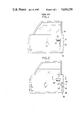
- FIG. 1 is an elevation of the door with the prior art wire harness supporting structure
- FIG. 2 is an elevation of a door with a wire harness supporting structure embodying the present invention
- FIG. 3 is an enlarged cross sectional view through line II--II of FIG. 2;
- FIG. 4 is the diagonal view of the door lock shown in FIG. 3;
- FIG. 5 is the diagonal view of the reinforced bracket shown in FIG. 3.
- the wire harness supporting structure according to the present invention is shown with the reference number 30.
- the door lock 42 is jointly fastened via the reinforced bracket 40, which has the function to support the wire harness 38, to a inner panel 34 of the door 36 formed by an outer panel 32 and the inner panel 34.
- the door lock 42 is provided with a lock unit 44 which has the function to maintain the above mentioned door in locked position.
- a lock mechanism or a lock operating mechanism (neither of which is shown in any of the schematics) is provided to restrict or release the movement of a latch 46 which can freely engage or disengage with the chasis side striker.
- the reinforced bracket 40 as shown in FIG. 5 has a shape almost identical to that of the lock unit 44 to easy the fastening of it together with the lock unit 44 when installed on the inner panel 34 of the door.
- the guide 48 rises vertically from the upper edge of the bracket 40, and facing this, a pair of the harness holders 50, 50' project upward integrally with the guide 48 for fixing the wire harness 38 on the guide 48. Both sides of the guide 48 are bent at short length on the outward side to form the flanges 54, 54' so that the wire harness 38 extending from the electrical part 52 can be guided in easily.
- harness holders 50, 50' are made into a tongue shape in order that the aforementioned guide 48 can be folded over horizontally.
- the installation procedure of the wire harness is explained in the next.
- the reinforced bracket 40 is jointly fastened with the door lock 42 on the inner panel 34.
- the harness holders 50, 50' are left in a standing -up position.
- the wire harness 38 extending from the electrical part 52 is laid along the guide 48. In this case, the wire harness 38 can be guided in smoothly without getting caught in by both the flanges 54, 54' bent on the outward side.
- harness holders 50, 50' are folded over to fix and support the wire harness 38 on the guide 48. This prevents the shaking of wireharness 38.
- the harness supporting structure at the internal part of the door can positively support the wire harness even if the space inside the door is small. Moreover, due to abbreviation of material for the guide, the workability improves with the reduction of cost at the same time.
Landscapes
- Engineering & Computer Science (AREA)
- Mechanical Engineering (AREA)
- Installation Of Indoor Wiring (AREA)
- Electric Cable Arrangement Between Relatively Moving Parts (AREA)
Abstract
Description
Claims (5)
Applications Claiming Priority (2)
| Application Number | Priority Date | Filing Date | Title |
|---|---|---|---|
| JP60-36443 | 1985-02-27 | ||
| JP60036443A JPS61196821A (en) | 1985-02-27 | 1985-02-27 | Harness supporting structure in door inside |
Publications (1)
| Publication Number | Publication Date |
|---|---|
| US4634159A true US4634159A (en) | 1987-01-06 |
Family
ID=12469951
Family Applications (1)
| Application Number | Title | Priority Date | Filing Date |
|---|---|---|---|
| US06/833,025 Expired - Fee Related US4634159A (en) | 1985-02-27 | 1986-02-26 | Harness supporting structure at inner part of door |
Country Status (2)
| Country | Link |
|---|---|
| US (1) | US4634159A (en) |
| JP (1) | JPS61196821A (en) |
Cited By (3)
| Publication number | Priority date | Publication date | Assignee | Title |
|---|---|---|---|---|
| US5466036A (en) * | 1994-05-09 | 1995-11-14 | Chrylser Corporation | Vehicle wire routing apparatus |
| US20180073281A1 (en) * | 2015-04-08 | 2018-03-15 | Kiekert Ag | Motor vehicle door lock |
| US20180291653A1 (en) * | 2017-04-05 | 2018-10-11 | Toyota Motor Engineering & Manufacturing North America, Inc. | Protection block for vehicle door lock |
Citations (4)
| Publication number | Priority date | Publication date | Assignee | Title |
|---|---|---|---|---|
| US3854763A (en) * | 1973-07-18 | 1974-12-17 | Von Duprin Inc | Electrical and mechanical dogging device |
| US4052094A (en) * | 1975-01-17 | 1977-10-04 | Gkn-Stenman Ab | Sandwich-type motor vehicle door and flush mounted lock cassette |
| US4054307A (en) * | 1976-11-08 | 1977-10-18 | General Motors Corporation | Mechanical control system for vehicle door lock |
| US4342209A (en) * | 1979-03-24 | 1982-08-03 | Kiekert Gmbh & Co. Kommanditgesellschaft | Central vehicle door-lock system |
-
1985
- 1985-02-27 JP JP60036443A patent/JPS61196821A/en active Pending
-
1986
- 1986-02-26 US US06/833,025 patent/US4634159A/en not_active Expired - Fee Related
Patent Citations (4)
| Publication number | Priority date | Publication date | Assignee | Title |
|---|---|---|---|---|
| US3854763A (en) * | 1973-07-18 | 1974-12-17 | Von Duprin Inc | Electrical and mechanical dogging device |
| US4052094A (en) * | 1975-01-17 | 1977-10-04 | Gkn-Stenman Ab | Sandwich-type motor vehicle door and flush mounted lock cassette |
| US4054307A (en) * | 1976-11-08 | 1977-10-18 | General Motors Corporation | Mechanical control system for vehicle door lock |
| US4342209A (en) * | 1979-03-24 | 1982-08-03 | Kiekert Gmbh & Co. Kommanditgesellschaft | Central vehicle door-lock system |
Cited By (5)
| Publication number | Priority date | Publication date | Assignee | Title |
|---|---|---|---|---|
| US5466036A (en) * | 1994-05-09 | 1995-11-14 | Chrylser Corporation | Vehicle wire routing apparatus |
| US20180073281A1 (en) * | 2015-04-08 | 2018-03-15 | Kiekert Ag | Motor vehicle door lock |
| US11131125B2 (en) * | 2015-04-08 | 2021-09-28 | Kiekert Ag | Motor vehicle door lock |
| US20180291653A1 (en) * | 2017-04-05 | 2018-10-11 | Toyota Motor Engineering & Manufacturing North America, Inc. | Protection block for vehicle door lock |
| US10676970B2 (en) * | 2017-04-05 | 2020-06-09 | Toyota Motor Engineering & Manufacturing North America, Inc. | Protection block for vehicle door lock |
Also Published As
| Publication number | Publication date |
|---|---|
| JPS61196821A (en) | 1986-09-01 |
Similar Documents
| Publication | Publication Date | Title |
|---|---|---|
| RU2243623C2 (en) | Holding clamp for installation and wiring duct | |
| US20010017472A1 (en) | Vehicle door and process of assembling the vehicle door | |
| US6254041B1 (en) | Cable conduit | |
| KR100623318B1 (en) | Door module cable holder | |
| US4634159A (en) | Harness supporting structure at inner part of door | |
| US20050082813A1 (en) | Door scuff trim fixing structure of a vehicle | |
| KR101258282B1 (en) | Door module | |
| US20040262929A1 (en) | Window lock for a sash window assembly | |
| JPS6344088B2 (en) | ||
| KR0175427B1 (en) | Clip | |
| JPS6328296Y2 (en) | ||
| JP2002242508A (en) | Door lock device for automobile | |
| JPH099462A (en) | Lock mechanism of holder | |
| JP2546223Y2 (en) | Perforated structure for door trim positioning | |
| US5522576A (en) | Appliance mounting device | |
| SU1365215A1 (en) | Device for laying cables | |
| KR0125312Y1 (en) | Window glass stop structure | |
| JP3746593B2 (en) | Eaves storage bracket | |
| KR910007994Y1 (en) | Holder of car window | |
| JP2004149084A (en) | Cable retaining structure for door | |
| JPH0673967A (en) | Mounting construction of shutter case in building shutter | |
| JPH0536764Y2 (en) | ||
| KR930005354Y1 (en) | Supporting apparatus of car hood cable | |
| JPS61207210A (en) | Awning device for side roof window | |
| KR200143162Y1 (en) | Internal structure of side seal and ear clip |
Legal Events
| Date | Code | Title | Description |
|---|---|---|---|
| AS | Assignment |
Owner name: NISSAN MOTOR CO., LTD. 2 TAKARA-CHO, KANAGAWA-KU, Free format text: ASSIGNMENT OF ASSIGNORS INTEREST.;ASSIGNOR:UCHIDA, KATSUYOSHI;REEL/FRAME:004525/0494 Effective date: 19860128 |
|
| FEPP | Fee payment procedure |
Free format text: PAYOR NUMBER ASSIGNED (ORIGINAL EVENT CODE: ASPN); ENTITY STATUS OF PATENT OWNER: LARGE ENTITY |
|
| FPAY | Fee payment |
Year of fee payment: 4 |
|
| FEPP | Fee payment procedure |
Free format text: PAYER NUMBER DE-ASSIGNED (ORIGINAL EVENT CODE: RMPN); ENTITY STATUS OF PATENT OWNER: LARGE ENTITY Free format text: PAYOR NUMBER ASSIGNED (ORIGINAL EVENT CODE: ASPN); ENTITY STATUS OF PATENT OWNER: LARGE ENTITY |
|
| REMI | Maintenance fee reminder mailed | ||
| LAPS | Lapse for failure to pay maintenance fees | ||
| FP | Lapsed due to failure to pay maintenance fee |
Effective date: 19950111 |
|
| STCH | Information on status: patent discontinuation |
Free format text: PATENT EXPIRED DUE TO NONPAYMENT OF MAINTENANCE FEES UNDER 37 CFR 1.362 |