US4626955A - Three electrode gas tube protector - Google Patents
Three electrode gas tube protector Download PDFInfo
- Publication number
- US4626955A US4626955A US06/714,501 US71450185A US4626955A US 4626955 A US4626955 A US 4626955A US 71450185 A US71450185 A US 71450185A US 4626955 A US4626955 A US 4626955A
- Authority
- US
- United States
- Prior art keywords
- electrode
- cup
- protector
- line
- contact
- Prior art date
- Legal status (The legal status is an assumption and is not a legal conclusion. Google has not performed a legal analysis and makes no representation as to the accuracy of the status listed.)
- Expired - Lifetime
Links
Images


Classifications
-
- H—ELECTRICITY
- H01—ELECTRIC ELEMENTS
- H01T—SPARK GAPS; OVERVOLTAGE ARRESTERS USING SPARK GAPS; SPARKING PLUGS; CORONA DEVICES; GENERATING IONS TO BE INTRODUCED INTO NON-ENCLOSED GASES
- H01T1/00—Details of spark gaps
- H01T1/14—Means structurally associated with spark gap for protecting it against overload or for disconnecting it in case of failure
Definitions
- This invention relates to three electrode gas tube protectors in which a spark gap is provided on either side of a central electrode by further electrodes in opposition to and spaced from the central electrode.
- the invention is concerned with such a protector in which a heat sensitive element, such as a fusible slug, is associated with each outer electrode. Fusion of a slug occurs when temperature of the associated electrodes rises above a predetermined value and connects the telephone line to ground.
- the heat sensitive elements are provided as separate items, which can cause assembly problems, or are positioned in cups which in turn are positioned one on each end of the gas tube. Fusing of the element alters the overall length of the protector. This can be acceptable in some instances, but in other instances it is necessary for the overall length of the protector to remain constant to maintain contact with the lines to be protected.
- the present invention provides a three electrode gas tube protector having a central electrode, a line electrode positioned on each side of the central electrode and being spaced therefrom to define a spark gap on either side of the central electrode.
- the line electrodes are connected to the central electrode by ceramic or other electrically insulating tubular members in a sealed condition.
- a conductive outer cup is provided extending axially from each line electrode, the bottom of the cup in contact with the line electrode.
- Within the outer cup is an inner cup, its closed end adjacent to and connected to the closed end of the outer cup, the connection being by a disc of fusible alloy positioned between the closed ends.
- the inner cup has a radially outward extending flange at its open end.
- a compression spring is positioned within the inner cup.
- a contact member holds the compression spring under load, the contact member comprising a central stem passing axially through the spring and through the closed ends of both cups and the disc of fusible alloy, the stem rivetted over onto the outside of the closed end of the outer cup.
- the stem At the outer end of the stem is an enlarged head, a sliding fit in the inner cup.
- FIG. 1 is a longitudinal cross-section through a protector, on the line I--I of FIG. 2;
- FIG. 2 is a cross-section on the line II--II of FIG. 1;
- FIG. 3 is an end view
- FIG. 4 is a cross-section, as FIG. 1, but of a protector in a housing
- FIG. 5 is an exploded perspective of a protector as in FIG. 1 in an alternative form of housing.
- the protector has a central electrode 10, on either side of which are positioned line electrodes 11 and 12.
- the line electrodes are spaced from the central electrode to define gaps 13 and 14.
- the line electrodes and central electrode are joined together in a gas-tight sealed assembly by ceramic rings 15.
- the central electrode extends radially a small distance beyond the periphery of the ceramic rings and line electrodes.
- the gaps 13 and 14 are at a sub-atmospheric pressure and break down at a predetermined voltage.
- each side of the central electrode 10 Extending on each side of the central electrode 10 is a plastic tube 16. Within each tube is mounted a further assembly comprising an outer metal cup 17, an inner metal cup 18, a fusible disc 19, a contact member 20 and a compression spring 21.
- the outer cup 17 is a fairly tight fit in the plastic tube 16, which is also a fairly tight fit on the line electrode and ceramic ring.
- the closed bottom of the outer cup is in contact with the related line electrode 11 or 12.
- the inner cup is a loose sliding fit in the outer cup and between the outside of the closed bottom of the inner cup and the inside of the closed bottom of the outer cup is positioned the fusible disc 19. At its outer end, the inner cup has a radially outwardly extending flange 22.
- Contact member 20 has a stem portion 23 and a relatively large disc-like head portion 24.
- the head portion is a loose sliding fit in the inner cup 18 and acts as the outer abutment for the compression spring 21.
- the stem portion passes through the spring, through a hole 25 in the bottom of the inner cup, through a hole 26 in the fusible disc and through the bottom of the outer cup, being rivetted over on the outside of the bottom of the outer cup, at 27.
- the hole 25 in the inner cup is somewhat larger than the stem portion to permit easy sliding of the inner cup on the stem member.
- the protector is held together as an assembly by the plastic tubes 16, which also act as electrical insulators around the line electrodes 11 and 12 and the outer cups 17.
- the central electrode 10 extends radially from between the opposed ends of the tubes 16 and is the ground electrode, contact being made with the peripheral surface 28.
- line terminals or contact members make contact with the end surface 31 of the head portions 24 of contact members 20.
- the arrangement is such that on an occurrence of a voltage above a predetermined value, on a line conductor, the related gap 13 or 14 breaks down with a spark discharge between the line electrode and the central or ground electrode. If the overvoltage continues, then the line electrode, and the ground electrode, heats up and eventually the fusible disc 19 melts. This permits the spring 21 to move the inner cup 18 axially within the outer cup 17.
- the flange 22 then contacts a support and ground member. A permanent connection to ground then exists and the protector must be replaced before service can be restored.
- a radially extending member, or members can be provided.
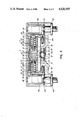
- FIG. 4 illustrates a protector as illustrated in FIGS. 1, 2 and 3 installed in a protector module.
- the module comprises two housings, a bottom housing 40 and a top housing 41.
- top housing 41 fits inside the bottom housing 40.
- a line terminal 42 extends through an aperture and is attached to a line contact member 43.
- Each line contact member is in the form of a Tee with the cross-bar 44 resting on the bottom wall of the bottom housing.
- the leg 45 extends upward spaced a short distance inside of a tubular structure 46 extending down from the top wall of the top housing.
- a ground terminal 47 is attached by a rivet 48 passing through the bottom wall of the bottom housing and fastened to a support and ground member 50.
- the support and ground member has a flat base 51 and arcuate walls 52, extending upward.
- the walls define a generally cylindrical position.
- the walls are divided into three sections by slots 53, to give a central section 54 and end sections 55.
- a similar support member is illustrated in FIG. 5.
- a three electrode gas tube protector asembly snaps into the support and ground member.
- the central section of the support and ground member makes contact with a central electrode of the gas tube protector.
- the end surfaces 31 of the head portions 24 of the contact members 20 are in contact with the line contact members 43 via the legs 45.
- the legs 45 are biased inward and are deflected outward on insertion of the gas tube protector assembly.
- Center section 54 of the support and ground member makes contact with the periphery of the central electrode 10.
- the inner cup 18 moves to bring the flange 22 into contact with the end surface of the support and ground member 50.
- each gap is usually at a sub-atmospheric pressure, with the electrodes sealed to the ceramic rings. If the seal breaks, the gaps become vented to atmosphere and the breakdown voltage rises to an unacceptable value.
- a back-up gap device is provided. In the example illustrated in FIG. 4, a back-up device is provided for each line and are indicated at 60.
- the back-up gap devices at 60 each comprise two electrodes 61 and 62 separated by and bonded to a disc 63 of insulating material.
- the disc has a central hole which defines a gap between the electrodes.
- the gap is arranged to break down at a voltage which is slightly higher than the breakdown voltage of the gaps 13 and 14.
- the back-up devices are held between the cross bars 44 of the line contact members 43 and the bottom 51 of the support and ground member 50.
- the protector as illustrated in FIGS. 1, 2 and 3 can also be used in an interface module, as described in application Ser. No. 630,880, filed July 13, 1984, in the names of the present assignee.
- FIG. 5 an exploded perspective view of an interface module as illustrated in the above referenced application, also shows a protector as in FIGS. 1, 2 and 3.
- the module has a base 60, which combines with a top, not shown, to form an enclosure.
- In the base are two slots 61 for line terminals and a slot 62 for a ground terminal.
- Two pillars 63 extend up from the inner bottom surface of the base, the pillars having opposed grooves 64 in which slides a contact member 65 for a modular jack.
- the base has an arcuate portion 66 at the jack position.
- Mounting posts 67, 68 extend up from the bottom surface for mounting and positioning of terminals in the housing.
- Each line terminal has a blade portion 71 which extends down through a slot 61.
- an L-shaped portion extends, comprising a support portion 72 extending generally normal to the blade portion, and a contact portion 73 extending normal to the support portion.
- the support portions 72 rest on ribs 74 on the bottom surface of the base 60, holes 69 allowing passage of the posts 67 and 68.
- the contact portions are adjacent the ends of the base, with the support portions extending towards each other.
- a ground terminal member 75 has a blade portion 76 which extends through slot 62 and a tubular protector holding portion 77 which is divided into three portions by slits 78. In position, the protector holding portion rests on top of the posts 67, and is located by holes 79 which fit over top portions 80 of the posts 68, the portions 80 being of smaller diameter than the lower parts of the posts. This maintains a gap between the portion 77 of the ground terminal member 75 and the line terminals 70.
- a protector Positioned between the support portions 72 of the line terminals and the protector holding portion 77 of the ground terminal are back-up protectors 81. The protectors rest in recesses 82 formed in the support portions 72. Positioned in the tubular protector holding portion 77 of the ground terminal 75 is a protector, indicated at 84, as illustrated in FIGS. 1, 2 and 3. To provide some contact resilience, spring contact members 85 are positioned on the contact portions 73 of the line terminals 70. The disc-like head portions 24 (FIG. 1) make contact with the spring contact members 85.
- the central electrode 10 of the protector 84 makes contact with the protector holding portion 77 of the ground terminal 75.
- the metal cups 17 are insulated from the protector holding portion 77 by the plastic tubes 16.
- Tabs 86 on the line terminals 70 provide for connection of line conductors 87 from the contact member 65.
Landscapes
- Fuses (AREA)
Abstract
Description
Claims (10)
Priority Applications (2)
| Application Number | Priority Date | Filing Date | Title |
|---|---|---|---|
| US06/714,501 US4626955A (en) | 1985-03-21 | 1985-03-21 | Three electrode gas tube protector |
| CA000485117A CA1257324A (en) | 1985-03-21 | 1985-06-25 | Three electrode gas tube protector |
Applications Claiming Priority (1)
| Application Number | Priority Date | Filing Date | Title |
|---|---|---|---|
| US06/714,501 US4626955A (en) | 1985-03-21 | 1985-03-21 | Three electrode gas tube protector |
Publications (1)
| Publication Number | Publication Date |
|---|---|
| US4626955A true US4626955A (en) | 1986-12-02 |
Family
ID=24870300
Family Applications (1)
| Application Number | Title | Priority Date | Filing Date |
|---|---|---|---|
| US06/714,501 Expired - Lifetime US4626955A (en) | 1985-03-21 | 1985-03-21 | Three electrode gas tube protector |
Country Status (2)
| Country | Link |
|---|---|
| US (1) | US4626955A (en) |
| CA (1) | CA1257324A (en) |
Cited By (10)
| Publication number | Priority date | Publication date | Assignee | Title |
|---|---|---|---|---|
| US4742541A (en) * | 1983-10-25 | 1988-05-03 | Northern Telecom Limited | Telecommunications interface with protector modules |
| US4796150A (en) * | 1987-04-16 | 1989-01-03 | American Telephone And Telegraph Company, At&T Bell Laboratories | Telecommunication protector unit with pivotal surge protector |
| US4858059A (en) * | 1988-09-19 | 1989-08-15 | Masahiko Okura | Short-circuit device of a gas-filled triple-pole discharge-tube type arrester for telephone line use |
| US5289154A (en) * | 1993-04-21 | 1994-02-22 | Davis Kenneth S | Fuse cutout assembly and method |
| US5721773A (en) * | 1995-03-30 | 1998-02-24 | Lucent-Technologies Inc. | Lightning protected maintenance termaination unit |
| US20080204963A1 (en) * | 2007-02-28 | 2008-08-28 | Baker Scott K | Overvoltage protection plug |
| USD591691S1 (en) | 2007-02-28 | 2009-05-05 | Adc Telecommunications, Inc. | Overvoltage protection plug |
| US20090296303A1 (en) * | 2008-05-27 | 2009-12-03 | Petersen Cyle D | Overvoltage Protection Plug |
| USD620896S1 (en) | 2008-05-27 | 2010-08-03 | Adc Telecommunications, Inc. | Overvoltage protection plug |
| US7946863B2 (en) | 2008-04-25 | 2011-05-24 | Adc Telecommunications, Inc. | Circuit protection block |
Citations (3)
| Publication number | Priority date | Publication date | Assignee | Title |
|---|---|---|---|---|
| US4015228A (en) * | 1974-06-10 | 1977-03-29 | Matsushita Electric Industrial Co., Ltd. | Surge absorber |
| US4056840A (en) * | 1976-05-12 | 1977-11-01 | Reliable Electric Company | Line protector for communications circuit |
| US4074337A (en) * | 1976-10-27 | 1978-02-14 | Northern Telecom Limited | Protector for telecommunication lines |
-
1985
- 1985-03-21 US US06/714,501 patent/US4626955A/en not_active Expired - Lifetime
- 1985-06-25 CA CA000485117A patent/CA1257324A/en not_active Expired
Patent Citations (3)
| Publication number | Priority date | Publication date | Assignee | Title |
|---|---|---|---|---|
| US4015228A (en) * | 1974-06-10 | 1977-03-29 | Matsushita Electric Industrial Co., Ltd. | Surge absorber |
| US4056840A (en) * | 1976-05-12 | 1977-11-01 | Reliable Electric Company | Line protector for communications circuit |
| US4074337A (en) * | 1976-10-27 | 1978-02-14 | Northern Telecom Limited | Protector for telecommunication lines |
Cited By (14)
| Publication number | Priority date | Publication date | Assignee | Title |
|---|---|---|---|---|
| US4742541A (en) * | 1983-10-25 | 1988-05-03 | Northern Telecom Limited | Telecommunications interface with protector modules |
| US4796150A (en) * | 1987-04-16 | 1989-01-03 | American Telephone And Telegraph Company, At&T Bell Laboratories | Telecommunication protector unit with pivotal surge protector |
| US4858059A (en) * | 1988-09-19 | 1989-08-15 | Masahiko Okura | Short-circuit device of a gas-filled triple-pole discharge-tube type arrester for telephone line use |
| US5289154A (en) * | 1993-04-21 | 1994-02-22 | Davis Kenneth S | Fuse cutout assembly and method |
| WO1994024688A1 (en) * | 1993-04-21 | 1994-10-27 | Davis Kenneth S | Fuse cutout assembly and method |
| US5721773A (en) * | 1995-03-30 | 1998-02-24 | Lucent-Technologies Inc. | Lightning protected maintenance termaination unit |
| US20080204963A1 (en) * | 2007-02-28 | 2008-08-28 | Baker Scott K | Overvoltage protection plug |
| USD591691S1 (en) | 2007-02-28 | 2009-05-05 | Adc Telecommunications, Inc. | Overvoltage protection plug |
| US8064182B2 (en) | 2007-02-28 | 2011-11-22 | Adc Telecommunications, Inc. | Overvoltage protection plug |
| US9865995B2 (en) | 2007-02-28 | 2018-01-09 | Commscope Technologies Llc | Overvoltage protection plug |
| US7946863B2 (en) | 2008-04-25 | 2011-05-24 | Adc Telecommunications, Inc. | Circuit protection block |
| US20090296303A1 (en) * | 2008-05-27 | 2009-12-03 | Petersen Cyle D | Overvoltage Protection Plug |
| USD620896S1 (en) | 2008-05-27 | 2010-08-03 | Adc Telecommunications, Inc. | Overvoltage protection plug |
| US8411404B2 (en) | 2008-05-27 | 2013-04-02 | Adc Telecommunications, Inc. | Overvoltage protection plug |
Also Published As
| Publication number | Publication date |
|---|---|
| CA1257324A (en) | 1989-07-11 |
Similar Documents
| Publication | Publication Date | Title |
|---|---|---|
| US5523916A (en) | Surge arrester with thermal overload protection | |
| US4493003A (en) | Surge arrester assembly | |
| US5224013A (en) | Miniature station protector modules | |
| US4056840A (en) | Line protector for communications circuit | |
| US4161762A (en) | Gas tube arrester protector and method of assembling the protector | |
| US3813577A (en) | Overvoltage protection apparatus having fusible ring and short circuit means operated thereby | |
| US4086648A (en) | Protector module | |
| US5172296A (en) | Solid state overvoltage protector assembly | |
| US4734823A (en) | Fault current interrupter and explosive disconnector for surge arrester | |
| US4613732A (en) | Interface module with modular jack for telecommunications systems | |
| US3818271A (en) | Line connector for a communications circuit | |
| US3254181A (en) | Mounting having short circuit means for communication line protector | |
| US4626955A (en) | Three electrode gas tube protector | |
| US5224012A (en) | Solid state station protectors | |
| US3254179A (en) | Mounting for communication line protector | |
| US4208694A (en) | Line protector | |
| US4594635A (en) | Overload protector for communication systems | |
| US4736269A (en) | Voltage surge limiter with grounding assembly | |
| US4074337A (en) | Protector for telecommunication lines | |
| US4866562A (en) | Self-contained air gap assembly | |
| US4584624A (en) | Station protector for telecommunications systems | |
| US4675778A (en) | Overload protector for communications systems | |
| US4188561A (en) | Station protector spark gap applique | |
| US5282109A (en) | Back-up air gaps | |
| US4851946A (en) | Lightning arrester |
Legal Events
| Date | Code | Title | Description |
|---|---|---|---|
| AS | Assignment |
Owner name: NORTHERN TELECOM LIMITED, P.O. BOX 6123, STATION A Free format text: ASSIGNMENT OF ASSIGNORS INTEREST.;ASSIGNOR:CWIRZEN, CASIMIR Z.;REEL/FRAME:004386/0700 Effective date: 19850226 |
|
| STCF | Information on status: patent grant |
Free format text: PATENTED CASE |
|
| FEPP | Fee payment procedure |
Free format text: PAYOR NUMBER ASSIGNED (ORIGINAL EVENT CODE: ASPN); ENTITY STATUS OF PATENT OWNER: LARGE ENTITY |
|
| FPAY | Fee payment |
Year of fee payment: 4 |
|
| FPAY | Fee payment |
Year of fee payment: 8 |
|
| FPAY | Fee payment |
Year of fee payment: 12 |
|
| AS | Assignment |
Owner name: NORTEL NETWORKS CORPORATION, CANADA Free format text: CHANGE OF NAME;ASSIGNOR:NORTHERN TELECOM LIMITED;REEL/FRAME:010567/0001 Effective date: 19990429 |
|
| AS | Assignment |
Owner name: NORTEL NETWORKS LIMITED, CANADA Free format text: CHANGE OF NAME;ASSIGNOR:NORTEL NETWORKS CORPORATION;REEL/FRAME:011195/0706 Effective date: 20000830 Owner name: NORTEL NETWORKS LIMITED,CANADA Free format text: CHANGE OF NAME;ASSIGNOR:NORTEL NETWORKS CORPORATION;REEL/FRAME:011195/0706 Effective date: 20000830 |