US4594635A - Overload protector for communication systems - Google Patents
Overload protector for communication systems Download PDFInfo
- Publication number
- US4594635A US4594635A US06/643,406 US64340684A US4594635A US 4594635 A US4594635 A US 4594635A US 64340684 A US64340684 A US 64340684A US 4594635 A US4594635 A US 4594635A
- Authority
- US
- United States
- Prior art keywords
- protector
- bracket
- line
- extension
- housing
- Prior art date
- Legal status (The legal status is an assumption and is not a legal conclusion. Google has not performed a legal analysis and makes no representation as to the accuracy of the status listed.)
- Expired - Lifetime
Links
Images


Classifications
-
- H—ELECTRICITY
- H01—ELECTRIC ELEMENTS
- H01T—SPARK GAPS; OVERVOLTAGE ARRESTERS USING SPARK GAPS; SPARKING PLUGS; CORONA DEVICES; GENERATING IONS TO BE INTRODUCED INTO NON-ENCLOSED GASES
- H01T4/00—Overvoltage arresters using spark gaps
- H01T4/06—Mounting arrangements for a plurality of overvoltage arresters
Definitions
- This invention relates to an overload protector for systems, particularly an overvoltage and overcurrent protector, for telephone lines.
- Protectors are usually provided, at Central Office locations to protect electrical:and electronic items against power surges, arriving over the telephone lines.
- Protectors are usually mounted on a connector or other device, which also carries a test facility and a cross-connect facility. In such a connector these facilities are often referred to as "fields", that is, a protector field, a test field and a cross-connect field.
- the present invention combines the test facility with the protector facility.
- Protectors for protection against overvoltage conditions are generally of two basic forms, a gas tube protector in which two electrodes are sealed into a support body with a gap between them, at a sub-atmospheric pressure, and a carbon block protector which has two carbon electrodes spaced apart to form a gap at atmospheric pressure.
- Wnile gas tube and carbon block protectors break down to give either a dead short or a very low breakdown voltage, which condition is readily detected, a gas tube protector can also break down by venting, that is leakage of air into the gap. This raises the breakdown voltage, which is not normally detectable. This is undesirable in that a sufficiently low breakdown voltage is not provided, to protect equipment. It is therefore normal to provide a back-up gap device to take over the protection when the main gap is faulty.
- the back up gap is arranged to fairly rapidly break down to a short or very low value, which is detectable.
- the present invention enables either type of protector to be used.
- a heat sensitive device can be provided for protection against overcurrent conditions, or where overvoltage conditions persist.
- the present invention provides for such a heat sensitive device, if desired.
- the present invention provides a protector assembly having line terminals or pins and a ground terminal or pin in the base, with a line bracket forming part of the line circuit between the Central Office terminal and the outside or line terminal.
- the line bracket extends up to the top or outer end of the housing, where an aperture provides access to the line bracket for testing.
- a back-up gap device may be positioned between the line bracket and a ground bracket at the top or outer end.
- the line circuit may include a heat coil assembly.
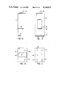
- FIG. 1 is a side view of one form of protector assembly with the side wall removed to show interior details, in the direction of arrow A in FIG. 2;
- FIG. 2 is a front view of the assembly of FIG. 1 with the front wall removed for most of the assembly length to show interior details, in the direction of arrow B in FIG. 1;
- FIGS. 3, 4 and 5 are cross-sections on the lines III--, IV--IV and V--V respectively of FIG. 1;
- FIG. 6 is a side view of the ground member of the assembly
- FIG. 7 is a top view of the ground member of FIG. 6, in the direction of arrow C;
- FIG. 8 is a side view of one of the line brackets of the assembly.
- FIG. 9 is a front view of the line bracket in FIG. 8;
- FIG. 10 is a top plan view of the protector assembly in FIG. 1;
- FIG. 11 is a bottom plan view of the protector assembly in FIG. 1;
- FIGS. 12 and 13 are partial views, similar to the top and bottom parts respectively of FIG. 2, illustrating modifications.
- the protector module or assembly 10 illustrated has two protectors, of the gas tube type, a protector between each line and ground.
- the protectors are indicated at 11 and 11a.
- the various parts are assembled and mounted within a molded electrically insulating plastic housing 12 with a molded insulating base 13.
- the line pins 14, 14a and 15, 15a and a ground pin 16 are mounted in the base.
- Pin 14 is the central office pin or terminal and the pin 15 is the outside plant or line pin or terminal, pins 14 and 15 forming a pair.
- the pin 14 is attached to the base 13, as by swaging or ultrasonic welding, the outer end of the pin being adapted to fit a terminal in a connector block, and the inner end 18 projecting above the inner surface of the base for attachment of a lead from a heat coil.
- the plastic housing 12 and base 13 are molded with formations which act to position various items of the assembly.
- the base 13 has two hollow bosses 19, 19a extending up from its inner surface.
- a heat coil unit 20, 20a rests on each boss.
- a heat coil unit comprises a spool 21 having a flat flange 22 at its inner end and a hollow annular flange 23 at its outer end. The flange 23 fits over the related boss 19 which positions the heat coil and prevents sideways movement. The boss also opposes the axial force on the heat coil and aids assembly.
- Within the spool 21 is a shaft 24.
- the shaft 24 is soldered to the spool 21, but under overcurrent conditions, when the solder is melted, the shaft is free to slide axially in the bore of the spool.
- the lower or outer end of the shaft is accommodated by a pocket or recess in the boss.
- the shaft 24 extends beyond flange 22 and bears against a projecting pin 25 extending from the end of one of the electrodes of the protector 11.
- a flange 26 is formed on the shaft 24 at its inner end to limit movement towards the base.
- the outside plant pin 15 extends through the base 13, being inserted from the outside of the base and positioned axially by a shoulder 30 which is positioned against the surface of a recess in the outer surface of the base.
- the outer end of pin 15 is adapted to fit a terminal in a connector block and the inner end 31 extends a short distance above the inner surface of the base.
- a line bracket 32 is attached to the inner end 31 of pin 15.
- the line bracket 32 extends the length of the housing 12, positioned against a back wall of the housing. At its lower or inner end a leg 33 extends normal to the length of the bracket. The leg has two slots extending in from its free end. These slots are seen at 34 in FIG. 3.
- the inner end of the pin 15 is a snap fit in one of the slots 34. Two slots are provided so that only one form of bracket is required, the pin 15 being asymmetric relative to the bracket, and the particular slot used depends upon which side of the protector assembly the bracket is in.
- the fit of the pin 15 is enhanced by providing an annular groove on the inner end of the pin.
- the pin 15 can be permanently attached, as by swaging, with holes instead of slots 34 being provided.
- the bracket 32 has a further leg 35 extending normal to the length of the leg. Leg 35 fits in a recess formed in the end of the housing 12. At an intermediate position a third leg 36 extends normal to the length of the bracket. Leg 36 has a slot 37, seen in FIG. 4, which is a close sliding fit on the shaft 24 at a position spaced from the flange 26 and between flange 26 and the spool flange 22. Leg 36, by means of the slot 37, engages the shaft 24 in a manner that provides an electrical contact between the leg 36 and shaft 24, but which permits axial movement of the shaft 24.
- the spool 21 and the shaft 24 are secured together by a low melting point solder, such as a 49.5% Bi, 27.5% Pb, 13.1% Sn, 10.1% Cd solder, to form a rigid assembly.
- a low melting point solder such as a 49.5% Bi, 27.5% Pb, 13.1% Sn, 10.1% Cd solder
- a length of insulated wire is wrapped round the spool, as indicated at 40, with one end of the wire attached to a flange of the spool, normally the flange 23. The other end of the wire is attached to the end 18 of the central office terminal 14.
- the ground assembly comprises a ground bracket 45 which extends along in the housing 12 on the opposite wall to the line brackets 32 and 32a.
- a leg 46 extends normal to the length of the bracket, the leg being attached to the inner end of the ground pin 16.
- the ground bracket has a flange or leg 47 which extends over both protector units 11 and 11a.
- Four narrow arcuate extensions 48 extend towards the lower or inner end of the ground bracket. The extensions 48 engage the outside of cups 49, 49a which are positioned over the protector units 11 and 11a.
- Compression springs 50, 50a are positioned between the lower surface of the flange 47 and the upper ends of the cups 49, 49a. Between the flange 47 and the legs 35 and 35a are positioned separating members 51 and 51a. Separating members 51 and 51a, in the example illustrated are back-up protector members, which become effective at a voltage at least slightly higher than the voltage at which the main protectors 11 and 11a become effective.
- the back-up protectors can be of a back-up gap form, of a solid state form or other as desired.
- a handle 55 extends from the end of the casing, for pulling out the protector module or assembly, and for insertion of the module.
- the casing extends at 56 for back and front walls, and in each wall there are two apertures 57.
- FIG. 11 is a view of the base of the protector assembly and the two sets of line pins 14, 14a and 15, 15a are seen and also ground pin 16.
- the protector assembly is assembled as follows.
- the heat coil assembly of spool 20 and wire winding 40 and shaft 24 are positioned over a boss 19 and the wire end attached, as by welding or soldering, to the pin 14.
- Pin 15 is inserted through the base and the line bracket 32 attached by engaging the leg 33 on to the end 31 of the pin 15.
- the leg 36 engages with the shaft 24.
- the ground pin 16 with the ground bracket 45 attached is inserted into the base, with protectors 11 and 11a and springs 50 and 50a in position, plus cups 49, 49a.
- the cups 49, 49a are tilted slightly to rest on lateral extensions 45a extending from the ground bracket 45, to retain the cups and springs in positions while inserting the ground bracket.
- the pins 25 and 25a from the protectors 11 and 11a rest on the flanges 26, 26a of the shafts 24, 24a.
- the ground brackets and pin 16 are pushed to collapse the springs 50, 50a and the back-up gap items 51 and 51a inserted between the flange 47 and legs 35 and 35a.
- the ground bracket is then released to grip the items 51 and 51a. This assembly procedure would require modifying if the pins 15 were attached by swaging.
- the arrangement operates in a conventional manner. Overvoltage surges occurring on either, or both, telephone lines will normally cause a spark discharge across the gap in one or both protectors 11 and 11a, to ground, via cups 49, 49a extensions 48 and 9round bracket 45 to the ground pin.
- the wire windings 40, 40a cause melting of the solder holding the shafts 24, 24a to the spools 21, 21a. This permits the shafts to be pushed down, together with the protectors 11, 11a and cups 49, 49a under the pressure of the springs 50, 50a.
- the edges of the cups engage the legs 36, 36a of the line brackets, grounding the lines.
- One or both of the heat coils may experience melting of the solder depending upon whether the overload current is on one or both lines.
- the protector assembly has been described with the use of gas tube protectors at 11 and 11a, and with back-up gap members 51, 51a. If carbon block protectors are used at 11, 11a, or any other form of protector not requiring a back-up member, then members 51, 51a can be omitted. Carbon block protectors are normally of the same overall dimensions as gas tube protectors and are a straight forward replacement. To avoid changing other parts of the structure when back-up members are not used, separating members in the form of spacer members are used, indicated at 60, 60a, to replace the members 51, 51a. The spacers 60, 60a are of insulating material.
- back-up member 51, 51a can vary widely, and also its relationship with the primary gap can be varied, depending upon the particular relative characteristics of the member 51, 51a and the primary gap in the protector 11, 11a.
- a further modification is the omission of the heat coil unit 20, 20a.
- the heat coil unit can be replaced by a spacer. This is illustrated in Figure 13, where spacers 61, 61a are shown. In this example the spacers replace the spool 21, 21a and the shaft 24, 24a, with the leg 36, 36a, of the line bracket 32, 32a, engaging with an extension 62, 62a on the spacer 61, 61a.
- a spacer when a spacer is used, instead of a heat coil, then provision must be made to shunt the related pair of terminals, i.e. terminals 14 and 15 and terminals 14a and 15a. This can be done by making the spacer of electrically conductive material and connecting the spacer to the terminals, or by providing an electrical shunt in the base to directly connect the terminals of a pair.
- the internal surface of the housing at the top or outer end is formed with shallow concave recesses 63, 63a.
- the legs 35, 35a of the line brackets have a domed portion 64, 64a which rest in the recesses 63, 63a.
- Domed portions 65, 65a are also formed in the flange or leg 47 of the ground bracket 45. These domed portions extend away from each other when the line brackets and ground bracket are assembled in the unit and the back-up members 51, 51a have convex outer surfaces which sit in the opposed domed portions, giving a good electrical contact and also providing positioning of the members.
- the protector unit or assembly of the present invention can be used to replace other protector units, providing a front test facility.
- a protector unit can contain only one protector, but normally two protectors are provided.
Landscapes
- Emergency Protection Circuit Devices (AREA)
Abstract
Description
Claims (15)
Priority Applications (2)
| Application Number | Priority Date | Filing Date | Title |
|---|---|---|---|
| US06/643,406 US4594635A (en) | 1984-08-23 | 1984-08-23 | Overload protector for communication systems |
| CA000467518A CA1232320A (en) | 1984-08-23 | 1984-11-09 | Overload protector for communication systems |
Applications Claiming Priority (1)
| Application Number | Priority Date | Filing Date | Title |
|---|---|---|---|
| US06/643,406 US4594635A (en) | 1984-08-23 | 1984-08-23 | Overload protector for communication systems |
Publications (1)
| Publication Number | Publication Date |
|---|---|
| US4594635A true US4594635A (en) | 1986-06-10 |
Family
ID=24580684
Family Applications (1)
| Application Number | Title | Priority Date | Filing Date |
|---|---|---|---|
| US06/643,406 Expired - Lifetime US4594635A (en) | 1984-08-23 | 1984-08-23 | Overload protector for communication systems |
Country Status (2)
| Country | Link |
|---|---|
| US (1) | US4594635A (en) |
| CA (1) | CA1232320A (en) |
Cited By (15)
| Publication number | Priority date | Publication date | Assignee | Title |
|---|---|---|---|---|
| US4796150A (en) * | 1987-04-16 | 1989-01-03 | American Telephone And Telegraph Company, At&T Bell Laboratories | Telecommunication protector unit with pivotal surge protector |
| US4817270A (en) * | 1986-04-21 | 1989-04-04 | Northern Telecom Limited | Method of manufacturing a heat coil assembly for a protector unit |
| US4937699A (en) * | 1988-03-23 | 1990-06-26 | Illinois Tool Works, Inc. | Frequency dependent fuse for a telephone circuit or the like |
| US5025345A (en) * | 1987-02-24 | 1991-06-18 | Northern Telecom Limited | Overload protector module and building entry protector with integrally molded modular jack |
| US5034846A (en) * | 1989-09-11 | 1991-07-23 | Donald E. Hodge | Plug protector |
| US5101317A (en) * | 1989-06-08 | 1992-03-31 | Northern Telecom Limited | Overload protector for telecommunications systems |
| US6118664A (en) * | 1999-01-13 | 2000-09-12 | Lucent Technologies, Inc. | Handle for plug-in protectors |
| US6531717B1 (en) | 1999-03-01 | 2003-03-11 | Teccor Electronics, L.P. | Very low voltage actuated thyristor with centrally-located offset buried region |
| US6956248B2 (en) | 1999-03-01 | 2005-10-18 | Teccor Electronics, Lp | Semiconductor device for low voltage protection with low capacitance |
| US20080204963A1 (en) * | 2007-02-28 | 2008-08-28 | Baker Scott K | Overvoltage protection plug |
| USD591691S1 (en) | 2007-02-28 | 2009-05-05 | Adc Telecommunications, Inc. | Overvoltage protection plug |
| US20090269954A1 (en) * | 2008-04-25 | 2009-10-29 | Vern Loch | Circuit protection block |
| US20090296303A1 (en) * | 2008-05-27 | 2009-12-03 | Petersen Cyle D | Overvoltage Protection Plug |
| USD620896S1 (en) | 2008-05-27 | 2010-08-03 | Adc Telecommunications, Inc. | Overvoltage protection plug |
| CN101752859B (en) * | 2008-12-05 | 2012-05-16 | 沈阳铁路信号有限责任公司 | Surge protector with test pin |
Citations (2)
| Publication number | Priority date | Publication date | Assignee | Title |
|---|---|---|---|---|
| US3849750A (en) * | 1974-01-02 | 1974-11-19 | Reliable Electric Co | Line protector for a communication circuit |
| US4502088A (en) * | 1983-03-18 | 1985-02-26 | Reliance Electric Company | Line protector for a communications circuit |
-
1984
- 1984-08-23 US US06/643,406 patent/US4594635A/en not_active Expired - Lifetime
- 1984-11-09 CA CA000467518A patent/CA1232320A/en not_active Expired
Patent Citations (2)
| Publication number | Priority date | Publication date | Assignee | Title |
|---|---|---|---|---|
| US3849750A (en) * | 1974-01-02 | 1974-11-19 | Reliable Electric Co | Line protector for a communication circuit |
| US4502088A (en) * | 1983-03-18 | 1985-02-26 | Reliance Electric Company | Line protector for a communications circuit |
Cited By (20)
| Publication number | Priority date | Publication date | Assignee | Title |
|---|---|---|---|---|
| US4817270A (en) * | 1986-04-21 | 1989-04-04 | Northern Telecom Limited | Method of manufacturing a heat coil assembly for a protector unit |
| US5025345A (en) * | 1987-02-24 | 1991-06-18 | Northern Telecom Limited | Overload protector module and building entry protector with integrally molded modular jack |
| US4796150A (en) * | 1987-04-16 | 1989-01-03 | American Telephone And Telegraph Company, At&T Bell Laboratories | Telecommunication protector unit with pivotal surge protector |
| US4937699A (en) * | 1988-03-23 | 1990-06-26 | Illinois Tool Works, Inc. | Frequency dependent fuse for a telephone circuit or the like |
| US5101317A (en) * | 1989-06-08 | 1992-03-31 | Northern Telecom Limited | Overload protector for telecommunications systems |
| US5034846A (en) * | 1989-09-11 | 1991-07-23 | Donald E. Hodge | Plug protector |
| US6118664A (en) * | 1999-01-13 | 2000-09-12 | Lucent Technologies, Inc. | Handle for plug-in protectors |
| US6531717B1 (en) | 1999-03-01 | 2003-03-11 | Teccor Electronics, L.P. | Very low voltage actuated thyristor with centrally-located offset buried region |
| US6696709B2 (en) | 1999-03-01 | 2004-02-24 | Teccor Electronics, Lp | Low voltage protection module |
| US6956248B2 (en) | 1999-03-01 | 2005-10-18 | Teccor Electronics, Lp | Semiconductor device for low voltage protection with low capacitance |
| US20080204963A1 (en) * | 2007-02-28 | 2008-08-28 | Baker Scott K | Overvoltage protection plug |
| USD591691S1 (en) | 2007-02-28 | 2009-05-05 | Adc Telecommunications, Inc. | Overvoltage protection plug |
| US8064182B2 (en) | 2007-02-28 | 2011-11-22 | Adc Telecommunications, Inc. | Overvoltage protection plug |
| US9865995B2 (en) | 2007-02-28 | 2018-01-09 | Commscope Technologies Llc | Overvoltage protection plug |
| US20090269954A1 (en) * | 2008-04-25 | 2009-10-29 | Vern Loch | Circuit protection block |
| US7946863B2 (en) | 2008-04-25 | 2011-05-24 | Adc Telecommunications, Inc. | Circuit protection block |
| US20090296303A1 (en) * | 2008-05-27 | 2009-12-03 | Petersen Cyle D | Overvoltage Protection Plug |
| USD620896S1 (en) | 2008-05-27 | 2010-08-03 | Adc Telecommunications, Inc. | Overvoltage protection plug |
| US8411404B2 (en) | 2008-05-27 | 2013-04-02 | Adc Telecommunications, Inc. | Overvoltage protection plug |
| CN101752859B (en) * | 2008-12-05 | 2012-05-16 | 沈阳铁路信号有限责任公司 | Surge protector with test pin |
Also Published As
| Publication number | Publication date |
|---|---|
| CA1232320A (en) | 1988-02-02 |
Similar Documents
| Publication | Publication Date | Title |
|---|---|---|
| US4876621A (en) | Line protector for a communications circuit | |
| US4594635A (en) | Overload protector for communication systems | |
| US3975664A (en) | Line protector for communication circuit | |
| CA1090399A (en) | Line fault protector module having a fusible element controlling a grounding circuit | |
| US3849750A (en) | Line protector for a communication circuit | |
| US4161762A (en) | Gas tube arrester protector and method of assembling the protector | |
| US4502088A (en) | Line protector for a communications circuit | |
| US4958253A (en) | Line protector for a communications circuit | |
| US5224013A (en) | Miniature station protector modules | |
| US3818271A (en) | Line connector for a communications circuit | |
| US3743888A (en) | Line protector for a communication circuit | |
| US4168515A (en) | Line protector for a communications circuit | |
| US4424546A (en) | Miniature central office surge protectors | |
| US5224012A (en) | Solid state station protectors | |
| MXPA02010616A (en) | Central office surge protector with interacting varistors. | |
| US5384679A (en) | Solid state surge protectors | |
| US4074337A (en) | Protector for telecommunication lines | |
| US4307430A (en) | Protector device for telecommunications circuits | |
| US4447848A (en) | Telephone surge protector and housings therefor | |
| GB2193396A (en) | Three element gas tube protector module | |
| US5282109A (en) | Back-up air gaps | |
| US4458288A (en) | Electrical protective devices | |
| EP0475954B1 (en) | An overload protector for telecommunications systems | |
| US4434449A (en) | Protector unit for telecommunications circuits | |
| CA1257324A (en) | Three electrode gas tube protector |
Legal Events
| Date | Code | Title | Description |
|---|---|---|---|
| AS | Assignment |
Owner name: NORTHERN TELECOM LIMITED, P.O. BOX 6123, STATION A Free format text: ASSIGNMENT OF ASSIGNORS INTEREST.;ASSIGNORS:SCHEITHAUER, ERIC A.;JAYCOX, DONALD F.;REEL/FRAME:004304/0803 Effective date: 19840723 |
|
| STCF | Information on status: patent grant |
Free format text: PATENTED CASE |
|
| FPAY | Fee payment |
Year of fee payment: 4 |
|
| FPAY | Fee payment |
Year of fee payment: 8 |
|
| FPAY | Fee payment |
Year of fee payment: 12 |
|
| AS | Assignment |
Owner name: NORTEL NETWORKS CORPORATION, CANADA Free format text: CHANGE OF NAME;ASSIGNOR:NORTHERN TELECOM LIMITED;REEL/FRAME:010567/0001 Effective date: 19990429 |
|
| AS | Assignment |
Owner name: NORTEL NETWORKS LIMITED, CANADA Free format text: CHANGE OF NAME;ASSIGNOR:NORTEL NETWORKS CORPORATION;REEL/FRAME:011195/0706 Effective date: 20000830 Owner name: NORTEL NETWORKS LIMITED,CANADA Free format text: CHANGE OF NAME;ASSIGNOR:NORTEL NETWORKS CORPORATION;REEL/FRAME:011195/0706 Effective date: 20000830 |