US462533A - Walking and riding cultivator - Google Patents
Walking and riding cultivator Download PDFInfo
- Publication number
- US462533A US462533A US462533DA US462533A US 462533 A US462533 A US 462533A US 462533D A US462533D A US 462533DA US 462533 A US462533 A US 462533A
- Authority
- US
- United States
- Prior art keywords
- shank
- cultivator
- bar
- frames
- stock
- Prior art date
- Legal status (The legal status is an assumption and is not a legal conclusion. Google has not performed a legal analysis and makes no representation as to the accuracy of the status listed.)
- Expired - Lifetime
Links
- 210000001699 lower leg Anatomy 0.000 description 58
- 210000003414 Extremities Anatomy 0.000 description 12
- 238000010276 construction Methods 0.000 description 2
- 230000000875 corresponding Effects 0.000 description 2
- 239000002184 metal Substances 0.000 description 2
- 230000001105 regulatory Effects 0.000 description 2
Images


Classifications
-
- A—HUMAN NECESSITIES
- A01—AGRICULTURE; FORESTRY; ANIMAL HUSBANDRY; HUNTING; TRAPPING; FISHING
- A01B—SOIL WORKING IN AGRICULTURE OR FORESTRY; PARTS, DETAILS, OR ACCESSORIES OF AGRICULTURAL MACHINES OR IMPLEMENTS, IN GENERAL
- A01B39/00—Other machines specially adapted for working soil on which crops are growing
- A01B39/02—Other machines specially adapted for working soil on which crops are growing with non-rotating tools
Definitions
- BosIL FRANCIS Cou- LOMB of Clifton, in the county of Iroquois and State of Illinois, have invented a new and useful Improvement in alking and Riding Cultivators, of which the following is a full, clear, and exact description.
- My invention relates to an improvementin cultivators, and has for its object to provide a cultivator capable of use either as a riding or a walking implement; and a furtherobject of the invention is to provide swinging frames and shanks pivoted in the frames adapted to receive various styles of cultivating blades, shovels, or teeth, and to so construct and hang the frames and locate the shanks in the frames that the frames may be carried forward or outward in a horizontal line without lifting the blades, shovels, or teeth from the ground or pressing them farther in the same, and whereby also any degree of inclination may be given to the shovels, blades, or teeth that the character of the ground and the plants to be cultivated may require.
- the invention consists in the novel con struction and combination of the several parts, as Will be hereinafter fully set forth, and pointed out in the claims.
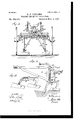
- Figure 1 is a plan view of the implement.
- Fig. 2 is a longitudinal vertical section taken through the same at one side of the central fixed frame.
- Fig. 3 is a front elevation of the implement, the tongue being in sect-ion.
- Fig. at is a side elevation of one of the swinging frames removed, illustrating the application thereto of a yoke carrying a shovel and a blade.
- Fig. 5 is a perspective view of the yoke shown in Fig. 4, illustrating the attachment thereto of two blades.
- Fig. 6 is a front elevation of pulveriZing-cultivators, and
- Fig. 7 is a section taken on the line 7 7 of Fig. 6.
- Fig. 8 is a rear view of pulverizing-knife blades
- Fig. 9 is a section taken upon the line 9 9 of Fig. 8.
- Fig. 10 is a front elevation of plain harrow-teeth
- Fig. 11 is a section on the line 11 11 of Fig. 10.
- Fig. 12
- Fig. 13 is a section taken upon the line 13 13 of Fig. 12.
- Fig. let is a side elevation of a pulverizing-disk attachment.
- Fig. 15 is a plan View of such attachment.
- Fig. 16 illustrates the shank for attaching shovels or gopherblades, and
- Fig. 17 is a bottom plan View of a portion of the shank.
- the main or fixed frame of the implement consists of a tongue 10, to the under side of which near the rear end a beam 11 is securely bolted, and at each side of the tongue diagonal beams 12 and 1-3 are attached at their inner ends, which beams extend rearward in opposite directions over and in engagement with the upper face of the beam 11.
- the beams 11, 12, and 13, the tongue 10, and an arched axle 14: may be said to constitute the fixed frame of the implement.
- the axle 1i .wheels 15 are loosely mounted, which wheels are of considerable diameter, whereby the main frame is elevated some distance from the ground.
- Seat-sup ports 16 are preferably attached to the side beams 12 and 13, and the seat 17 is adjustably arranged upon said supports in any suitable or approved manner.
- An equalizing-bar 18 is pivotally attached to the lower face of the tongue 10, and the said equalizing-bar is provided at each extremity with a downwardly-extending platelink 19, provided with a series of apertures 20, and the whiffletrees 21 are attached to the plate-links 19 by passing suitable fastening devices through the apertures 20.
- the burden of the draft maybe regulated, and the draft is at all times directly from the axle, as the platelinks 19 are connected by rod-links 22 or their equivalents to the axle near the wheels 15, as illustrated in Figs. 1 and 2, and if in practice it is found desirable brace-rods 23, united by turn-buckles 21-, may be em ployed to connect the central portion of the equalizing-bar to the axle, as is illustrated in Fig. 3.
- a swinging frame A is adapted to be located at each side of the main frame.
- swinging frame is preferably made entirely of metal and comprises an upper horizontal bar 25, terminating at its forward end in a round threaded surface 25 and at its rear end in a hook 25. Between the center and the rear end of the bar the upper end of a vertical bar 26 is securely bolted, and a diagonal bar 27 connects the lower end of the vertical bar 26 with the forward portion of the upper bar 25. The lower end of the diagonal bar 27 .is carried horizontally beyond the rear edge of the vertical bar 26, and in the horizontal portion of the diagonal bar 27 a socket 28 is produced, while an aligning socket 29 is likewise formed in or upon the upper bar 25 of the swinging frame, as is best shown in the detail view of said frame in Fig. 4.
- the sockets 28 and 29 are adapted to receive the vertical member of an angular stock or shank 30, to the lower end of which stock or shank the attachments for cultivating the ground and plants are ad justably secu red.
- the stock or shank 30 is loosely mounted in the sockets 28 and 29, so that it is capable of turning therein, and the horizontal member of the stock or shank is located at the upper portion thereof and extends over the upper bar 25 of the swinging frame.
- the yokebar has produced at its extremities slots 35, and eyebolts 36 are adjustably secured in said slots, and the hooks 25 of the frames are passed through the eyes of said bolts.
- a twin hook 37, or the equivalent thereof, is bolted to the central portion of the under side of the yoke-bar 34, and brace-rods 38 are attached to said hooks at their upper ends, the lower ends of the brace-rods being secured to the horizontal extremities of the diagonal bars 27 of the swinging frames.
- the horizontal members of the stocks or shanks 30 are connected by links 39 and turn-buckles 40 to the under face of the tongue 10 at or near its inner end, and the yoke-bar 34 may be connected by chain or otherwise to the tongue if in practice it is found desirable.
- the swinging frames A may be elevated or lowered, as occasion may demand, which action is accomplished through the medium of angle-levers 41, pivoted upon the diagonal beams 12 and 13 of the fixed or main frame within convenient reach of the drivers seat, the said. angle-levers being provided with the usual thumb-latches 42 for engagement with racks 43, and the lower or horizontal members of the levers are connected by chains 44, or the equivalent thereof, with the upper horizontal beams 25 of the swinging frames A.
- a rack 45 is secured to the vertical member of each shank or stock, and at the center of the rack an adjusting lever 46 is pivoted to said shanks or stocks, each lever being provided with a thumb-latch 47 to engage with its rack, and each lever is further provided with an attached downwardly-extending bar 48, the bar 48 and the lower end of the shank or stock, which is flattened, as shown in Figs. 2 and 4, being adapted for attachment to a head-block, to which the attachments are applied.
- head-block B is illustrated in- Fig. 2 and likewise in Fig. 15, the said head block being essentially T-shaped, and the shank-section thereof is upturned and pivotally attached to the lower end of the rod or bar 48.
- the said shank-section of the block, near the head, is preferably provided with an opening 49, into which the lower end of said disks are fixed upon a shaft mounted to.
- any desired degree of inclination may be imparted to the harrow or cultivator teeth and to shovels or cultivator-blades, if such attachments are connected with the swinging frames; and it will also be further observed that the swinging frames may be carried in the direction of one another or away from one another to cultivate wide or narrow rows and be held in such position, and that the swinging frames may be carried horizontally to the right orto the left without raising the teeth, shovels, or blades from the ground or introducing them farther therein than they were originally set.
- a walking-cultivator handles 57 are preferably attached to the upper bars of the swinging frames, as shown in dotted lines in Figs. 1 and 2.
- a yoke 58 which may carry at the extremities of its members two blades 59, or a b1ade-59 and a shovel-cultivator 60, the said yoke being provided with a recess 61 toreceive the lower end of a shank or stock and an aperture 62, whereby the rod or bar 48 maybe attached, and it is evident that the yoke may be so adjusted as to cause both blades to only skim the ground or to plow deeply therein.
- the block is constructed in the manner illustrated in Figs. 16
- the block is provided with a circular clutch-face 63, adapted to be engaged by a clutch-section 64, the two sections being held together by a suitable bolt 65 and nut 66.
- the shovel or gopher-blade 67 is placed in engagement with the clutch-section 64, and the bolt passes through the blade or shovel, as illustrated in Fig. 16.
- the implement may be used as a walkinggopher by disconnecting the tongue illustrated and substituting a gopher tongue therefor.
- a cultivator in a cultivator, the combination, with a main frame, of two auxiliary frames suspended from the main frame and adjustably connected together, shanks pivoted in the frame, blocks adapted to receive cultivator attachments pivoted to the shanks, and means for adjusting the blocks, substantially as described.
- a cultivator In a cultivator, the combination, with a fixed frame, of an auxiliary frame suspended from the fixed frame and capable of horizontal movement, a stock or shank mounted to turn in the swinging frame, a lift-lever attached to the shank or stock, and a block adapted to receive cultivator attachments pivotally connected with the shank or stock and the lift-lever, as and for the purpose specified.
- a cultivator In a cultivator, the combination, with a fixed frame, of an auxiliary frame pivotally attached to and suspended from the fixed frame, adj listing-levers attached to the fixed frame and connectedwith the auxiliary frame, a shank or stock held to turn in the swinging frame and connected with the fixed frame, a lift-lever connected with the shank or stock, and a block adapted to receive cultivator attachments, the said block having a pivotal connection with the shank or stock and the lift-lever, substantially as and for the purpose specified.
- a cultivator the combination, with a fixed frame and auxiliary frames pivotally attached to or suspended from the sides of the fixed frame, of a yoke or connecting-bar adjustably uniting the rear ends of the swing ing auxiliary frames, a shank or stock held to revolve in each of the swinging frames,aliftlever connected with each shank or stock, and a block adapted to receive cultivator attachments pivotally connected with each stock or shank and its attached lift-lever, as and for the purpose specified.
- a cultivator In a cultivator, the combination, with a fixed frame and auxiliary frames suspended from and pivotally attached to the fixed frame, one at each side, of a yoke adjustably connecting the rear ends of the swinging frames, angular shanks or stocks held to turn in the swinging frames and having an adjustable connection with the fixed frame, lifting devices carried by the main frame and connected with the swinging frames, lift-levers attached to the shanks or stocks, and blocks adapted to receive cultivator attachments pivotally connected with the shanks or stocks and their attached lift-levers, as and for the purpose set forth.
Description
(No Model.) 3 Sheets-Sheet 2.
'B. F. GOULOMB.
- WALKING AND RIDING GULTIVATOR. No. 462,533. Patented Nov. 3, 1891.
i 14 g 1 42 o 6 W r 1 rF H U 18 :n
o 0 26 7a: 9 123/ 52 1+ will .22 25 g mun I II WITNESSES: INVENTOH! Bi \%uwL/m;/
ATTORNEYS (No Model.) 3 sheets-sheet a.
B. P. GOULOMB. WALKING AND RIDING GULTIVATOR.
N0. 462,533. Patented Nov. 3, 1891.
ATTORNEYS UNITED STATES PATENT OFFICE.
BOSII. FRANCIS COULOMB, OF CLIFTON, ILLINOIS.
WALKING AND RIDING CULTIVATOR.
SPECIFICATION forming part of Letters Patent No. 462,533, dated November 3, 1891.
Application filed April 25, 1891- Serial No. 390,403. (No model.)
To all whom it may concern:
3e it known that 1, BosIL FRANCIS Cou- LOMB, of Clifton, in the county of Iroquois and State of Illinois, have invented a new and useful Improvement in alking and Riding Cultivators, of which the following is a full, clear, and exact description.
My invention relates to an improvementin cultivators, and has for its object to provide a cultivator capable of use either as a riding or a walking implement; and a furtherobject of the invention is to provide swinging frames and shanks pivoted in the frames adapted to receive various styles of cultivating blades, shovels, or teeth, and to so construct and hang the frames and locate the shanks in the frames that the frames may be carried forward or outward in a horizontal line without lifting the blades, shovels, or teeth from the ground or pressing them farther in the same, and whereby also any degree of inclination may be given to the shovels, blades, or teeth that the character of the ground and the plants to be cultivated may require.
The invention consists in the novel con struction and combination of the several parts, as Will be hereinafter fully set forth, and pointed out in the claims.
Reference is to be had to the accompanying drawings, forming a part of this specification, in which similar figures and letters of reference indicate corresponding parts in all the views.
Figure 1 is a plan view of the implement. Fig. 2 is a longitudinal vertical section taken through the same at one side of the central fixed frame. Fig. 3 is a front elevation of the implement, the tongue being in sect-ion. Fig. at is a side elevation of one of the swinging frames removed, illustrating the application thereto of a yoke carrying a shovel and a blade. Fig. 5 is a perspective view of the yoke shown in Fig. 4, illustrating the attachment thereto of two blades. Fig. 6 is a front elevation of pulveriZing-cultivators, and Fig. 7 is a section taken on the line 7 7 of Fig. 6. Fig. 8 is a rear view of pulverizing-knife blades, and Fig. 9 is a section taken upon the line 9 9 of Fig. 8. Fig. 10 is a front elevation of plain harrow-teeth, and Fig. 11 is a section on the line 11 11 of Fig. 10. Fig. 12
is a rear elevation of spring harrow-teeth, and Fig. 13 is a section taken upon the line 13 13 of Fig. 12. Fig. let is a side elevation of a pulverizing-disk attachment. Fig. 15 isa plan View of such attachment. Fig. 16 illustrates the shank for attaching shovels or gopherblades, and Fig. 17 is a bottom plan View of a portion of the shank.
The main or fixed frame of the implement consists of a tongue 10, to the under side of which near the rear end a beam 11 is securely bolted, and at each side of the tongue diagonal beams 12 and 1-3 are attached at their inner ends, which beams extend rearward in opposite directions over and in engagement with the upper face of the beam 11. The beams 11, 12, and 13, the tongue 10, and an arched axle 14: may be said to constitute the fixed frame of the implement. Upon the extremities of the axle 1i .wheels 15 are loosely mounted, which wheels are of considerable diameter, whereby the main frame is elevated some distance from the ground. Seat-sup ports 16 are preferably attached to the side beams 12 and 13, and the seat 17 is adjustably arranged upon said supports in any suitable or approved manner.
An equalizing-bar 18 is pivotally attached to the lower face of the tongue 10, and the said equalizing-bar is provided at each extremity with a downwardly-extending platelink 19, provided with a series of apertures 20, and the whiffletrees 21 are attached to the plate-links 19 by passing suitable fastening devices through the apertures 20. Thus the burden of the draft maybe regulated, and the draft is at all times directly from the axle, as the platelinks 19 are connected by rod-links 22 or their equivalents to the axle near the wheels 15, as illustrated in Figs. 1 and 2, and if in practice it is found desirable brace-rods 23, united by turn-buckles 21-, may be em ployed to connect the central portion of the equalizing-bar to the axle, as is illustrated in Fig. 3.
A swinging frame A is adapted to be located at each side of the main frame. The
swinging frame is preferably made entirely of metal and comprises an upper horizontal bar 25, terminating at its forward end in a round threaded surface 25 and at its rear end in a hook 25. Between the center and the rear end of the bar the upper end of a vertical bar 26 is securely bolted, and a diagonal bar 27 connects the lower end of the vertical bar 26 with the forward portion of the upper bar 25. The lower end of the diagonal bar 27 .is carried horizontally beyond the rear edge of the vertical bar 26, and in the horizontal portion of the diagonal bar 27 a socket 28 is produced, while an aligning socket 29 is likewise formed in or upon the upper bar 25 of the swinging frame, as is best shown in the detail view of said frame in Fig. 4. The sockets 28 and 29 are adapted to receive the vertical member of an angular stock or shank 30, to the lower end of which stock or shank the attachments for cultivating the ground and plants are ad justably secu red. The stock or shank 30 is loosely mounted in the sockets 28 and 29, so that it is capable of turning therein, and the horizontal member of the stock or shank is located at the upper portion thereof and extends over the upper bar 25 of the swinging frame. 1
Upon the under face of the tongue 10 an essentially inverted T -shaped block 31 is pivoted, as shown in Fig. 3, and upon the extremities of the horizontal member of the block eye-extensions 32 are pivoted, and the threaded ends 25 of the swinging frames are passed through said eye-extensions 32 andare held within. them by suitable lock-nuts 33. (Most pla nly illustratedin Fig. 4.) The rear ends of the swinging frames are connected by a yoke-bar 3,4. and the connection ofthe swinging frames with said bar is adjustable, as illustrated in Figs. 1 and 2, as. the yokebar has produced at its extremities slots 35, and eyebolts 36 are adjustably secured in said slots, and the hooks 25 of the frames are passed through the eyes of said bolts. A twin hook 37, or the equivalent thereof, is bolted to the central portion of the under side of the yoke-bar 34, and brace-rods 38 are attached to said hooks at their upper ends, the lower ends of the brace-rods being secured to the horizontal extremities of the diagonal bars 27 of the swinging frames. The horizontal members of the stocks or shanks 30 are connected by links 39 and turn-buckles 40 to the under face of the tongue 10 at or near its inner end, and the yoke-bar 34 may be connected by chain or otherwise to the tongue if in practice it is found desirable.
The swinging frames A may be elevated or lowered, as occasion may demand, which action is accomplished through the medium of angle-levers 41, pivoted upon the diagonal beams 12 and 13 of the fixed or main frame within convenient reach of the drivers seat, the said. angle-levers being provided with the usual thumb-latches 42 for engagement with racks 43, and the lower or horizontal members of the levers are connected by chains 44, or the equivalent thereof, with the upper horizontal beams 25 of the swinging frames A.
A rack 45 is secured to the vertical member of each shank or stock, and at the center of the rack an adjusting lever 46 is pivoted to said shanks or stocks, each lever being provided with a thumb-latch 47 to engage with its rack, and each lever is further provided with an attached downwardly-extending bar 48, the bar 48 and the lower end of the shank or stock, which is flattened, as shown in Figs. 2 and 4, being adapted for attachment to a head-block, to which the attachments are applied.
One form of head-block B is illustrated in- Fig. 2 and likewise in Fig. 15, the said head block being essentially T-shaped, and the shank-section thereof is upturned and pivotally attached to the lower end of the rod or bar 48. The said shank-section of the block, near the head, is preferably provided with an opening 49, into which the lower end of said disks are fixed upon a shaft mounted to.
turn in a yoke 56, and said yoke is bolted to the head-section of the head-block. It will be observed that the connection of the attachment with the head-block is readily effected, as each attachment is secured to the head-block by two bolts only. It will be further observed that by manipulating the levers 46 any desired degree of inclination may be imparted to the harrow or cultivator teeth and to shovels or cultivator-blades, if such attachments are connected with the swinging frames; and it will also be further observed that the swinging frames may be carried in the direction of one another or away from one another to cultivate wide or narrow rows and be held in such position, and that the swinging frames may be carried horizontally to the right orto the left without raising the teeth, shovels, or blades from the ground or introducing them farther therein than they were originally set.
For a walking-cultivator handles 57 are preferably attached to the upper bars of the swinging frames, as shown in dotted lines in Figs. 1 and 2. In Fig. 4 I have illustrated a yoke 58, which may carry at the extremities of its members two blades 59, or a b1ade-59 and a shovel-cultivator 60, the said yoke being provided with a recess 61 toreceive the lower end of a shank or stock and an aperture 62, whereby the rod or bar 48 maybe attached, and it is evident that the yoke may be so adjusted as to cause both blades to only skim the ground or to plow deeply therein.
When a shovel or gopher-blade is to be attached to the implement, the block is constructed in the manner illustrated in Figs. 16
and 17-that is, the block is provided with a circular clutch-face 63, adapted to be engaged by a clutch-section 64, the two sections being held together by a suitable bolt 65 and nut 66. The shovel or gopher-blade 67 is placed in engagement with the clutch-section 64, and the bolt passes through the blade or shovel, as illustrated in Fig. 16. By this means it will be observed that a side adj ustment may be obtained independent of that imparted by the swinging frames A.
The implement may be used as a walkinggopher by disconnecting the tongue illustrated and substituting a gopher tongue therefor.
Having thus described my invention, I claim as new and desire to secure by Letters Patent- 1. In a cultivator, the combination, with a mainframe and an auxiliary frame suspended from the main frame, of astock or shank pivoted in the auxiliary frame, ablock adapted to receive cultivator attach ments pivoted to said stock or shank, and means for adjusting the said block, substantially as described.
2. In a cultivator, the combination, with a main frame, of two auxiliary frames suspended from the main frame and adjustably connected together, shanks pivoted in the frame, blocks adapted to receive cultivator attachments pivoted to the shanks, and means for adjusting the blocks, substantially as described.
3. In a cultivator, the combination, with a fixed frame, of an auxiliary frame suspended from the fixed frame and capable of horizontal movement, a stock or shank mounted to turn in the swinging frame, a lift-lever attached to the shank or stock, and a block adapted to receive cultivator attachments pivotally connected with the shank or stock and the lift-lever, as and for the purpose specified.
-l. In a cultivator, the combination, with a fixed frame, of an auxiliary frame pivotally attached to and suspended from the fixed frame, adj listing-levers attached to the fixed frame and connectedwith the auxiliary frame, a shank or stock held to turn in the swinging frame and connected with the fixed frame, a lift-lever connected with the shank or stock, and a block adapted to receive cultivator attachments, the said block having a pivotal connection with the shank or stock and the lift-lever, substantially as and for the purpose specified.
5. In a cultivator, the combination, with a fixed frame and auxiliary frames pivotally attached to or suspended from the sides of the fixed frame, of a yoke or connecting-bar adjustably uniting the rear ends of the swing ing auxiliary frames, a shank or stock held to revolve in each of the swinging frames,aliftlever connected with each shank or stock, and a block adapted to receive cultivator attachments pivotally connected with each stock or shank and its attached lift-lever, as and for the purpose specified.
6. In a cultivator, the combination, with a fixed frame and auxiliary frames suspended from and pivotally attached to the fixed frame, one at each side, of a yoke adjustably connecting the rear ends of the swinging frames, angular shanks or stocks held to turn in the swinging frames and having an adjustable connection with the fixed frame, lifting devices carried by the main frame and connected with the swinging frames, lift-levers attached to the shanks or stocks, and blocks adapted to receive cultivator attachments pivotally connected with the shanks or stocks and their attached lift-levers, as and for the purpose set forth.
BOSIL FRANCIS COULOMB.
\Vitnesses:
L. G. RoRER, R. F. CUMMINGS.
Publications (1)
| Publication Number | Publication Date |
|---|---|
| US462533A true US462533A (en) | 1891-11-03 |
Family
ID=2531405
Family Applications (1)
| Application Number | Title | Priority Date | Filing Date |
|---|---|---|---|
| US462533D Expired - Lifetime US462533A (en) | Walking and riding cultivator |
Country Status (1)
| Country | Link |
|---|---|
| US (1) | US462533A (en) |
Cited By (1)
| Publication number | Priority date | Publication date | Assignee | Title |
|---|---|---|---|---|
| US20220339750A1 (en) * | 2019-09-11 | 2022-10-27 | bavius technologie gmbh | Cell and method for operating a cell of at least two linked horizontal machining centers |
-
0
- US US462533D patent/US462533A/en not_active Expired - Lifetime
Cited By (1)
| Publication number | Priority date | Publication date | Assignee | Title |
|---|---|---|---|---|
| US20220339750A1 (en) * | 2019-09-11 | 2022-10-27 | bavius technologie gmbh | Cell and method for operating a cell of at least two linked horizontal machining centers |
Similar Documents
| Publication | Publication Date | Title |
|---|---|---|
| US462533A (en) | Walking and riding cultivator | |
| US131404A (en) | Improvement in cultivators | |
| US55381A (en) | Improvement in cultivators | |
| US57484A (en) | Improvement in cultivators | |
| US42514A (en) | Improvement in cultivators | |
| US445186A (en) | Walking-cultivator | |
| US638536A (en) | Harrow. | |
| US346617A (en) | Joseph etley saltee | |
| US678879A (en) | Cultivator. | |
| US93154A (en) | Improvement | |
| US510281A (en) | Cultivator | |
| US279768A (en) | Gang-plow | |
| US600662A (en) | Attachment for harrows | |
| US391641A (en) | Cultivator | |
| US183251A (en) | Improvement in combined cultivator and sulky-plow | |
| US799012A (en) | Disk harrow. | |
| US346223A (en) | John pinckney bitch | |
| US56613A (en) | Improvement in gang-plows | |
| US59012A (en) | Improvement in cultivators | |
| US1014124A (en) | Harrow attachment for cultivators. | |
| US467382A (en) | Cultivator | |
| US761840A (en) | Convertible plow, cultivator, and harrow. | |
| US185932A (en) | Improvement in cultivators | |
| US145636A (en) | Improvement in cultivators | |
| US389859A (en) | William sobey |