US4623505A - Method of improving structures comprised of fiber reinforced plastic - Google Patents
Method of improving structures comprised of fiber reinforced plastic Download PDFInfo
- Publication number
- US4623505A US4623505A US06/342,057 US34205782A US4623505A US 4623505 A US4623505 A US 4623505A US 34205782 A US34205782 A US 34205782A US 4623505 A US4623505 A US 4623505A
- Authority
- US
- United States
- Prior art keywords
- layer
- mandrel
- temperature
- radome
- grooves
- Prior art date
- Legal status (The legal status is an assumption and is not a legal conclusion. Google has not performed a legal analysis and makes no representation as to the accuracy of the status listed.)
- Expired - Fee Related
Links
- 238000000034 method Methods 0.000 title claims abstract description 38
- 229920002430 Fibre-reinforced plastic Polymers 0.000 title abstract description 7
- 239000011151 fibre-reinforced plastic Substances 0.000 title abstract description 7
- 239000000835 fiber Substances 0.000 claims abstract description 39
- 239000000463 material Substances 0.000 claims abstract description 24
- 238000003754 machining Methods 0.000 claims description 15
- 238000010438 heat treatment Methods 0.000 claims description 13
- 239000000203 mixture Substances 0.000 claims description 12
- 238000001816 cooling Methods 0.000 claims description 8
- 238000004519 manufacturing process Methods 0.000 claims description 8
- 238000003825 pressing Methods 0.000 claims description 6
- 239000012783 reinforcing fiber Substances 0.000 claims description 6
- 239000007788 liquid Substances 0.000 claims description 5
- 238000007789 sealing Methods 0.000 claims description 5
- 238000002844 melting Methods 0.000 claims description 4
- 230000008018 melting Effects 0.000 claims description 4
- 238000001953 recrystallisation Methods 0.000 claims description 4
- 238000002156 mixing Methods 0.000 claims description 3
- 239000012528 membrane Substances 0.000 claims 6
- 239000000843 powder Substances 0.000 abstract description 26
- 238000000462 isostatic pressing Methods 0.000 abstract description 9
- 238000012856 packing Methods 0.000 abstract description 3
- 229920001343 polytetrafluoroethylene Polymers 0.000 description 34
- 239000004810 polytetrafluoroethylene Substances 0.000 description 34
- 239000002131 composite material Substances 0.000 description 28
- 238000005245 sintering Methods 0.000 description 11
- 239000000919 ceramic Substances 0.000 description 6
- 238000002679 ablation Methods 0.000 description 4
- 230000003628 erosive effect Effects 0.000 description 4
- -1 Polytetrafluoroethylene Polymers 0.000 description 3
- 239000004809 Teflon Substances 0.000 description 3
- 229920006362 Teflon® Polymers 0.000 description 3
- 239000006185 dispersion Substances 0.000 description 3
- 239000004744 fabric Substances 0.000 description 3
- 239000011521 glass Substances 0.000 description 3
- 238000012545 processing Methods 0.000 description 3
- 239000002002 slurry Substances 0.000 description 3
- IJGRMHOSHXDMSA-UHFFFAOYSA-N Atomic nitrogen Chemical compound N#N IJGRMHOSHXDMSA-UHFFFAOYSA-N 0.000 description 2
- 229920001410 Microfiber Polymers 0.000 description 2
- 230000008901 benefit Effects 0.000 description 2
- 230000015572 biosynthetic process Effects 0.000 description 2
- 238000001035 drying Methods 0.000 description 2
- 229920002313 fluoropolymer Polymers 0.000 description 2
- 239000004811 fluoropolymer Substances 0.000 description 2
- 239000003658 microfiber Substances 0.000 description 2
- 230000008569 process Effects 0.000 description 2
- 230000009467 reduction Effects 0.000 description 2
- 230000035882 stress Effects 0.000 description 2
- 230000008646 thermal stress Effects 0.000 description 2
- XLYOFNOQVPJJNP-UHFFFAOYSA-N water Substances O XLYOFNOQVPJJNP-UHFFFAOYSA-N 0.000 description 2
- 239000004593 Epoxy Substances 0.000 description 1
- 229920006358 Fluon Polymers 0.000 description 1
- 229920006356 Teflon™ FEP Polymers 0.000 description 1
- YKTSYUJCYHOUJP-UHFFFAOYSA-N [O--].[Al+3].[Al+3].[O-][Si]([O-])([O-])[O-] Chemical compound [O--].[Al+3].[Al+3].[O-][Si]([O-])([O-])[O-] YKTSYUJCYHOUJP-UHFFFAOYSA-N 0.000 description 1
- 230000009471 action Effects 0.000 description 1
- 239000000654 additive Substances 0.000 description 1
- 239000000853 adhesive Substances 0.000 description 1
- 230000001070 adhesive effect Effects 0.000 description 1
- XAGFODPZIPBFFR-UHFFFAOYSA-N aluminium Chemical compound [Al] XAGFODPZIPBFFR-UHFFFAOYSA-N 0.000 description 1
- 229910052782 aluminium Inorganic materials 0.000 description 1
- 238000013459 approach Methods 0.000 description 1
- 230000005540 biological transmission Effects 0.000 description 1
- 230000015556 catabolic process Effects 0.000 description 1
- 229910010293 ceramic material Inorganic materials 0.000 description 1
- 238000004581 coalescence Methods 0.000 description 1
- 230000006835 compression Effects 0.000 description 1
- 238000007906 compression Methods 0.000 description 1
- 238000013270 controlled release Methods 0.000 description 1
- 238000005336 cracking Methods 0.000 description 1
- 238000005520 cutting process Methods 0.000 description 1
- 230000007812 deficiency Effects 0.000 description 1
- 238000006731 degradation reaction Methods 0.000 description 1
- 238000010586 diagram Methods 0.000 description 1
- 238000009826 distribution Methods 0.000 description 1
- 239000003733 fiber-reinforced composite Substances 0.000 description 1
- 239000000945 filler Substances 0.000 description 1
- 239000008394 flocculating agent Substances 0.000 description 1
- 239000012530 fluid Substances 0.000 description 1
- 239000007789 gas Substances 0.000 description 1
- 239000003365 glass fiber Substances 0.000 description 1
- 230000001788 irregular Effects 0.000 description 1
- 238000010030 laminating Methods 0.000 description 1
- 238000011068 loading method Methods 0.000 description 1
- 238000012986 modification Methods 0.000 description 1
- 230000004048 modification Effects 0.000 description 1
- 238000000465 moulding Methods 0.000 description 1
- 229910052757 nitrogen Inorganic materials 0.000 description 1
- 239000002245 particle Substances 0.000 description 1
- 230000035515 penetration Effects 0.000 description 1
- 239000004033 plastic Substances 0.000 description 1
- 229920003023 plastic Polymers 0.000 description 1
- 238000005086 pumping Methods 0.000 description 1
- 229920005989 resin Polymers 0.000 description 1
- 239000011347 resin Substances 0.000 description 1
- 230000000717 retained effect Effects 0.000 description 1
- 230000035939 shock Effects 0.000 description 1
- 239000007787 solid Substances 0.000 description 1
- 238000006467 substitution reaction Methods 0.000 description 1
- 238000012360 testing method Methods 0.000 description 1
- 230000007704 transition Effects 0.000 description 1
Images


Classifications
-
- B—PERFORMING OPERATIONS; TRANSPORTING
- B29—WORKING OF PLASTICS; WORKING OF SUBSTANCES IN A PLASTIC STATE IN GENERAL
- B29C—SHAPING OR JOINING OF PLASTICS; SHAPING OF MATERIAL IN A PLASTIC STATE, NOT OTHERWISE PROVIDED FOR; AFTER-TREATMENT OF THE SHAPED PRODUCTS, e.g. REPAIRING
- B29C70/00—Shaping composites, i.e. plastics material comprising reinforcements, fillers or preformed parts, e.g. inserts
- B29C70/04—Shaping composites, i.e. plastics material comprising reinforcements, fillers or preformed parts, e.g. inserts comprising reinforcements only, e.g. self-reinforcing plastics
- B29C70/28—Shaping operations therefor
- B29C70/40—Shaping or impregnating by compression not applied
- B29C70/42—Shaping or impregnating by compression not applied for producing articles of definite length, i.e. discrete articles
- B29C70/44—Shaping or impregnating by compression not applied for producing articles of definite length, i.e. discrete articles using isostatic pressure, e.g. pressure difference-moulding, vacuum bag-moulding, autoclave-moulding or expanding rubber-moulding
- B29C70/446—Moulding structures having an axis of symmetry or at least one channel, e.g. tubular structures, frames
-
- B—PERFORMING OPERATIONS; TRANSPORTING
- B29—WORKING OF PLASTICS; WORKING OF SUBSTANCES IN A PLASTIC STATE IN GENERAL
- B29C—SHAPING OR JOINING OF PLASTICS; SHAPING OF MATERIAL IN A PLASTIC STATE, NOT OTHERWISE PROVIDED FOR; AFTER-TREATMENT OF THE SHAPED PRODUCTS, e.g. REPAIRING
- B29C43/00—Compression moulding, i.e. applying external pressure to flow the moulding material; Apparatus therefor
- B29C43/006—Pressing and sintering powders, granules or fibres
-
- B—PERFORMING OPERATIONS; TRANSPORTING
- B29—WORKING OF PLASTICS; WORKING OF SUBSTANCES IN A PLASTIC STATE IN GENERAL
- B29C—SHAPING OR JOINING OF PLASTICS; SHAPING OF MATERIAL IN A PLASTIC STATE, NOT OTHERWISE PROVIDED FOR; AFTER-TREATMENT OF THE SHAPED PRODUCTS, e.g. REPAIRING
- B29C43/00—Compression moulding, i.e. applying external pressure to flow the moulding material; Apparatus therefor
- B29C43/02—Compression moulding, i.e. applying external pressure to flow the moulding material; Apparatus therefor of articles of definite length, i.e. discrete articles
- B29C43/10—Isostatic pressing, i.e. using non-rigid pressure-exerting members against rigid parts or dies
- B29C43/12—Isostatic pressing, i.e. using non-rigid pressure-exerting members against rigid parts or dies using bags surrounding the moulding material or using membranes contacting the moulding material
-
- B—PERFORMING OPERATIONS; TRANSPORTING
- B29—WORKING OF PLASTICS; WORKING OF SUBSTANCES IN A PLASTIC STATE IN GENERAL
- B29C—SHAPING OR JOINING OF PLASTICS; SHAPING OF MATERIAL IN A PLASTIC STATE, NOT OTHERWISE PROVIDED FOR; AFTER-TREATMENT OF THE SHAPED PRODUCTS, e.g. REPAIRING
- B29C67/00—Shaping techniques not covered by groups B29C39/00 - B29C65/00, B29C70/00 or B29C73/00
- B29C67/02—Moulding by agglomerating
- B29C67/04—Sintering
-
- B—PERFORMING OPERATIONS; TRANSPORTING
- B29—WORKING OF PLASTICS; WORKING OF SUBSTANCES IN A PLASTIC STATE IN GENERAL
- B29C—SHAPING OR JOINING OF PLASTICS; SHAPING OF MATERIAL IN A PLASTIC STATE, NOT OTHERWISE PROVIDED FOR; AFTER-TREATMENT OF THE SHAPED PRODUCTS, e.g. REPAIRING
- B29C70/00—Shaping composites, i.e. plastics material comprising reinforcements, fillers or preformed parts, e.g. inserts
- B29C70/04—Shaping composites, i.e. plastics material comprising reinforcements, fillers or preformed parts, e.g. inserts comprising reinforcements only, e.g. self-reinforcing plastics
- B29C70/28—Shaping operations therefor
- B29C70/40—Shaping or impregnating by compression not applied
- B29C70/42—Shaping or impregnating by compression not applied for producing articles of definite length, i.e. discrete articles
- B29C70/44—Shaping or impregnating by compression not applied for producing articles of definite length, i.e. discrete articles using isostatic pressure, e.g. pressure difference-moulding, vacuum bag-moulding, autoclave-moulding or expanding rubber-moulding
-
- H—ELECTRICITY
- H01—ELECTRIC ELEMENTS
- H01Q—ANTENNAS, i.e. RADIO AERIALS
- H01Q1/00—Details of, or arrangements associated with, antennas
- H01Q1/42—Housings not intimately mechanically associated with radiating elements, e.g. radome
-
- B—PERFORMING OPERATIONS; TRANSPORTING
- B29—WORKING OF PLASTICS; WORKING OF SUBSTANCES IN A PLASTIC STATE IN GENERAL
- B29C—SHAPING OR JOINING OF PLASTICS; SHAPING OF MATERIAL IN A PLASTIC STATE, NOT OTHERWISE PROVIDED FOR; AFTER-TREATMENT OF THE SHAPED PRODUCTS, e.g. REPAIRING
- B29C2793/00—Shaping techniques involving a cutting or machining operation
- B29C2793/009—Shaping techniques involving a cutting or machining operation after shaping
-
- B—PERFORMING OPERATIONS; TRANSPORTING
- B29—WORKING OF PLASTICS; WORKING OF SUBSTANCES IN A PLASTIC STATE IN GENERAL
- B29K—INDEXING SCHEME ASSOCIATED WITH SUBCLASSES B29B, B29C OR B29D, RELATING TO MOULDING MATERIALS OR TO MATERIALS FOR MOULDS, REINFORCEMENTS, FILLERS OR PREFORMED PARTS, e.g. INSERTS
- B29K2027/00—Use of polyvinylhalogenides or derivatives thereof as moulding material
- B29K2027/12—Use of polyvinylhalogenides or derivatives thereof as moulding material containing fluorine
- B29K2027/18—PTFE, i.e. polytetrafluorethene, e.g. ePTFE, i.e. expanded polytetrafluorethene
-
- B—PERFORMING OPERATIONS; TRANSPORTING
- B29—WORKING OF PLASTICS; WORKING OF SUBSTANCES IN A PLASTIC STATE IN GENERAL
- B29K—INDEXING SCHEME ASSOCIATED WITH SUBCLASSES B29B, B29C OR B29D, RELATING TO MOULDING MATERIALS OR TO MATERIALS FOR MOULDS, REINFORCEMENTS, FILLERS OR PREFORMED PARTS, e.g. INSERTS
- B29K2105/00—Condition, form or state of moulded material or of the material to be shaped
- B29K2105/06—Condition, form or state of moulded material or of the material to be shaped containing reinforcements, fillers or inserts
- B29K2105/12—Condition, form or state of moulded material or of the material to be shaped containing reinforcements, fillers or inserts of short lengths, e.g. chopped filaments, staple fibres or bristles
- B29K2105/14—Condition, form or state of moulded material or of the material to be shaped containing reinforcements, fillers or inserts of short lengths, e.g. chopped filaments, staple fibres or bristles oriented
-
- B—PERFORMING OPERATIONS; TRANSPORTING
- B29—WORKING OF PLASTICS; WORKING OF SUBSTANCES IN A PLASTIC STATE IN GENERAL
- B29K—INDEXING SCHEME ASSOCIATED WITH SUBCLASSES B29B, B29C OR B29D, RELATING TO MOULDING MATERIALS OR TO MATERIALS FOR MOULDS, REINFORCEMENTS, FILLERS OR PREFORMED PARTS, e.g. INSERTS
- B29K2105/00—Condition, form or state of moulded material or of the material to be shaped
- B29K2105/25—Solid
- B29K2105/251—Particles, powder or granules
-
- B—PERFORMING OPERATIONS; TRANSPORTING
- B29—WORKING OF PLASTICS; WORKING OF SUBSTANCES IN A PLASTIC STATE IN GENERAL
- B29L—INDEXING SCHEME ASSOCIATED WITH SUBCLASS B29C, RELATING TO PARTICULAR ARTICLES
- B29L2031/00—Other particular articles
- B29L2031/34—Electrical apparatus, e.g. sparking plugs or parts thereof
- B29L2031/3456—Antennas, e.g. radomes
Definitions
- the present invention is directed to the fabrication of unitary structures of complex shape, such as missile radomes, from fiber reinforced plastic material. More particularly, the present invention relates to hollow structures, such as radomes, which have improved longitudinal strength and, in the case of a radome, improved electromagnetic energy transmission characteristics.
- the present invention is particularly well suited for use in the manufacture of radomes. Accordingly, the discussion below will be primarily related to radomes.
- Ceramic radomes are typically used for missiles intended to operate at speeds of Mach 4 or higher. These ceramic radomes have been found to be at best marginal in performance due to fragility, susceptibility to thermal shock, high thermal conductivity and high rates of rain impact damage. A definite need for a workable alternative to ceramic radomes existed for many years.
- PTFE polytetrafluoroethylene
- "neat" or simple filled PTFE does not possess the requisite characteristics, uniformity of erosion and ablation for example, for use in the demanding evironment of a missile radome.
- Tests have shown that fiber reinforced PTFE, i.e., a PTFE composite with the fibers having a high aspect ratio, would have those characteristics dictated by radome and similar usage.
- My U.S. Pat. No. 4,364,884 discloses a novel radome structure comprised of a fiber reinforced plastic material wherein the fibers are, to a high degree, randomly oriented in planes which are perpendicular to the axis of the radome.
- This novel fiber reinforced plastic radome is manufactured by sintering together preformed segments of the radome while maintaining axial pressure upon the segments.
- the preformed segments are formed by cold pressing a powdered PTFE-fiber composite material into rings or discs, the cold pressing step causing the fibers to become oriented randomly in planes perpendicular to the axes of the discs.
- These discs are machined to form a series of preforms of desired size and shape.
- the preforms are stacked within a mold cavity and subjected to heat and axial pressure.
- the resulting unitary sintered structure is machined to form the final desired product.
- a radome produced in accordance with the invention of U.S. Pat. No. 4,364,884 possesses characteristics which limit its usage. For example, since the fibers are oriented in planes perpendicular to the radome axis, the longitudinal tensile strength of the structure is comparatively low. Accordingly, a supporting liner is needed in some cases.
- the liner will typically be comprised of a glass fiber-epoxy structure or a polyimide-glass fiber honeycomb structure. The bonding of a supporting liner within a previously formed radome may result in the radome fracturing or there may be incomplete bonding between the radome and the supporting liner.
- the present invention overcomes the above-discussed disadvantages and other deficiencies of the prior art by providing a novel unitary structure of complex shape and comprised of a fiber reinforced composite material, such as a radome, and a method of manufacture thereof.
- a product comprised of fiber-reinforced polymeric material is produced wherein the fibers are to a high degree randomly oriented in planes which are perpendicular to lines which are normal to the inner surface of the radome. Longitudinal strength is greatly improved and lower thermal expansion co-efficient in the circumferential and longitudinal directions is obtained because of this fiber orientation. It is to be noted that resistance to ablation and rain erosion are not as great in the case of a radome produced in accordance with the present invention as in the case of the radome disclosed in U.S. Pat. No. 4,364,884. However, a radome in accordance with the present invention has sufficient resistance to rain erosion and ablation to be acceptable for many applications.
- the method of the present invention includes uniformly packing a thoroughly blended mixture of a polymeric material and reinforcing fibers in particulate form around a mandrel which is supported in a mold cavity.
- the mandrel has a surface contour which is commensurate with the desired contour of the interior of the structure to be produced.
- the layer of composite material formed about the mandrel is subjected to sufficient external pressure for a sufficient period of time to compact the powder to almost its ultimate desired density.
- the pressure should be applied equally over the entire exposed surface of the layer of composite material in a direction normal to the mandrel surface.
- the preferred method for applying this pressure is a known isostatic pressing technique.
- the mandrel and composite material are enclosed in a sealed flexible bag to prevent penetration of the pressing fluid into the composite material. It is further preferable to evacuate any air from within the bag and polymeric material powder in order to prevent fissures from developing in the formed layer when the pressure being applied is released.
- the composite material layer After the composite material layer has been compacted by the applied pressure it is subjected to a sufficiently high temperature to fuse or sinter the polymeric material.
- this temperature should range between 350° to 400° C.
- this heating is carried out in an inert atmosphere. If the powder layer is heated while still positioned around the mandrel it is essential to maintain the temperature differential across the layer of composite material between the mandrel and the surrounding atmosphere within a narrow range. This is especially crucial when the temperature is being raised through the crystalline melting temperature of PTFE and when it is being lowered through the recrystallization temperature of PTFE. If the temperature difference between the mandrel and surrounding atmosphere becomes too great, the radome may crack or fissure.
- the PTFE layer is finished by machining it to the desired dimensions of the product, for example a radome, being formed.
- inner surface grooves are formed by compacting the composite material about a mandrel which is provided with a selected groove pattern. This pattern may comprise either a series of longitudinal grooves or one or more helical grooves. After the powder has been compacted and sintered about the mandrel the finished radome structure is removed. If the groove is of helical shape removal is effected by a twisting action. Grooves may be provided in the exterior surface after the radome is finished by suitable known machining procedures and, if provided, are preferrably longitudinal.
- FIGS. 1A and 1B depict, in cross-sectional side elevation, two mandrels which may be employed in the novel manufacturing process of the present invention, polymeric composites being indicated schematically on the mandrels;
- FIG. 2 is a flow diagram of the novel process of the present invention
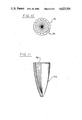
- FIG. 3 shows a side elevational view, partially in section, of a finished radome in accordance with the invention
- FIGS. 4A and 4B are cross-sectional views illustrating the step of forming a layer of composite material around a mandrel in practicing the method of FIG. 2;
- FIG. 5 is a cross-sectional view of a mandrel and composite material layer in position within an elastic bag for compacting by an isostatic pressing technique
- FIG. 6 is a side elevational view, partially in section, of a finished radome with a supporting liner bonded therein;
- FIG. 7 is a cross-sectional view of a mandrel with a helically shaped surface groove
- FIG. 8 is a side elevational view, partially in section, of a finished radome having grooves provided in both its exterior and interior surfaces;
- FIG. 9 is a cross-sectional view of the radome shown in FIG. 8 take along line 9--9;
- FIG. 10 is an end view of another mandrel for use in the practice of the present invention.
- FIG. 11 is a side elevation view, partly in section, of a finished radome produced using the mandrel of FIG. 10.
- the present invention consists of a novel unitary structures comprised of fiber-reinforced plastic material and methods of manufacture thereof. It is to be noted that while a radome and the manufacture thereof will be discussed and illustrated, the invention is not limited to such use.
- the first step in the practice of the present invention involves packing a mixture comprising reinforcing fibers and a polymeric material, preferrably polytetrafluoroethylene (hereinafter PTFE), to form a layer 12 around mandrel 10.
- PTFE polytetrafluoroethylene
- the layer 12 has been shown as a double broken line to indicate that the fiber reinforced plastic is initially in the form of a powder which is subsequently compacted to reduce its thickness and increase its density.
- Mandrel 10 is preferably comprised of aluminum and has a surface contour 16 which corresponds to the desired contour of the interior surface of the radome.
- Mandrel 10 is prepared by any conventional machining technique and may be reused for processing numerous radomes of the desired shape.
- mandrel 10 is provided with undercut 14. The function of undercut 14 will be discussed below.
- Layer 12 is a thoroughly blended mixture of PTFE in powder form and reinforcing fiber. This blended mixture is prepared by a dry process which provides an intimate blending of the PTFE particles with the individual fibers. Also, the PTFE powder is sifted through a screen before blending to insure against lumps.
- Two examples of composite materials, i.e., thoroughly blended polymeric material-fiber mixtures, capable of use in the practice of the present invention are "RT/duroid" types 5650M and 5870M available from Rogers Corporation, Rogers, Conn. and comprising by weight:
- the final compounded powder i.e., the PTFE-fiber mixture, has a preferred bulk density of about 0.25 grams/cubic centimeter.
- the reinforcing fibers useful in the practice of the present invention may be comprised of a ceramic material, glass microfibers or other similar material.
- the fibers, which are inorganic, will typically range in diameter from 0.05 to 10 micrometers and will preferably have an aspect ratio of at least 30.
- the final fiber content of the mixture should range between 5% and 40% by weight.
- the PTFE-fiber composite is prepared as an aqueous slurry. If the aqueous slurry process is employed a PTFE dispersion is added along with a flocculating agent to a mixture of water and fiber. This slurry is then dewatered, by vacuum, against a mesh fabric covered form, preferably a perforated sheel shaped similarly to the mandrel 10. The resulting low density "pulp form” shape has, after drying, an inside diameter resembling the form.
- a PTFE dispersion useful in the practice of the present invention is "Fluon" AD704, produced by ICI, America.
- a mold 28 is provided with a cavity 30 that is larger than the exterior contour of the radome to be formed.
- the cavity configuration is designed to allow for the bulk factor of the mixture so as to insure that the layer 12, in its final configuration is sufficiently oversized to permit machining the outer contour by cutting away a minimal amount of trim.
- An elastic bag 32 having approximately the same shape as cavity 30, is positioned within cavity 30. The open end of bag 32 is stretched over the mold 28 and sealed against the exterior surface thereof. The space between the bag 32 and the cavity 30 is evacuated by a high volume pump (not shown) which is connected to cavity 30 through passages provided in mold 28 (also not shown). This conforms bag 32 to the surface of cavity 30.
- Mold 28 is positioned upon a base plate 34.
- Three posts 38 extend upwardly from plate 34.
- Posts 38 are arranged triangularly and are provided with threaded ends 40.
- a Y-shaped support plate 42 is supported on posts 38 by passing threaded ends 40 of the posts through apertures 44 in plate 42. Plate 42 is secured at a desired height by nuts 46 as shown.
- a mandrel support shaft comprising a pair of interconnected rods 48 and 50 extends from Y-shaped support plate 42.
- Rod 48 is provided with external threads at both ends while rod 50 is provided with only one externally threaded end.
- the second end of rod 50 has an internally threaded blind hole which engages a first end of rod 48.
- the other end of rod 48 passes through an aperture 54 in plate 42 and is held to plate 42 by a pair of nuts 52.
- Mandrel 10 engages mandrel 10.
- Mandrel 10 is lowered into cavity 30 of mold 28 until the desired spacing between the wall of cavity 30 and mandrel 10 is achieved. This spacing should be sufficient to allow the appropriate amount of PTFE composite powder 36 to be delivered into bag 32.
- An elastomeric plug 56 preferably in two sections, is positioned around the mandrel support shaft. Plug 56 is provided with a hole 58 which, while allowing passage of rods 48 and 50, provides a tight enough fit to seal a vacuum. Plug 56 is also provided with a cavity 62, which receives a self-sealing rubber stopper 64, and an evacuation port 66 which extends from the bottom of cavity 62.
- the PTFE composite powder 36 is seived into the space between mandrel 10 and bag 32. Caution must be taken while loading the powder 36 to insure even distribution of the powder 36 within bag 32 and light tamping and/or vibration may be employed.
- bag 32 is closed. This is accomplished by sliding elastomeric disc plug 56 down shafts 48 and 50 until it contacts mandrel 10.
- the bag 32 is then taped to the plug 56, preferably by plastic pressure-sensitive tape 60, as shown in FIG. 4B. This prevents liquid intrusion into bag 32 during isostatic pressing step 20.
- a fabric strip 68 is positioned between the two sections of plug 56 in the vacinity of port 66 before bag 32 is sealed to the plug.
- the fabric strip defines a gas flow path between the sections of the plug and functions as a filter which prevents the evacuation of powder.
- a large bore hypodermic needle 70 is then pierced through stopper 64 into port 66. The air is drawn out of bag 32 and powder 36 by attaching needle 70 to a vacuum pump (not shown) through tubing 72. This evacuation step will typically consist of pumping down the sealed and powder filled bag for at least one hour.
- isostatic pressing step 20 is commenced. This involves removing the mandrel 10 with bag 32 and composite powder layer 36 from mold 28 as a unit and placing this unitary assembly in a cold isostatic press which consists of a high pressure vessel (not shown) filled with water or other suitable liquid that will not degrade bags 32 and 78.
- the pressure of the liquid is raised slowly to the maximum desired value, preferably 30,000 psi, over a time span of about an hour. The maximum pressure is held for about 5 minutes. The pressure is then slowly reduced at a constant rate to 14.7 psi over a time span of 45 to 60 minutes.
- the controlled release of pressure is typically achieved by a high pressure needle value. Caution must be taken not to release the pressure too rapidly. If the pressure is released too rapidly, the compacted powder layer may fracture. While the above are the preferred pressures and times for the isostatic pressing of a PTFE composite layer, the maximum pressure may range from 5000 psi to 100,000 psi and be reached within 30 to 60 minutes. The maximum pressure should be held between 1 to 10 minutes. Furthermore, it is also possible to reduce the pressure from the maximum to atmospheric pressure within 5 to 60 minutes. As noted above, mandrel 10 is provided with undercut 14. This insures that layer 12 of compacted PTFE composite is locked and retained upon mandrel 10 after the completion of pressing step 20.
- the powder After completion of isostatic pressing step 20 the powder has been compacted into a layer 12 (FIGS. 1 and 6) which is very nearly at the ultimate desired density and which has a major percentage of fibers oriented as desired.
- the fibers in layer 12, before the isostatic pressing step 20, are randomly oriented substantially equally in all directions.
- the pressure applied during step 20 is in a direction normal to the surface of mandrel 10. This causes a large percentage of the fibers within the powder being compacted to become randomly oriented in planes which are perpendicular to lines (not shown) which are normal to the nearest surface of mandrel 10. This may be contrasted to the technique of U.S. Pat. No. 4,364,884 wherein the principal fiber orientation is in planes which are perpendicular to the radome axis.
- the mandrel 10 and compressed layer 12 are subjected to a sintering step 22.
- a sintering step 22 This involves removing the mandrel 10 and layer 12 from the elastomeric bag 32 and subjecting layer 12 to a temperature ranging between 350° C. to 400° C., with the preferred temperature being 380° C.
- This heating is carried out by placing the mandrel 10 with layer 12 in a forced circulation oven (not shown) which is provided with an inert atmosphere, preferably nitrogen.
- the sintering temperature is reached within 3 to 30 hours and held between 1 to 8 hours.
- the mandrel and layer 12 are then cooled to room temperature.
- Caution must be taken during cooling and heating the mandrel 10 and layer 12 to insure that a significant temperature differential is not established across the layer 12. This is especially critical as the temperature passes through the crystalline melting temperature of the PTFE and also as the temperature is lowered through the recrystallization temperature of the PTFE. If the temperature difference between the mandrel 10 and the exterior surface of the PTFE composite layer becomes too great the radome may crack. While sintering with layer 12 still positioned upon mandrel 10 is the preferred procedure, it is also possible to remove layer 12 from mandrel 10 prior to sintering step 22. This is accomplished by either machining the layer 12 to remove the locking tabs which engage undercut 14 or employing a mandrel which does not have the undercut. The sintering temperature and times remain the same for both methods.
- layer 12 is finished by machining it to the desired dimensions of the radome. If layer 12 remains upon mandrel 10 during sintering step 22, the mandrel 10 may be used as a support fixture for the concentric finishing of the outside contour of layer 12.
- the completed radome is obtained by removing layer 12 from mandrel 10. This is accomplished, as noted above, by a machining operation to separate the material around undercut 14.
- an added advantage of retaining layer 12 upon mandrel 10 during sintering step 22 is that the final percentage of fibers having the desired orientation is improved. This is a result of layer 12 being locked to undercut 14. Normally, layer 12 would creep up as it shrinks during the heating. By heating locked to undercut 14, layer 12 must stretch as it shrinks in order to accommodate mandrel 10. This causes further compression of layer 12 in a direction normal to the axis (not shown) of mandrel 10.
- radome 26 which is comprised of a compacted and sintered layer 12 of PTFE composite, may be produced in any desired shape by using an appropriately designed mandrel 10.
- microwave reflection may be reduced. This reduction of reflection broadens the useable frequency range for the particular radome. It is believed that this reduction in reflection is a result of a gradual transition from the dielectric constant of the air to the dielectric constant of the radome material which results from the uniformly uneven surface contour.
- a radome 26 is shown with internal grooves 84 and external grooves 86.
- the internal grooves 84 are formed by molding the blended powder of PTFE and fibers around a mandrel 10 (FIG. 7) which is provided with a circumferentially oriented groove 88 in the form of a spiral or helix. In this manner the radome 26 can be removed from the mandrel 10 after it is sintered by twisting. The result is a radome 26 which has an inwardly spiraling groove 84, as seen best in FIG. 9, on its inner surface.
- the exterior surface of radome 26 is provided with longitudinal grooves 86 during the final machining step 24.
- the grooves 86 are longitudinal and radiate outwardly from the tip 90 of radome 26, but any configuration is possible.
- FIG. 10 shows a mandrel 92 which is provided with longitudinal grooves 94 which forms longitudinal grooves 96 in the interior surface of radome 26 of FIG. 11.
- the fiber orientation will be tangent to the average of the nearest mandrel surface.
- the grooves 96 there will be regions wherein the majority of the fibers will not lie in planes which are perpendicular to lines normal to the mandrel surface.
Landscapes
- Engineering & Computer Science (AREA)
- Mechanical Engineering (AREA)
- Chemical & Material Sciences (AREA)
- Composite Materials (AREA)
Abstract
Description
______________________________________
"RT/duroid" type       5650 M   5870 M
"Teflon" 7A (polytetrafluoroethylene,
                       75%      85%
available from E. I. duPont)
Ceramic fibers         25%       0%
(aluminum silicate fibers of random
size and having an average diameter
of about 1 μm and an average length
exceeding 100 μm)
Glass Microfibers      0        15%
(available from the John-Manville Corp.
and having an average diameter of
about 0.2 μm and an length
exceeding 30 μm)
______________________________________
Claims (19)
Priority Applications (1)
| Application Number | Priority Date | Filing Date | Title |
|---|---|---|---|
| US06/342,057 US4623505A (en) | 1981-05-13 | 1982-01-25 | Method of improving structures comprised of fiber reinforced plastic |
Applications Claiming Priority (2)
| Application Number | Priority Date | Filing Date | Title |
|---|---|---|---|
| US06/263,191 US4615859A (en) | 1981-05-13 | 1981-05-13 | Method of manufacture of improved radome structure |
| US06/342,057 US4623505A (en) | 1981-05-13 | 1982-01-25 | Method of improving structures comprised of fiber reinforced plastic |
Related Parent Applications (1)
| Application Number | Title | Priority Date | Filing Date |
|---|---|---|---|
| US06/263,191 Continuation-In-Part US4615859A (en) | 1981-05-13 | 1981-05-13 | Method of manufacture of improved radome structure |
Related Child Applications (1)
| Application Number | Title | Priority Date | Filing Date |
|---|---|---|---|
| US06/762,694 Division US4656069A (en) | 1981-05-13 | 1985-08-05 | Structures comprised of fiber reinforced plastic |
Publications (1)
| Publication Number | Publication Date |
|---|---|
| US4623505A true US4623505A (en) | 1986-11-18 |
Family
ID=26949699
Family Applications (1)
| Application Number | Title | Priority Date | Filing Date |
|---|---|---|---|
| US06/342,057 Expired - Fee Related US4623505A (en) | 1981-05-13 | 1982-01-25 | Method of improving structures comprised of fiber reinforced plastic |
Country Status (1)
| Country | Link |
|---|---|
| US (1) | US4623505A (en) |
Cited By (5)
| Publication number | Priority date | Publication date | Assignee | Title |
|---|---|---|---|---|
| US4879081A (en) * | 1988-07-15 | 1989-11-07 | Eastman Kodak Company | Process of making fused, oriented-grain polymeric materials |
| US5269982A (en) * | 1992-02-12 | 1993-12-14 | Brotz Gregory R | Process for manufacturing a shaped product |
| US5429782A (en) * | 1992-12-15 | 1995-07-04 | Nitto Denko Corporation | Process for producing polytetrafluoroethylene molded article |
| US5599489A (en) * | 1993-01-18 | 1997-02-04 | Onoda Cement Co., Ltd. | Preparing molded articles of fluorine-containing polymer with increased water-repellency |
| US20040195735A1 (en) * | 2003-04-02 | 2004-10-07 | Latvaitis J. Dean | Mandrel for forming inert anodes |
Citations (14)
| Publication number | Priority date | Publication date | Assignee | Title |
|---|---|---|---|---|
| US2937401A (en) * | 1956-04-04 | 1960-05-24 | Pastushin Aviat Corp | Method of and apparatus for molding and curing plastic material |
| US3235637A (en) * | 1964-03-09 | 1966-02-15 | Haveg Industries Inc | Process for molding polymers of halohydrocarbons |
| US3235636A (en) * | 1963-04-11 | 1966-02-15 | Hercules Powder Co Ltd | Method of molding teflon |
| US3336873A (en) * | 1965-06-28 | 1967-08-22 | Paul B Wilford | Radome nose for a missile, and method of making same |
| US3383444A (en) * | 1965-09-15 | 1968-05-14 | Navy Usa | Method of constructing radome |
| US3470284A (en) * | 1965-05-14 | 1969-09-30 | Gundlach Gmbh Aug | Device for producing refractory bodies and a method of producing such bodies |
| US3523148A (en) * | 1968-01-04 | 1970-08-04 | Battelle Development Corp | Isostatic pressure transmitting apparatus and method |
| US3897527A (en) * | 1969-11-03 | 1975-07-29 | Lars Ringdal | Method of manufacturing articles from hot solid filler material coated with thermoplastic material |
| US3962393A (en) * | 1974-05-07 | 1976-06-08 | Lockheed Aircraft Corporation | Method for making a hollow laminated article |
| US4102969A (en) * | 1975-04-10 | 1978-07-25 | Institut Textile De France | Method for manufacturing crimped textile elements by fibrillation of films |
| US4285896A (en) * | 1977-06-06 | 1981-08-25 | The Dow Chemical Company | Isostatic molding process and seal |
| US4342679A (en) * | 1980-08-27 | 1982-08-03 | Millipore Corporation | Wear-resistant sintered composition having an empirical formula CF1.3 comprising graphite fibers, fluonnated graphite, and PTFE |
| US4364884A (en) * | 1980-05-15 | 1982-12-21 | Rogers Corporation | Method of manufacturing a radome |
| US4451833A (en) * | 1980-05-15 | 1984-05-29 | Rogers Corporation | Radome formed of segmented rings of fiber-PTFE composite |
-
1982
- 1982-01-25 US US06/342,057 patent/US4623505A/en not_active Expired - Fee Related
Patent Citations (14)
| Publication number | Priority date | Publication date | Assignee | Title |
|---|---|---|---|---|
| US2937401A (en) * | 1956-04-04 | 1960-05-24 | Pastushin Aviat Corp | Method of and apparatus for molding and curing plastic material |
| US3235636A (en) * | 1963-04-11 | 1966-02-15 | Hercules Powder Co Ltd | Method of molding teflon |
| US3235637A (en) * | 1964-03-09 | 1966-02-15 | Haveg Industries Inc | Process for molding polymers of halohydrocarbons |
| US3470284A (en) * | 1965-05-14 | 1969-09-30 | Gundlach Gmbh Aug | Device for producing refractory bodies and a method of producing such bodies |
| US3336873A (en) * | 1965-06-28 | 1967-08-22 | Paul B Wilford | Radome nose for a missile, and method of making same |
| US3383444A (en) * | 1965-09-15 | 1968-05-14 | Navy Usa | Method of constructing radome |
| US3523148A (en) * | 1968-01-04 | 1970-08-04 | Battelle Development Corp | Isostatic pressure transmitting apparatus and method |
| US3897527A (en) * | 1969-11-03 | 1975-07-29 | Lars Ringdal | Method of manufacturing articles from hot solid filler material coated with thermoplastic material |
| US3962393A (en) * | 1974-05-07 | 1976-06-08 | Lockheed Aircraft Corporation | Method for making a hollow laminated article |
| US4102969A (en) * | 1975-04-10 | 1978-07-25 | Institut Textile De France | Method for manufacturing crimped textile elements by fibrillation of films |
| US4285896A (en) * | 1977-06-06 | 1981-08-25 | The Dow Chemical Company | Isostatic molding process and seal |
| US4364884A (en) * | 1980-05-15 | 1982-12-21 | Rogers Corporation | Method of manufacturing a radome |
| US4451833A (en) * | 1980-05-15 | 1984-05-29 | Rogers Corporation | Radome formed of segmented rings of fiber-PTFE composite |
| US4342679A (en) * | 1980-08-27 | 1982-08-03 | Millipore Corporation | Wear-resistant sintered composition having an empirical formula CF1.3 comprising graphite fibers, fluonnated graphite, and PTFE |
Cited By (6)
| Publication number | Priority date | Publication date | Assignee | Title |
|---|---|---|---|---|
| US4879081A (en) * | 1988-07-15 | 1989-11-07 | Eastman Kodak Company | Process of making fused, oriented-grain polymeric materials |
| US5269982A (en) * | 1992-02-12 | 1993-12-14 | Brotz Gregory R | Process for manufacturing a shaped product |
| US5429782A (en) * | 1992-12-15 | 1995-07-04 | Nitto Denko Corporation | Process for producing polytetrafluoroethylene molded article |
| US5599489A (en) * | 1993-01-18 | 1997-02-04 | Onoda Cement Co., Ltd. | Preparing molded articles of fluorine-containing polymer with increased water-repellency |
| US20040195735A1 (en) * | 2003-04-02 | 2004-10-07 | Latvaitis J. Dean | Mandrel for forming inert anodes |
| US7323134B2 (en) * | 2003-04-02 | 2008-01-29 | Alcoa, Inc. | Method of forming inert anodes |
Similar Documents
| Publication | Publication Date | Title |
|---|---|---|
| US4615859A (en) | Method of manufacture of improved radome structure | |
| US4659598A (en) | Radome structure | |
| US5921754A (en) | Composite turbine rotor | |
| US2728698A (en) | Cementable polytetrafluoroethylene and the method of making articles thereof cementable | |
| US4615933A (en) | Radome structure and method of manufacture thereof | |
| US5770127A (en) | Carbon or graphite foam reinforced composites | |
| US3718720A (en) | Method for manufacturing fibrous, carbonaceous composites having near isotropic properties | |
| US4364884A (en) | Method of manufacturing a radome | |
| US4707314A (en) | Process for producing polytetrafluoroethylene porous films | |
| US20090309268A1 (en) | Method for producing structures of complex shapes of composite materials | |
| US4623505A (en) | Method of improving structures comprised of fiber reinforced plastic | |
| US4579703A (en) | Method of manufacturing articles of ceramic material | |
| JP5217219B2 (en) | Polytetrafluoroethylene fine powder molding method, preform and molded product | |
| US4656069A (en) | Structures comprised of fiber reinforced plastic | |
| JPS6354237A (en) | Porous ptfe | |
| Manocha et al. | Development of carbon foam from phenolic resin via template route | |
| US4531273A (en) | Method for fabricating graphite filled sintered metal seats for ball valves | |
| US4451833A (en) | Radome formed of segmented rings of fiber-PTFE composite | |
| USH1332H (en) | Thermal conductive material | |
| US4949921A (en) | Method of molding fiber reinforced glass matrix composite articles | |
| US3716610A (en) | Method of making improved nose caps for missiles and rockets | |
| US4927345A (en) | Press cylinder for high-temperature, high-pressure pressing machine | |
| US4126653A (en) | Method of manufacturing silicon nitride products | |
| US3320058A (en) | Method of producing a porous tungsten structure with an impervious skin | |
| WO2002058917A2 (en) | Use of a liquid during centrifugal processing to improve consolidation of a composite structure |
Legal Events
| Date | Code | Title | Description |
|---|---|---|---|
| AS | Assignment |
Owner name: ROGERS CORPORATION, ROGERS, CT. A CORP. OF MASS. Free format text: ASSIGNMENT OF ASSIGNORS INTEREST.;ASSIGNOR:TRAUT, G. ROBERT;REEL/FRAME:003963/0358 Effective date: 19820113 |
|
| FEPP | Fee payment procedure |
Free format text: PAYOR NUMBER ASSIGNED (ORIGINAL EVENT CODE: ASPN); ENTITY STATUS OF PATENT OWNER: LARGE ENTITY |
|
| FPAY | Fee payment |
Year of fee payment: 4 |
|
| FEPP | Fee payment procedure |
Free format text: PAYER NUMBER DE-ASSIGNED (ORIGINAL EVENT CODE: RMPN); ENTITY STATUS OF PATENT OWNER: LARGE ENTITY Free format text: PAYOR NUMBER ASSIGNED (ORIGINAL EVENT CODE: ASPN); ENTITY STATUS OF PATENT OWNER: LARGE ENTITY |
|
| AS | Assignment |
Owner name: NORTON PERFORMANCE PLASTICS CORPORATION, NEW JERSE Free format text: ASSIGNMENT OF ASSIGNORS INTEREST;ASSIGNOR:ROGERS CORPORATION;REEL/FRAME:006831/0139 Effective date: 19940107 |
|
| FPAY | Fee payment |
Year of fee payment: 8 |
|
| REMI | Maintenance fee reminder mailed | ||
| LAPS | Lapse for failure to pay maintenance fees | ||
| FP | Lapsed due to failure to pay maintenance fee |
Effective date: 19981118 |
|
| STCH | Information on status: patent discontinuation |
Free format text: PATENT EXPIRED DUE TO NONPAYMENT OF MAINTENANCE FEES UNDER 37 CFR 1.362 |