US4623267A - Elastomeric bearing system - Google Patents
Elastomeric bearing system Download PDFInfo
- Publication number
- US4623267A US4623267A US06/571,621 US57162184A US4623267A US 4623267 A US4623267 A US 4623267A US 57162184 A US57162184 A US 57162184A US 4623267 A US4623267 A US 4623267A
- Authority
- US
- United States
- Prior art keywords
- mass
- tension
- supplying member
- bores
- biasing means
- Prior art date
- Legal status (The legal status is an assumption and is not a legal conclusion. Google has not performed a legal analysis and makes no representation as to the accuracy of the status listed.)
- Expired - Lifetime
Links
- 229920001971 elastomer Polymers 0.000 claims abstract description 44
- 239000000806 elastomer Substances 0.000 claims abstract description 34
- 229920002379 silicone rubber Polymers 0.000 claims abstract description 18
- 239000004945 silicone rubber Substances 0.000 claims abstract description 18
- 238000005299 abrasion Methods 0.000 claims abstract description 10
- 238000005336 cracking Methods 0.000 claims abstract description 9
- 239000005060 rubber Substances 0.000 claims description 10
- 230000000149 penetrating effect Effects 0.000 claims description 3
- 239000013536 elastomeric material Substances 0.000 claims 3
- 230000006835 compression Effects 0.000 claims 1
- 238000007906 compression Methods 0.000 claims 1
- 239000000463 material Substances 0.000 description 9
- 239000002184 metal Substances 0.000 description 4
- 229920001296 polysiloxane Polymers 0.000 description 4
- 229920003052 natural elastomer Polymers 0.000 description 3
- 229920001194 natural rubber Polymers 0.000 description 3
- 244000043261 Hevea brasiliensis Species 0.000 description 2
- 239000010687 lubricating oil Substances 0.000 description 2
- 230000000694 effects Effects 0.000 description 1
- 238000001125 extrusion Methods 0.000 description 1
- 238000010070 extrusion (rubber) Methods 0.000 description 1
- 238000005297 material degradation process Methods 0.000 description 1
- 230000013011 mating Effects 0.000 description 1
- 238000000034 method Methods 0.000 description 1
- 238000003801 milling Methods 0.000 description 1
- 238000012986 modification Methods 0.000 description 1
- 230000004048 modification Effects 0.000 description 1
- 238000000465 moulding Methods 0.000 description 1
- 238000010068 moulding (rubber) Methods 0.000 description 1
- 239000003921 oil Substances 0.000 description 1
- 239000004033 plastic Substances 0.000 description 1
- 238000003825 pressing Methods 0.000 description 1
- 230000000717 retained effect Effects 0.000 description 1
- 230000035939 shock Effects 0.000 description 1
- 229920003051 synthetic elastomer Polymers 0.000 description 1
- 239000005061 synthetic rubber Substances 0.000 description 1
Images

Classifications
-
- A—HUMAN NECESSITIES
- A63—SPORTS; GAMES; AMUSEMENTS
- A63B—APPARATUS FOR PHYSICAL TRAINING, GYMNASTICS, SWIMMING, CLIMBING, OR FENCING; BALL GAMES; TRAINING EQUIPMENT
- A63B21/00—Exercising apparatus for developing or strengthening the muscles or joints of the body by working against a counterforce, with or without measuring devices
- A63B21/02—Exercising apparatus for developing or strengthening the muscles or joints of the body by working against a counterforce, with or without measuring devices using resilient force-resisters
- A63B21/055—Exercising apparatus for developing or strengthening the muscles or joints of the body by working against a counterforce, with or without measuring devices using resilient force-resisters extension element type
-
- A—HUMAN NECESSITIES
- A63—SPORTS; GAMES; AMUSEMENTS
- A63B—APPARATUS FOR PHYSICAL TRAINING, GYMNASTICS, SWIMMING, CLIMBING, OR FENCING; BALL GAMES; TRAINING EQUIPMENT
- A63B71/00—Games or sports accessories not covered in groups A63B1/00 - A63B69/00
- A63B71/02—Games or sports accessories not covered in groups A63B1/00 - A63B69/00 for large-room or outdoor sporting games
- A63B71/023—Supports, e.g. poles
- A63B2071/026—Supports, e.g. poles stabilised by weight
- A63B2071/027—Supports, e.g. poles stabilised by weight using player's own weight, e.g. on a platform
-
- A—HUMAN NECESSITIES
- A63—SPORTS; GAMES; AMUSEMENTS
- A63B—APPARATUS FOR PHYSICAL TRAINING, GYMNASTICS, SWIMMING, CLIMBING, OR FENCING; BALL GAMES; TRAINING EQUIPMENT
- A63B21/00—Exercising apparatus for developing or strengthening the muscles or joints of the body by working against a counterforce, with or without measuring devices
- A63B21/00058—Mechanical means for varying the resistance
- A63B21/00061—Replaceable resistance units of different strengths, e.g. for swapping
-
- A—HUMAN NECESSITIES
- A63—SPORTS; GAMES; AMUSEMENTS
- A63B—APPARATUS FOR PHYSICAL TRAINING, GYMNASTICS, SWIMMING, CLIMBING, OR FENCING; BALL GAMES; TRAINING EQUIPMENT
- A63B21/00—Exercising apparatus for developing or strengthening the muscles or joints of the body by working against a counterforce, with or without measuring devices
- A63B21/00058—Mechanical means for varying the resistance
- A63B21/00065—Mechanical means for varying the resistance by increasing or reducing the number of resistance units
-
- A—HUMAN NECESSITIES
- A63—SPORTS; GAMES; AMUSEMENTS
- A63B—APPARATUS FOR PHYSICAL TRAINING, GYMNASTICS, SWIMMING, CLIMBING, OR FENCING; BALL GAMES; TRAINING EQUIPMENT
- A63B21/00—Exercising apparatus for developing or strengthening the muscles or joints of the body by working against a counterforce, with or without measuring devices
- A63B21/02—Exercising apparatus for developing or strengthening the muscles or joints of the body by working against a counterforce, with or without measuring devices using resilient force-resisters
- A63B21/04—Exercising apparatus for developing or strengthening the muscles or joints of the body by working against a counterforce, with or without measuring devices using resilient force-resisters attached to static foundation, e.g. a user
- A63B21/0407—Anchored at two end points, e.g. installed within an apparatus
- A63B21/0421—Anchored at two end points, e.g. installed within an apparatus the ends moving relatively by a pivoting arrangement
Definitions
- This invention relates to a bearing system for protection of an elastomer mass adapted to be stressed by a force supplying member formed of a material which is harder than the elastomer.
- Lubricating oil will temporarily reduce the coefficient of friction and relieve the lines of extreme stress by spreading the compressive forces over a larger area, but most oils will either attack the surface of the rubber or will be squeezed out and expelled from the interface by the action of compressing the elastomer. The use of lubricating oils is also unacceptable commercially in many applications.
- the invention embraces an elastomeric bearing system for support of an elastomer mass stressed by a force supplying member which is relatively hard compared to the elastomer, comprising the elastomeric mass having a surface subject to stress by the force supplying member, and a layer of silicone rubber positioned substantially against such surface and interposed between the elastomer mass and force supplying member, the silicone rubber layer serving as a bearing to distribute stresses and protect the elastomer mass from abrasion and cracking.
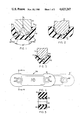
- FIG. 1 is a partial sectional view illustrating the resultant abrasion and stress cracking which normally occurs when an elastomer mass is repeatedly stressed by a metal force supplying member, illustrating the problem which the present invention solves;
- FIG. 2 is a sectional view showing the bearing system of the invention which ameliorates the unacceptable condition shown in FIG. 1;
- FIG. 3 shows a variation of the bearing system of FIG. 2
- FIG. 4 is a side view of a molded tension strap formed in accordance with the invention, and also shown in the stressed position (in phantom);
- FIG. 5 is an elevational sectional view of the bearing system taken along section 5--5 of FIG. 4;
- FIG. 6 is a perspective view of an exercise apparatus utilizing the tension straps of FIG. 4;
- FIG. 7 is a partial perspective rearward view of the tension strap connection shown in FIG. 6;
- FIG. 8 is a partial elevational sectional view of an alternative embodiment of the invention.
- elastomer mass 10 is compressed against force supplying member 12 formed of a material harder than the elastomer mass, such as metal or hard plastic.
- the elastomer mass 10 which may, for instance, be formed of natural or synthetic rubber is provided with a curvilinear bearing surface 14, which may be semi-circular as shown.
- the portions of the elastomer mass adjacent bearing surface 14 may also be restrained or placed in tension by respective forces F 2 and F 3 .
- a bearing member 11 formed of silicone rubber is interposed between elastomer mass 10 and force supplying member 12.
- Silicone rubber bearing 11 is preferably of a substantially uniform thickness "t" preferably exceeding about 0.080 inches.
- This relatively thin layer of silicone rubber interposed between the hard material of the force supplying member, particularly metal, and the relatively soft elastomer e.g., rubber material of mass 10 is believed to reduce the relative coefficient of friction between the materials with the silicone rubber layer providing lubricity.
- the silicone rubber layer acts a bearing in that it relieves and spreads the forces that would otherwise tend to destroy the elastomer mass 10 as previously discussed in respect to FIG. 1. Many different materials were tested for layer 11, however only silicone rubber was found to be effective.
- the elastomer mass 10 and silicone rubber layer 11 be free from permanent mutual attachment such as by bonding. This allows for relative movement between the parts when stressed by the force supplying member, and aids in distributing the forces and preventing the stress concentrations which result otherwise in the abrasion and stress cracking shown in FIG. 1.
- the elastomer mass 10 have a curvilinear bearing surface 14, which may be preformed by molding, extrusion, milling or the like, as shown in FIG. 3 the bearing surface 14' (shown in the stressed condition) may, in the unloaded condition be non-curvilinear as shown in phantom at 24.
- the bearing system of the invention will have various applications which will be appreciated by those of ordinary skill in the art.
- the bearing system of the invention is applicable to rubber motor mounts which are continually flexed in use.
- the silicone layer would be interposed between the engine and the rubber mount and/or between the mount and frame where it is attached.
- tension biasing means in an exercise or other device, such as the exercise apparatus shown in U.S. Pat. No. 4,072,309 to Wilson.
- tension biasing means Such a device is represented in FIGS. 6 and 7 and includes a T-shaped base frame 26 from which a vertical rail 28 extends upwardly. Rail 28 has flange 30 carrying a series of vertically oriented bores 32 for pivotally attaching an exercise lever arm 34, and a bench 36, both adjustably attached to the rail 30.
- lever arm 34 is pivotally connected to rail 30 through integral (e.g., welded) side fingers 34a and 34b which straddle the vertical support 28 and are joined thereto by pin 36 which links fingers 34a and 34b through a selected bore 32.
- integral (e.g., welded) side fingers 34a and 34b which straddle the vertical support 28 and are joined thereto by pin 36 which links fingers 34a and 34b through a selected bore 32.
- Two pairs of tension straps 38 of the invention link lever arm 34 with upright rail 28 and provide a resistive or biasing force when an exerciser attempts to press the handle 35 of the lever arm in a direction tending to elongate the rubber tension strap 38 i.e., upwardly in the arrangement of FIGS. 6 and 7.
- the tension straps 38 have spaced bores 40, as shown in FIG. 4, which are slidably mounted respectively on pin 42, attached to fingers 34a and 34b, and pin 44 penetrating a selected bore 32 in flange 30 of the upright rail.
- the tension strap of the invention is formed of an elongated elastomer mass 41, molded of a high elasticity elastomer such as natural rubber, in which silicone, rubber bearings 43 of spool shape are mounted adjacent bores 40.
- the silicone rubber bearings 43 have been separately molded and inserted subsequently into the bores 40, without bonding or covulcanizing the bearing and molded rubber strap 41 together.
- the strap is stretched to a position such as shown in phantom of FIG. 4 with portions of rubber mass 41' being compressed and other portions being placed in tension. Portions of rubber mass 41' may have sliding movement relative to silicone bearing 43' at the mutual interface therebetween.
- the apparent lubricity afforded by the silicone bearing allows a virtually unimpeded movement between the parts along the mutual interface, particularly between points A and B and between points C and D where stresses and abrasion would be at a maximum in the elastomer mass but for the presence of the interposed silicone rubber layer.
- the spool design shown in FIG. 5 is preferred since the flange portions 45 register with and are retained by mating molded recesses in elastomer mass 41, as shown in FIG. 5.
- the straps 38 may carry an imprinted designation thereon to signify the effective resistive force rating of the strap at full extension.
- the resistive force can obviously be varied by material selection e.g., modulus change, by changing the material thickness, by the number of straps used, and the like.
- FIG. 8 An alternative is shown in FIG. 8 in which the tension straps 38', three of which are shown adjacently attached to pin 44, are joined thereto through an interposed sleeve of silicone rubber extrusion or molding 47.
- sleeve 47 may first be installed over pin 44 and the desired number of tension straps 38' which have a straight bore therein without any other bearing, are mounted directly over the sleeved pin.
- the tension straps 38 of the invention have been tested according to a dynamic test in which lever arm 34 of the apparatus of FIG. 6 is repeatedly raised and lowered whereby the strap 38 is elongated from a no load center distance of about 6 inches between bores 40, to a center distance of about 111/2 inches.
- the tension strap of FIG. 4 of the invention with bearing 43 having a minimum wall thickness of 0.095 inches, an average of 50,000 to 70,000 cycles are obtained before a stress crack of 9/16 inch is induced in the elastomer mass.
Abstract
Description
Claims (2)
Priority Applications (2)
| Application Number | Priority Date | Filing Date | Title |
|---|---|---|---|
| US06/571,621 US4623267A (en) | 1984-01-17 | 1984-01-17 | Elastomeric bearing system |
| US06/868,818 US4749286A (en) | 1984-01-17 | 1986-05-29 | Elastomeric bearing system |
Applications Claiming Priority (1)
| Application Number | Priority Date | Filing Date | Title |
|---|---|---|---|
| US06/571,621 US4623267A (en) | 1984-01-17 | 1984-01-17 | Elastomeric bearing system |
Related Child Applications (1)
| Application Number | Title | Priority Date | Filing Date |
|---|---|---|---|
| US06/868,818 Division US4749286A (en) | 1984-01-17 | 1986-05-29 | Elastomeric bearing system |
Publications (1)
| Publication Number | Publication Date |
|---|---|
| US4623267A true US4623267A (en) | 1986-11-18 |
Family
ID=24284436
Family Applications (1)
| Application Number | Title | Priority Date | Filing Date |
|---|---|---|---|
| US06/571,621 Expired - Lifetime US4623267A (en) | 1984-01-17 | 1984-01-17 | Elastomeric bearing system |
Country Status (1)
| Country | Link |
|---|---|
| US (1) | US4623267A (en) |
Cited By (2)
| Publication number | Priority date | Publication date | Assignee | Title |
|---|---|---|---|---|
| US5486150A (en) * | 1993-04-30 | 1996-01-23 | Randolph; Lucian | Exercise system, apparatus and method |
| US20060255643A1 (en) * | 2005-04-15 | 2006-11-16 | Gibson John H | Combination chair and leg extension apparatus for obesity prophylaxis |
Citations (4)
| Publication number | Priority date | Publication date | Assignee | Title |
|---|---|---|---|---|
| US3193335A (en) * | 1960-09-30 | 1965-07-06 | Gen Motors Corp | Bearing |
| US4072309A (en) * | 1976-06-21 | 1978-02-07 | Wilson Jerry Lee | Multi-purpose exercise device |
| US4401198A (en) * | 1981-03-30 | 1983-08-30 | Kunczynski Jan K | Friction-based, motion damping assembly for a chairlift or the like |
| US4473308A (en) * | 1983-08-22 | 1984-09-25 | The B. F. Goodrich Company | Bearing assembly |
-
1984
- 1984-01-17 US US06/571,621 patent/US4623267A/en not_active Expired - Lifetime
Patent Citations (5)
| Publication number | Priority date | Publication date | Assignee | Title |
|---|---|---|---|---|
| US3193335A (en) * | 1960-09-30 | 1965-07-06 | Gen Motors Corp | Bearing |
| US4072309A (en) * | 1976-06-21 | 1978-02-07 | Wilson Jerry Lee | Multi-purpose exercise device |
| US4072309B1 (en) * | 1976-06-21 | 1984-03-06 | ||
| US4401198A (en) * | 1981-03-30 | 1983-08-30 | Kunczynski Jan K | Friction-based, motion damping assembly for a chairlift or the like |
| US4473308A (en) * | 1983-08-22 | 1984-09-25 | The B. F. Goodrich Company | Bearing assembly |
Cited By (3)
| Publication number | Priority date | Publication date | Assignee | Title |
|---|---|---|---|---|
| US5486150A (en) * | 1993-04-30 | 1996-01-23 | Randolph; Lucian | Exercise system, apparatus and method |
| US20060255643A1 (en) * | 2005-04-15 | 2006-11-16 | Gibson John H | Combination chair and leg extension apparatus for obesity prophylaxis |
| US7445586B2 (en) | 2005-04-15 | 2008-11-04 | John Gibson | Combination chair and leg extension apparatus for obesity prophylaxis |
Similar Documents
| Publication | Publication Date | Title |
|---|---|---|
| US4749286A (en) | Elastomeric bearing system | |
| CA1208245A (en) | Axile clamp for filament reinforced synthetic material leaf springs | |
| US5980430A (en) | Tread board for treaders | |
| EP1201964A3 (en) | Tensioner with relief valve mechanism | |
| EP0464888A1 (en) | A gasket with soft and hard seal coatings | |
| EP0714613A3 (en) | Article of footwear having multiple fluid containing members | |
| EP0837264A3 (en) | Mechanical chain tensioner with belleville springs | |
| EP1157925A3 (en) | Snubber thrust mount | |
| US2927830A (en) | Piston seal | |
| EP0965467A2 (en) | Leaf spring suspension system | |
| US3754474A (en) | Gripper pad | |
| GB2223823A (en) | An impact absorbing support member | |
| US4623267A (en) | Elastomeric bearing system | |
| US20020069539A1 (en) | Blade tensioner | |
| CA1271214A (en) | Elastomeric bearing system | |
| CA2414875C (en) | Conveyor belt cleaner blade | |
| Brown et al. | Interplay between intermolecular interactions and chain pullout in the adhesion of elastomer | |
| US4123120A (en) | Noise reducing device in undercarriage of track-type vehicle | |
| CA2151629A1 (en) | Adjustable Elastomer Torsion Device | |
| GB2045343A (en) | Hinge point | |
| CA1058099A (en) | Friction material land configuration | |
| US2126837A (en) | Elastic wall member | |
| EP0922878A3 (en) | Torsional vibration damper | |
| CN2135081Y (en) | Plate spring | |
| EP0099196A1 (en) | Composite springs |
Legal Events
| Date | Code | Title | Description |
|---|---|---|---|
| AS | Assignment |
Owner name: GATES RUBBER COMPANY THE 999 S BROADWAY DENVER CO Free format text: ASSIGNMENT OF ASSIGNORS INTEREST.;ASSIGNOR:WHITE, LARRY F.;REEL/FRAME:004224/0668 Effective date: 19840117 |
|
| STCF | Information on status: patent grant |
Free format text: PATENTED CASE |
|
| FPAY | Fee payment |
Year of fee payment: 4 |
|
| AS | Assignment |
Owner name: HELLER FINANCIAL, INC., ILLINOIS Free format text: SECURITY INTEREST;ASSIGNOR:LONGWOOD ELASTOMERS, INC., A VIRGINIA CORPORATION;REEL/FRAME:006696/0779 Effective date: 19930827 |
|
| AS | Assignment |
Owner name: LONGWOOD ELASTOMERS, INC., NEW JERSEY Free format text: ASSIGNMENT OF ASSIGNORS INTEREST;ASSIGNOR:GATES RUBBER COMPANY, THE A COLORADO CORPORATION;REEL/FRAME:006713/0941 Effective date: 19930827 |
|
| FEPP | Fee payment procedure |
Free format text: PAYOR NUMBER ASSIGNED (ORIGINAL EVENT CODE: ASPN); ENTITY STATUS OF PATENT OWNER: LARGE ENTITY |
|
| REMI | Maintenance fee reminder mailed | ||
| FPAY | Fee payment |
Year of fee payment: 8 |
|
| SULP | Surcharge for late payment | ||
| FPAY | Fee payment |
Year of fee payment: 12 |
|
| SULP | Surcharge for late payment | ||
| AS | Assignment |
Owner name: GENERAL ELECTRIC CAPITAL CORPORATION, AS AGENT, IL Free format text: AMENDED & RESTATED PATENT, TRADEMARK AND COPYRIGHT SECURITY AGREEMENT;ASSIGNORS:LONGWOOD INDUSTRIES, INC.;LONGWOOD ELASTOMERS, INC.;FAIRPRENE INC.;AND OTHERS;REEL/FRAME:014981/0911 Effective date: 20040126 |