US461663A - Grinding-machine - Google Patents
Grinding-machine Download PDFInfo
- Publication number
- US461663A US461663A US461663DA US461663A US 461663 A US461663 A US 461663A US 461663D A US461663D A US 461663DA US 461663 A US461663 A US 461663A
- Authority
- US
- United States
- Prior art keywords
- grinding
- frame
- wheels
- shafts
- driving
- Prior art date
- Legal status (The legal status is an assumption and is not a legal conclusion. Google has not performed a legal analysis and makes no representation as to the accuracy of the status listed.)
- Expired - Lifetime
Links
- 238000010586 diagram Methods 0.000 description 2
- 229910001651 emery Inorganic materials 0.000 description 2
- 239000000463 material Substances 0.000 description 2
- 238000000034 method Methods 0.000 description 2
- GVGLGOZIDCSQPN-PVHGPHFFSA-N Heroin Chemical compound O([C@H]1[C@H](C=C[C@H]23)OC(C)=O)C4=C5[C@@]12CCN(C)[C@@H]3CC5=CC=C4OC(C)=O GVGLGOZIDCSQPN-PVHGPHFFSA-N 0.000 description 1
- 238000010276 construction Methods 0.000 description 1
- 229910052593 corundum Inorganic materials 0.000 description 1
- 239000010431 corundum Substances 0.000 description 1
- 238000009877 rendering Methods 0.000 description 1
- 230000000284 resting effect Effects 0.000 description 1
Images

Classifications
-
- B—PERFORMING OPERATIONS; TRANSPORTING
- B24—GRINDING; POLISHING
- B24B—MACHINES, DEVICES, OR PROCESSES FOR GRINDING OR POLISHING; DRESSING OR CONDITIONING OF ABRADING SURFACES; FEEDING OF GRINDING, POLISHING, OR LAPPING AGENTS
- B24B3/00—Sharpening cutting edges, e.g. of tools; Accessories therefor, e.g. for holding the tools
- B24B3/36—Sharpening cutting edges, e.g. of tools; Accessories therefor, e.g. for holding the tools of cutting blades
- B24B3/54—Sharpening cutting edges, e.g. of tools; Accessories therefor, e.g. for holding the tools of cutting blades of hand or table knives
Definitions
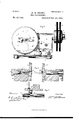
- FIG. 1 represents a plan View of a grinding-machine embodying my invention.
- Fig. 2 is a sectional view on line X X, Fig. 1.
- Fig. 3 represents a central sectional view of a portion of the two driving-shafts having coincident axes, showing the method by which rotary motion is conveyed from one of said driving-shafts to the other.
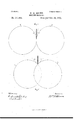
- FIG. 4 is a sectional view of a portion of the base and supporting framework on line Y Y, Fig. 1, showing the method of adjust'ably attaching the movable portion of the frame upon the base; and Figs.'5 and 6 are diagrams illustrating the variation in the angle between the peripheries of the grinding-wheels as produced by changing the distance between the centers of the grinding-wheels.
- My invention relates to a machine for grinding knives, scissors, and similar cutting-tools; and itconsists in the construction and arran gement of the several parts, as hereinafter described, and set forth in the claims.
- A denotes the base adapted to be attached by screws or clamps to any supporting stand or table, and upon which is mounted the frame-work B B, upon which are mounted the operating parts of the grinding-machine.
- the portion B of the frame-work is rigidly attached to the base A, and in the fixed portion B is journaled a driving-shaft O, carrying a crank C, by which it is rotated, and a driving-gear O engaging a pinion C upon a spindle O journaled in a bearing upon the frame B and carrying the grinding-wheels D D, separated slightly more than the thickness of the wheels by a washer D and held in place by the washer D and nut D
- the base A is provided with a V-shaped groove E near its front edge, in which is placed the cylindrical rod E, and the under side of the frames B B are provided with similar V-shaped grooves, that in the frame B being shown at E, Fig. 2. 'Theframe B is placed in position upon the base.
- the frame B is capable of being moved upon the base A, so as to vary the distance between the frames B and B, and is adj ustably attached to the base A by means of the tightening-screw I, passing through the frame 1 B and through the slot I and entering a nut I beneath the base A.
- the frame B carries an adjustin -screw J the rotation of the adjusting-screw J.
- frame B also carries a rod K, upon which a wooden roll K turns loosely, and is held in a central position between the frames B B by the tension of the springs K K the rod K having a sliding motion through the frame B.
- the driving-shafts G and F have coincident axes, andthe rotary motion of the shaft 0 is imparted to the shaft F by means of the rectangular blade L, provided with a head L, entering aconcentrie chamberin the shaft 0, the rotation of the shaft 0 being imparted to the blade L by means of a slotted plate L pivoted at L to the driving-gear C and having its opposite end held against the drivinggear C by means of the clamping-plate L attached to the gear C
- the blade L passes through a rectangular slot in the plate L, attached to the drivinggear F, and enters a concentric chamber extending nearly the entire length of the shaft F, as represented in sectional view in Fig. 3.
- the position of the frame B is adjusted with reference to the frame B in order to bring the grinding-wheels closer together, in order to compensate for wear, and also to vary the angle inclosedbetween the peripheries of the wheels for the purpose of varying the bevel upon the tool to be ground.
- the diagrams in Figs. 5 and 6 illustrate the variation in the bevel produced upon the tool to be ground by the variation of the distance between the centers of the wheels.
- the lines 1 1 represent the tangents of two opposite wheels at their greatest distance apart and inclosing between them a small angle, rendering the edge of the cutting-tool correspondingly thin
- the lines 2 2 represent tangents of the opposing wheels at the points of intersection when the wheels are moved together, the angle between the lines 2 2 being much greater than the angle inclosed between the lines 1 1 and producing a corresponding chan ge in the edge of the cutting-tool.
- the cutting-wheels are arranged in suitable relative position to produce the desired ,angle upon the edge of the cuttingtool.
- the cutting-tool is then laid across the grinding-wheels with its edge downward and placed in the angle inclosed between the pcripheries of the grinding-wheels, and as the grindingwheels are revolved by the rotation of the crank G a traversing movement is imparted to the cutting-tool backward and forward across the edge of the cutting-tool.
- a grindingmachine the combination of opposing grinding-Wheels carried upon parallel spindles, driving-shafts operatively connected with said spindles, and a blade held concentrically in said driving-shafts and 0a pable of sliding in one of said shafts, whereby the rotary motion of one of said drivingshafts is communicated to the other of said shafts at varying distances apart, substantially as described.
- a grinding-machine In a grinding-machine, the combination of a base supporting fixed and movable frames, a fixed frame carrying a rotating spindle, a grinding-wheel carried on said spindle, a movable frame adjustably attached to said base, a rotating spindle carried by said frame, a grinding-wheel carried on said spindle, driving-shafts journaled in said fixed and movable frames and operatively connected with said grinding-Wheel, spindles, and intermediate mechanism, substantially as described, whereby the motion of one of the driving-shafts is communicated to the other, substantially as described.
- a grinding-machine the combination, with a pair of spindles carrying pinions and grinding-wheels, of driving-shafts having 00- incidentaXes and carrying gear-wheels engaging the pinions on said spindles, a rectangular blade with its ends entering concentric chambers in said driving-shafts, plates attached to said gears and having rectangular openings to receive said blade, substantially as described.
Landscapes
- Engineering & Computer Science (AREA)
- Mechanical Engineering (AREA)
- Finish Polishing, Edge Sharpening, And Grinding By Specific Grinding Devices (AREA)
Description
t e e h S m e e h s 3 M 0 R B H W a d o M o W GRINDING MACHINE.
Patented Oct. 20
8141: auto z WW (No Model.)
' 3 SheetsSh,eet 2. W. H. BROWN.
GRINDING MAGHINE. N 0. 461,663.
Patented Oct. 20, 1891.
I A l E g H M QWitmc-aaao (No ModeL) 3 Sheets-Sheet 3.
W. H BROWN. GRINDING MACHINE. No. 461,663. Patergfced 0013.20, 1891.
"IIIIIII'IIIIIIIIIIIIIIIIIIJ wi/f/yvwaeo 54412014101 THE Nonms vn'zns cm, wowumm, wAsmnnToN, n. c.
NITED' STATES PATENT OFFICE.
VILLIAM H. BROWVN, OF XVOROESTER, MASSACHUSETTS.
-GRlNDlNG-MACH|NE.
SPECIFICATION forming part of Letters Patent No. 461,663, dated October 20, 1891.
Application filed May 13, 1891. Serial ITO/392,558. (No model.)
To all whom it may concern.-
Be it known that 1, WILLIAM H. BROWN, a citizen of the United States, residing at Vorcester, in the county of lVorcester and State of Massachusetts, have invented a new and useful Improvement in Grinding Machines, of which the following is a specification, reference being had to the accompanying drawings, representing a grinding-machine embodying my invention, in which Figure 1 represents a plan View of a grinding-machine embodying my invention. Fig. 2 is a sectional view on line X X, Fig. 1. Fig. 3 represents a central sectional view of a portion of the two driving-shafts having coincident axes, showing the method by which rotary motion is conveyed from one of said driving-shafts to the other. Fig. 4 is a sectional view of a portion of the base and supporting framework on line Y Y, Fig. 1, showing the method of adjust'ably attaching the movable portion of the frame upon the base; and Figs.'5 and 6 are diagrams illustrating the variation in the angle between the peripheries of the grinding-wheels as produced by changing the distance between the centers of the grinding-wheels.
Similar letters refer to similar parts in the several figures.
My invention relates to a machine for grinding knives, scissors, and similar cutting-tools; and itconsists in the construction and arran gement of the several parts, as hereinafter described, and set forth in the claims.
Referring to the drawings, A denotes the base adapted to be attached by screws or clamps to any supporting stand or table, and upon which is mounted the frame-work B B, upon which are mounted the operating parts of the grinding-machine.
The portion B of the frame-work is rigidly attached to the base A, and in the fixed portion B is journaled a driving-shaft O, carrying a crank C, by which it is rotated, and a driving-gear O engaging a pinion C upon a spindle O journaled in a bearing upon the frame B and carrying the grinding-wheels D D, separated slightly more than the thickness of the wheels by a washer D and held in place by the washer D and nut D The base A is provided with a V-shaped groove E near its front edge, in which is placed the cylindrical rod E, and the under side of the frames B B are provided with similar V-shaped grooves, that in the frame B being shown at E, Fig. 2. 'Theframe B is placed in position upon the base. A, with its V-shaped groove E resting upon the rod E and with'the rear portion of the frame supported upon the base by the leg An attaching-screw E passing through the frame B and entering a screw-threaded hole in the base A, holds the frame B firmly upon the base and upon the cylindrical rod E, which, being held in the V-shaped groove E restrains the frame B from rotating about the attaching-screw E J ournaled in the frame B is a shaft F, carrying the driving-gear E, which engages the pinion F attached to a spindle F journaled in a bearing upon the frame B and carrying the grinding-wheels G G, separated slightly more than the thickness of the wheels by the washer G and held in place by the washers G G and a nut G The grinding-wheels, of emery or similar material, are held upon their respective spindles in different planes,
so as to allow their edges to interlock, as at.
The frame B is capable of being moved upon the base A, so as to vary the distance between the frames B and B, and is adj ustably attached to the base A by means of the tightening-screw I, passing through the frame 1 B and through the slot I and entering a nut I beneath the base A.
The frame B carries an adjustin -screw J the rotation of the adjusting-screw J. The
frame B also carries a rod K, upon which a wooden roll K turns loosely, and is held in a central position between the frames B B by the tension of the springs K K the rod K having a sliding motion through the frame B.
The driving-shafts G and F have coincident axes, andthe rotary motion of the shaft 0 is imparted to the shaft F by means of the rectangular blade L, provided with a head L, entering aconcentrie chamberin the shaft 0, the rotation of the shaft 0 being imparted to the blade L by means of a slotted plate L pivoted at L to the driving-gear C and having its opposite end held against the drivinggear C by means of the clamping-plate L attached to the gear C The blade L passes through a rectangular slot in the plate L, attached to the drivinggear F, and enters a concentric chamber extending nearly the entire length of the shaft F, as represented in sectional view in Fig. 3. IVhen the frames B B are removed their extreme distance apart, the rectangular blade L just enters the rectangular slot in the plate L, and as the frame B is moved toward the frame B the end of the rectangular blade L enters the chamber L The plate L is pivoted at L to the gear G in order to permit a lateral swinging motion to the plate to allow for any variation in the alignment of the shaft C and F. The grinding-wheels D D and G G can be made of any suitable material, such as emery, corundum, &c., and they are mounted upon their respective shafts in different planes in order to allow the edges of the wheels to move by each other and in terloek as the frame B is moved toward the frame B.
The position of the frame B is adjusted with reference to the frame B in order to bring the grinding-wheels closer together, in order to compensate for wear, and also to vary the angle inclosedbetween the peripheries of the wheels for the purpose of varying the bevel upon the tool to be ground. The diagrams in Figs. 5 and 6 illustrate the variation in the bevel produced upon the tool to be ground by the variation of the distance between the centers of the wheels.
In Fig. 5 the lines 1 1 represent the tangents of two opposite wheels at their greatest distance apart and inclosing between them a small angle, rendering the edge of the cutting-tool correspondingly thin, and in Fig. 6, the lines 2 2 represent tangents of the opposing wheels at the points of intersection when the wheels are moved together, the angle between the lines 2 2 being much greater than the angle inclosed between the lines 1 1 and producing a corresponding chan ge in the edge of the cutting-tool.
In operation the cutting-wheels are arranged in suitable relative position to produce the desired ,angle upon the edge of the cuttingtool. The cutting-tool is then laid across the grinding-wheels with its edge downward and placed in the angle inclosed between the pcripheries of the grinding-wheels, and as the grindingwheels are revolved by the rotation of the crank G a traversing movement is imparted to the cutting-tool backward and forward across the edge of the cutting-tool. The
wooden roll K is held centrally between the spindles G and F by the spiral springs K and it prevents the edge of the cutting-tool from being lowered and brought in contact with the rectangular blade L.
That I claim as my invention, and desire to secure by Letters Patent, is
1. 111 a grinding-machine, the combination of the driving-shafts having coincident axes, spindles operatively connected with said driving-shafts and carrying grinding-wheels, and intermediate connecting mechanism, substantially as described, whereby the rotary motion of one of said driving-shafts is imparted to the other, substantially as described.
2. In a grindingmachine, the combination of opposing grinding-Wheels carried upon parallel spindles, driving-shafts operatively connected with said spindles, and a blade held concentrically in said driving-shafts and 0a pable of sliding in one of said shafts, whereby the rotary motion of one of said drivingshafts is communicated to the other of said shafts at varying distances apart, substantially as described.
In a grinding-machine, the combination of a base supporting fixed and movable frames, a fixed frame carrying a rotating spindle, a grinding-wheel carried on said spindle, a movable frame adjustably attached to said base, a rotating spindle carried by said frame, a grinding-wheel carried on said spindle, driving-shafts journaled in said fixed and movable frames and operatively connected with said grinding-Wheel, spindles, and intermediate mechanism, substantially as described, whereby the motion of one of the driving-shafts is communicated to the other, substantially as described.
4. In a grinding-machine, the combination, with a pair of spindles carrying pinions and grinding-wheels, of driving-shafts having 00- incidentaXes and carrying gear-wheels engaging the pinions on said spindles, a rectangular blade with its ends entering concentric chambers in said driving-shafts, plates attached to said gears and having rectangular openings to receive said blade, substantially as described.
5. In a grinding-machine, the combination, with spindles carrying grinding-wheels, of driving-shafts having coincident axes and operatively connected with said spindles, a blade held concentrically in said shafts, by which the motion of one shaft is imparted. to the other, and a pivoted plate carried by one of said shafts and provided with an opening to receive said blade, substantially as described.
6. In a grinding-machine, the combination, with grinding-wheels having connected operating mechanism, of a spindle held in the frame-work and carrying a guard-roll to hold the tool while being ground out of contact with the operating mechanism, substantially as described.
7. In a grinding-machine, the combination,
with grinding-wheels capable of adjustment B, said fixed and movable frames having relatively to each other, of a spindle K, aroll grooves E and a rod E, inelosed by said K, held on said spindle, and springs K K grooves, substantially as described.
by which said roll is held centrally on said \VM. I-I. BROWVN. 5 spindle, substantially as described. WVitnesses:
8. The-combination of a base A, having a RUFUS B. FOWLER,
groove E, a fixed frame B, a movable frame H. M. FOWLER.
Publications (1)
| Publication Number | Publication Date |
|---|---|
| US461663A true US461663A (en) | 1891-10-20 |
Family
ID=2530535
Family Applications (1)
| Application Number | Title | Priority Date | Filing Date |
|---|---|---|---|
| US461663D Expired - Lifetime US461663A (en) | Grinding-machine |
Country Status (1)
| Country | Link |
|---|---|
| US (1) | US461663A (en) |
Cited By (2)
| Publication number | Priority date | Publication date | Assignee | Title |
|---|---|---|---|---|
| US2432534A (en) * | 1944-10-25 | 1947-12-16 | Lewis M Mcbride | Knife sharpener |
| US12409526B1 (en) * | 2024-12-30 | 2025-09-09 | Hangzhou Weikai e-commerce Co., Ltd. | Electric knife sharpener |
-
0
- US US461663D patent/US461663A/en not_active Expired - Lifetime
Cited By (2)
| Publication number | Priority date | Publication date | Assignee | Title |
|---|---|---|---|---|
| US2432534A (en) * | 1944-10-25 | 1947-12-16 | Lewis M Mcbride | Knife sharpener |
| US12409526B1 (en) * | 2024-12-30 | 2025-09-09 | Hangzhou Weikai e-commerce Co., Ltd. | Electric knife sharpener |
Similar Documents
| Publication | Publication Date | Title |
|---|---|---|
| US461663A (en) | Grinding-machine | |
| US946635A (en) | Machine for grinding straight machine-knives. | |
| US108822A (en) | Improvement in machines for grinding and polishing metal | |
| US1182362A (en) | Grinding-machine. | |
| US1231920A (en) | Tool-holder for grinding-machines. | |
| US441570A (en) | Lens-grinding machine | |
| US432144A (en) | Half to merwin mckaig | |
| US222539A (en) | Improvement in grin ding-machines | |
| US626858A (en) | Leather-splitting machine | |
| US1309264A (en) | Machine foe | |
| US1155532A (en) | Trimming mechanism for grinder-wheels of shaft-grinding machines. | |
| US737313A (en) | Lens-grinding machine. | |
| US825454A (en) | Glass-grinding machine. | |
| US794159A (en) | Grinding-machine. | |
| US344359A (en) | donnelly | |
| US429698A (en) | Island | |
| US737391A (en) | Glass-beveling machine. | |
| US350351A (en) | Grinding-machine | |
| US1076801A (en) | Machine for sharpening cutting instruments. | |
| US297565A (en) | machine foe grinding cutter knives | |
| US623742A (en) | Grinding or polishing machine | |
| US741537A (en) | Knife-grinding machine. | |
| US332003A (en) | Geoege eichaeds | |
| US43005A (en) | Improved machine for grinding file-blanks | |
| US750531A (en) | Bis peteaj co |