US461461A - whitesidb - Google Patents
whitesidb Download PDFInfo
- Publication number
- US461461A US461461A US461461DA US461461A US 461461 A US461461 A US 461461A US 461461D A US461461D A US 461461DA US 461461 A US461461 A US 461461A
- Authority
- US
- United States
- Prior art keywords
- disk
- wheel
- lever
- machine
- coin
- Prior art date
- Legal status (The legal status is an assumption and is not a legal conclusion. Google has not performed a legal analysis and makes no representation as to the accuracy of the status listed.)
- Expired - Lifetime
Links
- 230000033001 locomotion Effects 0.000 description 3
- 238000010276 construction Methods 0.000 description 2
- 241000557626 Corvus corax Species 0.000 description 1
- 210000003323 beak Anatomy 0.000 description 1
- 150000001768 cations Chemical class 0.000 description 1
- 235000019219 chocolate Nutrition 0.000 description 1
Images


Classifications
-
- G—PHYSICS
- G07—CHECKING-DEVICES
- G07F—COIN-FREED OR LIKE APPARATUS
- G07F17/00—Coin-freed apparatus for hiring articles; Coin-freed facilities or services
- G07F17/04—Coin-freed apparatus for hiring articles; Coin-freed facilities or services for anthropometrical measurements, such as weight, height, strength
- G07F17/045—Coin-freed apparatus for hiring articles; Coin-freed facilities or services for anthropometrical measurements, such as weight, height, strength for weighing persons
Definitions
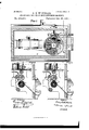
- Figure 1 represents a side view of my improved machine, the wall of the casing being removed to display the interior mechanism.
- Fig. 2 is a top view of two disks that are used in said mechanism, the said figure showing them displaced from the relative position they occupy in the machine.
- Fig. 3 is a plan or top view of the mechanism of the machine, the casing being shown in horizontal section.
- Figs. 4 and 5 are vertical cross-sections on the line 0 c
- Fig. 6 is a vertical section on the line 1.: 75
- Fig. '7 is a detail side view of part of the mechanism used in the machine; and
- Fig. 8 is a detail section on the line k is, Fig. 7.
- This invention relates to anew machine for distributing coins, packages, or the like on the introduction of other coins, and may be used in connection with a stamp-delivery apparatus of the kind substantially described in my application, Serial No. 332,686, for a patent for mailing-machines, which was filed December 5, 1889, but may also be used independently of such stampdistributing mechanism.
- the letter A represents the outer casing of my improved machine, which is box-like in form, as usual, and which at any proper part has an opening at (see Fig. 7) for introducing a coin B, the object of which coin in my machine is to move a lever C on its pivot b.
- the drawings, Fig. 7, shows the" coin B when introduced to 45 separate two locking-levers 61 (Z from engagement with two vibrating fingers e e, which fingers, when they close together behind the introduced coin B under influence of their springs ff, propel the coin B against the le- 50 ver 0; but as I do not here claim any part of the mechanism df I likewise do not confine Serial No. 379,371. (No model.) 7
- the lever O is hook-shaped, its beak g being adapted to engage over a pin h, that projects from a wheel.
- a spring 2' bears against the lever 0, so as to hold it in either of its two positionsthat is, either in engagement with the pin h,
- the lever O is also provided with a projecting arm j, which is so located that it will be in the path of the pin h when the'same is revolved with the wheel D.
- the wheel D is by preference connected with a ratchetwheel, as shown, a pawl Z entering its teeth'to simply prevent backward movement of said wheel, the forward movement being indicated by the arrow 1 in Fig. 7.
- the drawings represent a handle m to be afliXed to the arbor n of the wheel D, so that by turning said handle the wheel D may revolve around its axis in the direction of the arrow 1 as soon as the lever O liberates the pin h under the influence of an introduced coin.
- a pinion 0 which gears into a toothed wheel 19, which in turn engages with a toothed disk- E, all arranged so that one rotation of the wheel D will produce, say, one-quarter revolution of the disk 5 E; but these proportions may of course be modified at pleasure, and it is not necessary to employ the intermediate wheel 19, since the pinion 0 may gear directly into the teeth of the disk E, or any other means well known to mechanics for imparting rotary mot-ion from the the arbor n to the disk E may be employed.
- a stationary plate F which has but an aperture 8 of the same size,'substantially as or larger than one of the holes of the'disk E, the holes in the disk E being all of equal size, or the said plate F may be cut off, as indicated by lines 0 c, Fig. 2.
- the machine is intended to sell for a five-cent piece two two-cent stamps and to return one penny as change.
- the contents of the package-receptacles G G G will be the pennies; but the invention is equally useful for the sale of other things than pennies, such as packages of chocolate or the like, in which case, of course, it is necessary that the disk E shall have a thickness equal to the height of the package to be sold.
- the disk E When the disk E receives a quarter-turn, it carries one of its apertures containing a penny or other package into alignment with the hole 3 of the stationary plate F, and permits, therefore, said penny to drop through the aperture 3 into a chute t, from which the purchaser may conveniently remove it.
- stamp-delivery device may be of the construction shown in Figs. 4 and 5, beingsubstantiallythe same construction as is more fully described in my above-mentioned application, Serial No.
- stamp-delivering mechanism would consist of a stamp-reel II, from which the paper I passes between a sleeve J on a stationary drum L and a springcarried frictionroller M, and thence over the cutting device N, again between the sleeve J and a lower feed-roller 0, all as indicated in the drawings, but more fully specified in my above application.
Landscapes
- Physics & Mathematics (AREA)
- General Physics & Mathematics (AREA)
- Vending Machines For Individual Products (AREA)
Description
(No Model.) 3 Sheets-Sheet 1.
S. B. WHITESIDE. STAMP SELLING AND CHANGE RETURNING MACHINE.
No. 461,461. Patented Oct. 20, 1891.
F 71 5- I ihlhl (No Model.) 3 Sheets-Sheet 2.
A S. B. WHITESIDE.
STAMP SELLING AND GHANGB RETURNING MACHINE.
- No. 461,461. Patented Oct. 20, 1891.
A T TOR/VIE Y3 cums ravens 1:04, van-m1 1 (N-oModel.) 3 Sheets- Sheet 3 S. B. WHITBSIDE. STAMP SELLING AND CHANGE RETURNING MACHINE.
No. 461,461. vmmnlmd Oct. 20, 1891.
llllll lllll II n nm 1' ull!"- lllll 7 lllllllllll];
' WITNESSES: INVENTOR- (Milka,
' THE new: rang qo moro-umo wAsnmuYon n c UNITED STATES PATENT OFF CE.
SIDNEY B. WHITESIDE, OF SAN FRANCISCO, CALIFORNIA, ASSIGNOR TO THE POSTAGE STAMP SERVICE MACHINE COMPANY, OF NEW YORK, N. Y.
STAMP-SELLING AND CHANGE-RETURNING MACHINE;
SPECIFICATION forming part of Letters Patent No. 461,461, dated October 20, 1891.
Application filed January 28, 1891.
To all whom it may concern.-
Be it known that l, SIDNEY B. WHITEsIDE,
a resident of San Francisco, San Francisco county, California, have invented an Improved Stamp-Selling and Change-Returning Machine, of which the following is a speciii: cation, reference being had to the accompanying drawings, forming part thereof, wherein Figure 1 represents a side view of my improved machine, the wall of the casing being removed to display the interior mechanism. Fig. 2 is a top view of two disks that are used in said mechanism, the said figure showing them displaced from the relative position they occupy in the machine. Fig. 3 is a plan or top view of the mechanism of the machine, the casing being shown in horizontal section. Figs. 4 and 5 are vertical cross-sections on the line 0 c, Fig. 3. Fig. 6 is a vertical section on the line 1.: 75, Fig. 3. Fig. '7 is a detail side view of part of the mechanism used in the machine; and Fig. 8 is a detail section on the line k is, Fig. 7.
This invention relates to anew machine for distributing coins, packages, or the like on the introduction of other coins, and may be used in connection with a stamp-delivery apparatus of the kind substantially described in my application, Serial No. 332,686, for a patent for mailing-machines, which was filed December 5, 1889, but may also be used independently of such stampdistributing mechanism.
The invention consists in the novel combinations and arrangements of parts hereinafter more fully described.
In the accompanying drawings, the letter A represents the outer casing of my improved machine, which is box-like in form, as usual, and which at any proper part has an opening at (see Fig. 7) for introducing a coin B, the object of which coin in my machine is to move a lever C on its pivot b. The drawings, Fig. 7, shows the" coin B when introduced to 45 separate two locking-levers 61 (Z from engagement with two vibrating fingers e e, which fingers, when they close together behind the introduced coin B under influence of their springs ff, propel the coin B against the le- 50 ver 0; but as I do not here claim any part of the mechanism df I likewise do not confine Serial No. 379,371. (No model.) 7
myself thereto. Any chute or other contrivance that will conduct the purchasing-coin to the lever C, so as to cause the coin to vibrate said lever on its pivot, will answer the 5 purpose of this my invention. The lever O is hook-shaped, its beak g being adapted to engage over a pin h, that projects from a wheel. D. A spring 2' bears against the lever 0, so as to hold it in either of its two positionsthat is, either in engagement with the pin h,
as in Fig. 7, or out of engagement therewith. The lever O isalso provided with a projecting arm j, which is so located that it will be in the path of the pin h when the'same is revolved with the wheel D. The wheel D is by preference connected with a ratchetwheel, as shown, a pawl Z entering its teeth'to simply prevent backward movement of said wheel, the forward movement being indicated by the arrow 1 in Fig. 7. \Vhenever a coin B is introduced into the machine so that it strikes the lever O and swings the same on its pivotb the said lever G will thereby become disengaged from the pin h, and will be held by the spring 2' in its new position, and when thus the pin it is liberated from contact with the lever C the wheel D will be free to make a' revolution around its axis in the direction of the arrow 1. This rotation may be imparted to the wheel D by hand, if desired, but may also be imparted to it by a spring properly wound or by a weight, or in other suitable manner. The drawings representa handle m to be afliXed to the arbor n of the wheel D, so that by turning said handle the wheel D may revolve around its axis in the direction of the arrow 1 as soon as the lever O liberates the pin h under the influence of an introduced coin. Upon the arbor of the 0 wheel D is also mounted a pinion 0, which gears into a toothed wheel 19, which in turn engages with a toothed disk- E, all arranged so that one rotation of the wheel D will produce, say, one-quarter revolution of the disk 5 E; but these proportions may of course be modified at pleasure, and it is not necessary to employ the intermediate wheel 19, since the pinion 0 may gear directly into the teeth of the disk E, or any other means well known to mechanics for imparting rotary mot-ion from the the arbor n to the disk E may be employed. As
the wheelD rotates the pin h comes in contact with the arm j of the lever O, and thereby swingsthelever 0 back into theposition shown 'in Fig.7, so that at the termination of one revolution the hook 9 will again arrest the. pin h. Thus but a single revolution of the wheel D is permitted asa result of the introduction of every single coin B. It follows that every revolution of the coin B permits of a quarter-revolution of the disk E. Said disk E is shown in top View, Fig. 2. Its rotation is to take place in the direction of the arrow 2 shown in Fig. 2. lhis rotary disk E is represented as having four apertures r r r W.
Directly below the disk E is a stationary plate F, which has but an aperture 8 of the same size,'substantially as or larger than one of the holes of the'disk E, the holes in the disk E being all of equal size, or the said plate F may be cut off, as indicated by lines 0 c, Fig. 2.
Above the disk E is stationarily secured a series of Vertical package receptacles or tubes G, G and G each being open at the bottom and each arranged so that when the aperture 0" is directly above the aperture 3, the tube G will stand above the aperture 0" the tube G above the aperture 7*, and the tube G above the aperture r In order that. the reader of this specification may not be misled,'I will here repeat that in the machine the diskF is directly beneath the disk E and not in the relation shown in Fig. 2, which shows the disk F pulled away quite a distance from beneath the disk E. Each of the tubes G G G is filled with pennies or other things to be sold. For the purpose of this illustration, we will assume that the machine is intended to sell for a five-cent piece two two-cent stamps and to return one penny as change. In that case, therefore, the contents of the package-receptacles G G G will be the pennies; but the invention is equally useful for the sale of other things than pennies, such as packages of chocolate or the like, in which case, of course, it is necessary that the disk E shall have a thickness equal to the height of the package to be sold.
In operation, when the disk E receives a quarter-turn, it carries one of its apertures containing a penny or other package into alignment with the hole 3 of the stationary plate F, and permits, therefore, said penny to drop through the aperture 3 into a chute t, from which the purchaser may conveniently remove it.
I have represented in the drawings three tubes G G G and three holes 7", 4*, and r to correspond thereto, and I desire it to be understood here that the three tubes are not essential. One tube will answer the purpose; but
for distributing a larger number of packages or pennies an unnecessary length of tube is economized by using a number side by side, as in the drawings. In operation one of the tubes will be emptied first before the next one will be emptied, and finally the last. Thus at first a penny from each tube lies in each of the holes r r r As one-quarter of a revolution of the disk E is made the penny in T will first be discharged; but at the same time a penny from the tube G enters the aperture 1'. At the next quarter-revolution of the disk E the penny from riwill be discharged, but at the same time a penny from G enters the aperture r At the third quarter-revolution a penny from 1" will be discharged, but at the same time the aperture 0" receives a new coin from the tube G, &c. It thus appears that the tube G will first be emptied, after which the tube G will be emptied, and finally the tube G but if instead of quarter-revolutions the disk E would make one-third of arevolution at each time, there would be but two tubes or package -receptacles G G required, and three holes equally far apart formed-in the disk E.
\Vhen, as has been said, this mechanism is to be used in connection with a stamp-delivery device, such stamp-delivery device may be of the construction shown in Figs. 4 and 5, beingsubstantiallythe same construction as is more fully described in my above-mentioned application, Serial No. 332,686; and I therefore do not deem it necessary to describe the same at great length, it sufficing to state here that such stamp-delivering mechanism would consist of a stamp-reel II, from which the paper I passes between a sleeve J on a stationary drum L and a springcarried frictionroller M, and thence over the cutting device N, again between the sleeve J and a lower feed-roller 0, all as indicated in the drawings, but more fully specified in my above application.
What I claim, and desire to secure by Letters Patent, is-
1. The combination of the lever 0, having projecting arm j and hook g, with the spring t', wheel D, and pin h on said wheel, all arranged for operation substantially as herein shown and described.
2. The combination of the lever 0, having arm j and hook g, with the spring 1', wheel D, having pin it, gearing connecting said Wheel D with the apertured disk E, package-reservoir G, and stationary perforated plate F, all
arranged substantially as herein shown and described.
SIDNEY B. IVHITESIDE.
IVitnesses:
HARRY M. TURK, HENRY E. EVERDING.
Publications (1)
| Publication Number | Publication Date |
|---|---|
| US461461A true US461461A (en) | 1891-10-20 |
Family
ID=2530333
Family Applications (1)
| Application Number | Title | Priority Date | Filing Date |
|---|---|---|---|
| US461461D Expired - Lifetime US461461A (en) | whitesidb |
Country Status (1)
| Country | Link |
|---|---|
| US (1) | US461461A (en) |
Cited By (5)
| Publication number | Priority date | Publication date | Assignee | Title |
|---|---|---|---|---|
| US2611468A (en) * | 1947-11-21 | 1952-09-23 | Rock Ola Mfg Corp | Coin chute mechanism |
| US2653850A (en) * | 1949-11-17 | 1953-09-29 | Theodore F Vollten | Combination storage and dispensing rack |
| US3018148A (en) * | 1958-07-07 | 1962-01-23 | Oak Mfg Co Inc | Dispenser |
| US3054528A (en) * | 1961-05-29 | 1962-09-18 | Evarts G Loomis | Machines for vending paper and pencils |
| US3980167A (en) * | 1974-12-30 | 1976-09-14 | Omron Tateisi Electronics Co. | Entry control device |
-
0
- US US461461D patent/US461461A/en not_active Expired - Lifetime
Cited By (5)
| Publication number | Priority date | Publication date | Assignee | Title |
|---|---|---|---|---|
| US2611468A (en) * | 1947-11-21 | 1952-09-23 | Rock Ola Mfg Corp | Coin chute mechanism |
| US2653850A (en) * | 1949-11-17 | 1953-09-29 | Theodore F Vollten | Combination storage and dispensing rack |
| US3018148A (en) * | 1958-07-07 | 1962-01-23 | Oak Mfg Co Inc | Dispenser |
| US3054528A (en) * | 1961-05-29 | 1962-09-18 | Evarts G Loomis | Machines for vending paper and pencils |
| US3980167A (en) * | 1974-12-30 | 1976-09-14 | Omron Tateisi Electronics Co. | Entry control device |
Similar Documents
| Publication | Publication Date | Title |
|---|---|---|
| US2633960A (en) | Coin-handling apparatus | |
| US1321385A (en) | Coin-controlled vending-machine | |
| US487409A (en) | Coin-actuated vending-machine | |
| US1881831A (en) | Commodity vending machine | |
| US750718A (en) | spear | |
| US2262783A (en) | Vehicle parking meter | |
| US644720A (en) | Automatic vending and indicating apparatus. | |
| US708687A (en) | Exhibiting and vending machine. | |
| US918549A (en) | Weighing and vending apparatus. | |
| US1052607A (en) | Merchandise-vending machine. | |
| US688545A (en) | Counting-machine. | |
| US1186578A (en) | Coin-controlled registering mechanism. | |
| US1043006A (en) | Coin-handling apparatus. | |
| US449164A (en) | Island | |
| US582685A (en) | Coin-controlled apparatus | |
| US741932A (en) | Toy. | |
| US555076A (en) | Electric visual indicator | |
| US712911A (en) | Coin-freed apparatus for delivering gas. | |
| USRE11479E (en) | Victor p | |
| US429927A (en) | long-acre | |
| US959063A (en) | Vending-machine. | |
| US430389A (en) | krause | |
| US552460A (en) | winkler | |
| US620690A (en) | Coin-controlled vending and display apparatus | |
| US957534A (en) | Prepayment electricity-meter. |