US4614078A - Apparatus for transversely sealing packages - Google Patents
Apparatus for transversely sealing packages Download PDFInfo
- Publication number
- US4614078A US4614078A US06/759,032 US75903285A US4614078A US 4614078 A US4614078 A US 4614078A US 75903285 A US75903285 A US 75903285A US 4614078 A US4614078 A US 4614078A
- Authority
- US
- United States
- Prior art keywords
- outer mold
- mold
- inner mold
- rotatable body
- tubular member
- Prior art date
- Legal status (The legal status is an assumption and is not a legal conclusion. Google has not performed a legal analysis and makes no representation as to the accuracy of the status listed.)
- Expired - Fee Related
Links
Images


Classifications
-
- B—PERFORMING OPERATIONS; TRANSPORTING
- B65—CONVEYING; PACKING; STORING; HANDLING THIN OR FILAMENTARY MATERIAL
- B65B—MACHINES, APPARATUS OR DEVICES FOR, OR METHODS OF, PACKAGING ARTICLES OR MATERIALS; UNPACKING
- B65B9/00—Enclosing successive articles, or quantities of material, e.g. liquids or semiliquids, in flat, folded, or tubular webs of flexible sheet material; Subdividing filled flexible tubes to form packages
- B65B9/06—Enclosing successive articles, or quantities of material, in a longitudinally-folded web, or in a web folded into a tube about the articles or quantities of material placed upon it
- B65B9/08—Enclosing successive articles, or quantities of material, in a longitudinally-folded web, or in a web folded into a tube about the articles or quantities of material placed upon it in a web folded and sealed transversely to form pockets which are subsequently filled and then closed by sealing
- B65B9/087—Enclosing successive articles, or quantities of material, in a longitudinally-folded web, or in a web folded into a tube about the articles or quantities of material placed upon it in a web folded and sealed transversely to form pockets which are subsequently filled and then closed by sealing the web advancing continuously
-
- B—PERFORMING OPERATIONS; TRANSPORTING
- B29—WORKING OF PLASTICS; WORKING OF SUBSTANCES IN A PLASTIC STATE IN GENERAL
- B29C—SHAPING OR JOINING OF PLASTICS; SHAPING OF MATERIAL IN A PLASTIC STATE, NOT OTHERWISE PROVIDED FOR; AFTER-TREATMENT OF THE SHAPED PRODUCTS, e.g. REPAIRING
- B29C65/00—Joining or sealing of preformed parts, e.g. welding of plastics materials; Apparatus therefor
- B29C65/78—Means for handling the parts to be joined, e.g. for making containers or hollow articles, e.g. means for handling sheets, plates, web-like materials, tubular articles, hollow articles or elements to be joined therewith; Means for discharging the joined articles from the joining apparatus
- B29C65/7858—Means for handling the parts to be joined, e.g. for making containers or hollow articles, e.g. means for handling sheets, plates, web-like materials, tubular articles, hollow articles or elements to be joined therewith; Means for discharging the joined articles from the joining apparatus characterised by the feeding movement of the parts to be joined
- B29C65/7879—Means for handling the parts to be joined, e.g. for making containers or hollow articles, e.g. means for handling sheets, plates, web-like materials, tubular articles, hollow articles or elements to be joined therewith; Means for discharging the joined articles from the joining apparatus characterised by the feeding movement of the parts to be joined said parts to be joined moving in a closed path, e.g. a rectangular path
- B29C65/7882—Means for handling the parts to be joined, e.g. for making containers or hollow articles, e.g. means for handling sheets, plates, web-like materials, tubular articles, hollow articles or elements to be joined therewith; Means for discharging the joined articles from the joining apparatus characterised by the feeding movement of the parts to be joined said parts to be joined moving in a closed path, e.g. a rectangular path said parts to be joined moving in a circular path
- B29C65/7885—Rotary turret joining machines, i.e. having several joining tools moving around an axis
-
- B—PERFORMING OPERATIONS; TRANSPORTING
- B29—WORKING OF PLASTICS; WORKING OF SUBSTANCES IN A PLASTIC STATE IN GENERAL
- B29C—SHAPING OR JOINING OF PLASTICS; SHAPING OF MATERIAL IN A PLASTIC STATE, NOT OTHERWISE PROVIDED FOR; AFTER-TREATMENT OF THE SHAPED PRODUCTS, e.g. REPAIRING
- B29C65/00—Joining or sealing of preformed parts, e.g. welding of plastics materials; Apparatus therefor
- B29C65/02—Joining or sealing of preformed parts, e.g. welding of plastics materials; Apparatus therefor by heating, with or without pressure
- B29C65/18—Joining or sealing of preformed parts, e.g. welding of plastics materials; Apparatus therefor by heating, with or without pressure using heated tools
-
- B—PERFORMING OPERATIONS; TRANSPORTING
- B29—WORKING OF PLASTICS; WORKING OF SUBSTANCES IN A PLASTIC STATE IN GENERAL
- B29C—SHAPING OR JOINING OF PLASTICS; SHAPING OF MATERIAL IN A PLASTIC STATE, NOT OTHERWISE PROVIDED FOR; AFTER-TREATMENT OF THE SHAPED PRODUCTS, e.g. REPAIRING
- B29C65/00—Joining or sealing of preformed parts, e.g. welding of plastics materials; Apparatus therefor
- B29C65/78—Means for handling the parts to be joined, e.g. for making containers or hollow articles, e.g. means for handling sheets, plates, web-like materials, tubular articles, hollow articles or elements to be joined therewith; Means for discharging the joined articles from the joining apparatus
- B29C65/7858—Means for handling the parts to be joined, e.g. for making containers or hollow articles, e.g. means for handling sheets, plates, web-like materials, tubular articles, hollow articles or elements to be joined therewith; Means for discharging the joined articles from the joining apparatus characterised by the feeding movement of the parts to be joined
- B29C65/7888—Means for handling of moving sheets or webs
- B29C65/7894—Means for handling of moving sheets or webs of continuously moving sheets or webs
-
- B—PERFORMING OPERATIONS; TRANSPORTING
- B29—WORKING OF PLASTICS; WORKING OF SUBSTANCES IN A PLASTIC STATE IN GENERAL
- B29C—SHAPING OR JOINING OF PLASTICS; SHAPING OF MATERIAL IN A PLASTIC STATE, NOT OTHERWISE PROVIDED FOR; AFTER-TREATMENT OF THE SHAPED PRODUCTS, e.g. REPAIRING
- B29C65/00—Joining or sealing of preformed parts, e.g. welding of plastics materials; Apparatus therefor
- B29C65/78—Means for handling the parts to be joined, e.g. for making containers or hollow articles, e.g. means for handling sheets, plates, web-like materials, tubular articles, hollow articles or elements to be joined therewith; Means for discharging the joined articles from the joining apparatus
- B29C65/7897—Means for discharging the joined articles from the joining apparatus
-
- B—PERFORMING OPERATIONS; TRANSPORTING
- B29—WORKING OF PLASTICS; WORKING OF SUBSTANCES IN A PLASTIC STATE IN GENERAL
- B29C—SHAPING OR JOINING OF PLASTICS; SHAPING OF MATERIAL IN A PLASTIC STATE, NOT OTHERWISE PROVIDED FOR; AFTER-TREATMENT OF THE SHAPED PRODUCTS, e.g. REPAIRING
- B29C66/00—General aspects of processes or apparatus for joining preformed parts
- B29C66/01—General aspects dealing with the joint area or with the area to be joined
- B29C66/05—Particular design of joint configurations
- B29C66/10—Particular design of joint configurations particular design of the joint cross-sections
- B29C66/11—Joint cross-sections comprising a single joint-segment, i.e. one of the parts to be joined comprising a single joint-segment in the joint cross-section
- B29C66/112—Single lapped joints
- B29C66/1122—Single lap to lap joints, i.e. overlap joints
-
- B—PERFORMING OPERATIONS; TRANSPORTING
- B29—WORKING OF PLASTICS; WORKING OF SUBSTANCES IN A PLASTIC STATE IN GENERAL
- B29C—SHAPING OR JOINING OF PLASTICS; SHAPING OF MATERIAL IN A PLASTIC STATE, NOT OTHERWISE PROVIDED FOR; AFTER-TREATMENT OF THE SHAPED PRODUCTS, e.g. REPAIRING
- B29C66/00—General aspects of processes or apparatus for joining preformed parts
- B29C66/40—General aspects of joining substantially flat articles, e.g. plates, sheets or web-like materials; Making flat seams in tubular or hollow articles; Joining single elements to substantially flat surfaces
- B29C66/41—Joining substantially flat articles ; Making flat seams in tubular or hollow articles
- B29C66/43—Joining a relatively small portion of the surface of said articles
- B29C66/431—Joining the articles to themselves
- B29C66/4312—Joining the articles to themselves for making flat seams in tubular or hollow articles, e.g. transversal seams
-
- B—PERFORMING OPERATIONS; TRANSPORTING
- B29—WORKING OF PLASTICS; WORKING OF SUBSTANCES IN A PLASTIC STATE IN GENERAL
- B29C—SHAPING OR JOINING OF PLASTICS; SHAPING OF MATERIAL IN A PLASTIC STATE, NOT OTHERWISE PROVIDED FOR; AFTER-TREATMENT OF THE SHAPED PRODUCTS, e.g. REPAIRING
- B29C66/00—General aspects of processes or apparatus for joining preformed parts
- B29C66/40—General aspects of joining substantially flat articles, e.g. plates, sheets or web-like materials; Making flat seams in tubular or hollow articles; Joining single elements to substantially flat surfaces
- B29C66/41—Joining substantially flat articles ; Making flat seams in tubular or hollow articles
- B29C66/43—Joining a relatively small portion of the surface of said articles
- B29C66/432—Joining a relatively small portion of the surface of said articles for making tubular articles or closed loops, e.g. by joining several sheets ; for making hollow articles or hollow preforms
- B29C66/4322—Joining a relatively small portion of the surface of said articles for making tubular articles or closed loops, e.g. by joining several sheets ; for making hollow articles or hollow preforms by joining a single sheet to itself
-
- B—PERFORMING OPERATIONS; TRANSPORTING
- B29—WORKING OF PLASTICS; WORKING OF SUBSTANCES IN A PLASTIC STATE IN GENERAL
- B29C—SHAPING OR JOINING OF PLASTICS; SHAPING OF MATERIAL IN A PLASTIC STATE, NOT OTHERWISE PROVIDED FOR; AFTER-TREATMENT OF THE SHAPED PRODUCTS, e.g. REPAIRING
- B29C66/00—General aspects of processes or apparatus for joining preformed parts
- B29C66/70—General aspects of processes or apparatus for joining preformed parts characterised by the composition, physical properties or the structure of the material of the parts to be joined; Joining with non-plastics material
- B29C66/73—General aspects of processes or apparatus for joining preformed parts characterised by the composition, physical properties or the structure of the material of the parts to be joined; Joining with non-plastics material characterised by the intensive physical properties of the material of the parts to be joined, by the optical properties of the material of the parts to be joined, by the extensive physical properties of the parts to be joined, by the state of the material of the parts to be joined or by the material of the parts to be joined being a thermoplastic or a thermoset
- B29C66/739—General aspects of processes or apparatus for joining preformed parts characterised by the composition, physical properties or the structure of the material of the parts to be joined; Joining with non-plastics material characterised by the intensive physical properties of the material of the parts to be joined, by the optical properties of the material of the parts to be joined, by the extensive physical properties of the parts to be joined, by the state of the material of the parts to be joined or by the material of the parts to be joined being a thermoplastic or a thermoset characterised by the material of the parts to be joined being a thermoplastic or a thermoset
- B29C66/7392—General aspects of processes or apparatus for joining preformed parts characterised by the composition, physical properties or the structure of the material of the parts to be joined; Joining with non-plastics material characterised by the intensive physical properties of the material of the parts to be joined, by the optical properties of the material of the parts to be joined, by the extensive physical properties of the parts to be joined, by the state of the material of the parts to be joined or by the material of the parts to be joined being a thermoplastic or a thermoset characterised by the material of the parts to be joined being a thermoplastic or a thermoset characterised by the material of at least one of the parts being a thermoplastic
- B29C66/73921—General aspects of processes or apparatus for joining preformed parts characterised by the composition, physical properties or the structure of the material of the parts to be joined; Joining with non-plastics material characterised by the intensive physical properties of the material of the parts to be joined, by the optical properties of the material of the parts to be joined, by the extensive physical properties of the parts to be joined, by the state of the material of the parts to be joined or by the material of the parts to be joined being a thermoplastic or a thermoset characterised by the material of the parts to be joined being a thermoplastic or a thermoset characterised by the material of at least one of the parts being a thermoplastic characterised by the materials of both parts being thermoplastics
-
- B—PERFORMING OPERATIONS; TRANSPORTING
- B29—WORKING OF PLASTICS; WORKING OF SUBSTANCES IN A PLASTIC STATE IN GENERAL
- B29C—SHAPING OR JOINING OF PLASTICS; SHAPING OF MATERIAL IN A PLASTIC STATE, NOT OTHERWISE PROVIDED FOR; AFTER-TREATMENT OF THE SHAPED PRODUCTS, e.g. REPAIRING
- B29C66/00—General aspects of processes or apparatus for joining preformed parts
- B29C66/80—General aspects of machine operations or constructions and parts thereof
- B29C66/81—General aspects of the pressing elements, i.e. the elements applying pressure on the parts to be joined in the area to be joined, e.g. the welding jaws or clamps
- B29C66/816—General aspects of the pressing elements, i.e. the elements applying pressure on the parts to be joined in the area to be joined, e.g. the welding jaws or clamps characterised by the mounting of the pressing elements, e.g. of the welding jaws or clamps
- B29C66/8161—General aspects of the pressing elements, i.e. the elements applying pressure on the parts to be joined in the area to be joined, e.g. the welding jaws or clamps characterised by the mounting of the pressing elements, e.g. of the welding jaws or clamps said pressing elements being supported or backed-up by springs or by resilient material
-
- B—PERFORMING OPERATIONS; TRANSPORTING
- B29—WORKING OF PLASTICS; WORKING OF SUBSTANCES IN A PLASTIC STATE IN GENERAL
- B29C—SHAPING OR JOINING OF PLASTICS; SHAPING OF MATERIAL IN A PLASTIC STATE, NOT OTHERWISE PROVIDED FOR; AFTER-TREATMENT OF THE SHAPED PRODUCTS, e.g. REPAIRING
- B29C66/00—General aspects of processes or apparatus for joining preformed parts
- B29C66/80—General aspects of machine operations or constructions and parts thereof
- B29C66/82—Pressure application arrangements, e.g. transmission or actuating mechanisms for joining tools or clamps
- B29C66/822—Transmission mechanisms
- B29C66/8221—Scissor or lever mechanisms, i.e. involving a pivot point
-
- B—PERFORMING OPERATIONS; TRANSPORTING
- B29—WORKING OF PLASTICS; WORKING OF SUBSTANCES IN A PLASTIC STATE IN GENERAL
- B29C—SHAPING OR JOINING OF PLASTICS; SHAPING OF MATERIAL IN A PLASTIC STATE, NOT OTHERWISE PROVIDED FOR; AFTER-TREATMENT OF THE SHAPED PRODUCTS, e.g. REPAIRING
- B29C66/00—General aspects of processes or apparatus for joining preformed parts
- B29C66/80—General aspects of machine operations or constructions and parts thereof
- B29C66/82—Pressure application arrangements, e.g. transmission or actuating mechanisms for joining tools or clamps
- B29C66/822—Transmission mechanisms
- B29C66/8226—Cam mechanisms; Wedges; Eccentric mechanisms
- B29C66/82263—Follower pin or roller cooperating with a groove
-
- B—PERFORMING OPERATIONS; TRANSPORTING
- B29—WORKING OF PLASTICS; WORKING OF SUBSTANCES IN A PLASTIC STATE IN GENERAL
- B29C—SHAPING OR JOINING OF PLASTICS; SHAPING OF MATERIAL IN A PLASTIC STATE, NOT OTHERWISE PROVIDED FOR; AFTER-TREATMENT OF THE SHAPED PRODUCTS, e.g. REPAIRING
- B29C66/00—General aspects of processes or apparatus for joining preformed parts
- B29C66/80—General aspects of machine operations or constructions and parts thereof
- B29C66/82—Pressure application arrangements, e.g. transmission or actuating mechanisms for joining tools or clamps
- B29C66/822—Transmission mechanisms
- B29C66/8226—Cam mechanisms; Wedges; Eccentric mechanisms
- B29C66/82265—Eccentric mechanisms
-
- B—PERFORMING OPERATIONS; TRANSPORTING
- B29—WORKING OF PLASTICS; WORKING OF SUBSTANCES IN A PLASTIC STATE IN GENERAL
- B29C—SHAPING OR JOINING OF PLASTICS; SHAPING OF MATERIAL IN A PLASTIC STATE, NOT OTHERWISE PROVIDED FOR; AFTER-TREATMENT OF THE SHAPED PRODUCTS, e.g. REPAIRING
- B29C66/00—General aspects of processes or apparatus for joining preformed parts
- B29C66/80—General aspects of machine operations or constructions and parts thereof
- B29C66/82—Pressure application arrangements, e.g. transmission or actuating mechanisms for joining tools or clamps
- B29C66/824—Actuating mechanisms
- B29C66/8246—Servomechanisms, e.g. servomotors
-
- B—PERFORMING OPERATIONS; TRANSPORTING
- B29—WORKING OF PLASTICS; WORKING OF SUBSTANCES IN A PLASTIC STATE IN GENERAL
- B29C—SHAPING OR JOINING OF PLASTICS; SHAPING OF MATERIAL IN A PLASTIC STATE, NOT OTHERWISE PROVIDED FOR; AFTER-TREATMENT OF THE SHAPED PRODUCTS, e.g. REPAIRING
- B29C66/00—General aspects of processes or apparatus for joining preformed parts
- B29C66/80—General aspects of machine operations or constructions and parts thereof
- B29C66/83—General aspects of machine operations or constructions and parts thereof characterised by the movement of the joining or pressing tools
- B29C66/832—Reciprocating joining or pressing tools
- B29C66/8324—Joining or pressing tools pivoting around one axis
-
- B—PERFORMING OPERATIONS; TRANSPORTING
- B29—WORKING OF PLASTICS; WORKING OF SUBSTANCES IN A PLASTIC STATE IN GENERAL
- B29C—SHAPING OR JOINING OF PLASTICS; SHAPING OF MATERIAL IN A PLASTIC STATE, NOT OTHERWISE PROVIDED FOR; AFTER-TREATMENT OF THE SHAPED PRODUCTS, e.g. REPAIRING
- B29C66/00—General aspects of processes or apparatus for joining preformed parts
- B29C66/80—General aspects of machine operations or constructions and parts thereof
- B29C66/83—General aspects of machine operations or constructions and parts thereof characterised by the movement of the joining or pressing tools
- B29C66/834—General aspects of machine operations or constructions and parts thereof characterised by the movement of the joining or pressing tools moving with the parts to be joined
- B29C66/8351—Jaws mounted on rollers, cylinders, drums, bands, belts or chains; Flying jaws
- B29C66/83511—Jaws mounted on rollers, cylinders, drums, bands, belts or chains; Flying jaws jaws mounted on rollers, cylinders or drums
- B29C66/83517—Jaws mounted on rollers, cylinders, drums, bands, belts or chains; Flying jaws jaws mounted on rollers, cylinders or drums said rollers, cylinders or drums being hollow
-
- B—PERFORMING OPERATIONS; TRANSPORTING
- B29—WORKING OF PLASTICS; WORKING OF SUBSTANCES IN A PLASTIC STATE IN GENERAL
- B29C—SHAPING OR JOINING OF PLASTICS; SHAPING OF MATERIAL IN A PLASTIC STATE, NOT OTHERWISE PROVIDED FOR; AFTER-TREATMENT OF THE SHAPED PRODUCTS, e.g. REPAIRING
- B29C66/00—General aspects of processes or apparatus for joining preformed parts
- B29C66/80—General aspects of machine operations or constructions and parts thereof
- B29C66/83—General aspects of machine operations or constructions and parts thereof characterised by the movement of the joining or pressing tools
- B29C66/834—General aspects of machine operations or constructions and parts thereof characterised by the movement of the joining or pressing tools moving with the parts to be joined
- B29C66/8351—Jaws mounted on rollers, cylinders, drums, bands, belts or chains; Flying jaws
- B29C66/83541—Jaws mounted on rollers, cylinders, drums, bands, belts or chains; Flying jaws flying jaws, e.g. jaws mounted on crank mechanisms or following a hand over hand movement
-
- B—PERFORMING OPERATIONS; TRANSPORTING
- B29—WORKING OF PLASTICS; WORKING OF SUBSTANCES IN A PLASTIC STATE IN GENERAL
- B29C—SHAPING OR JOINING OF PLASTICS; SHAPING OF MATERIAL IN A PLASTIC STATE, NOT OTHERWISE PROVIDED FOR; AFTER-TREATMENT OF THE SHAPED PRODUCTS, e.g. REPAIRING
- B29C66/00—General aspects of processes or apparatus for joining preformed parts
- B29C66/80—General aspects of machine operations or constructions and parts thereof
- B29C66/84—Specific machine types or machines suitable for specific applications
- B29C66/849—Packaging machines
-
- B—PERFORMING OPERATIONS; TRANSPORTING
- B29—WORKING OF PLASTICS; WORKING OF SUBSTANCES IN A PLASTIC STATE IN GENERAL
- B29C—SHAPING OR JOINING OF PLASTICS; SHAPING OF MATERIAL IN A PLASTIC STATE, NOT OTHERWISE PROVIDED FOR; AFTER-TREATMENT OF THE SHAPED PRODUCTS, e.g. REPAIRING
- B29C66/00—General aspects of processes or apparatus for joining preformed parts
- B29C66/80—General aspects of machine operations or constructions and parts thereof
- B29C66/84—Specific machine types or machines suitable for specific applications
- B29C66/851—Bag or container making machines
- B29C66/8511—Bag making machines
-
- B—PERFORMING OPERATIONS; TRANSPORTING
- B65—CONVEYING; PACKING; STORING; HANDLING THIN OR FILAMENTARY MATERIAL
- B65B—MACHINES, APPARATUS OR DEVICES FOR, OR METHODS OF, PACKAGING ARTICLES OR MATERIALS; UNPACKING
- B65B51/00—Devices for, or methods of, sealing or securing package folds or closures; Devices for gathering or twisting wrappers, or necks of bags
- B65B51/10—Applying or generating heat or pressure or combinations thereof
- B65B51/26—Devices specially adapted for producing transverse or longitudinal seams in webs or tubes
- B65B51/30—Devices, e.g. jaws, for applying pressure and heat, e.g. for subdividing filled tubes
-
- B—PERFORMING OPERATIONS; TRANSPORTING
- B65—CONVEYING; PACKING; STORING; HANDLING THIN OR FILAMENTARY MATERIAL
- B65B—MACHINES, APPARATUS OR DEVICES FOR, OR METHODS OF, PACKAGING ARTICLES OR MATERIALS; UNPACKING
- B65B9/00—Enclosing successive articles, or quantities of material, e.g. liquids or semiliquids, in flat, folded, or tubular webs of flexible sheet material; Subdividing filled flexible tubes to form packages
- B65B9/06—Enclosing successive articles, or quantities of material, in a longitudinally-folded web, or in a web folded into a tube about the articles or quantities of material placed upon it
- B65B9/08—Enclosing successive articles, or quantities of material, in a longitudinally-folded web, or in a web folded into a tube about the articles or quantities of material placed upon it in a web folded and sealed transversely to form pockets which are subsequently filled and then closed by sealing
-
- B—PERFORMING OPERATIONS; TRANSPORTING
- B65—CONVEYING; PACKING; STORING; HANDLING THIN OR FILAMENTARY MATERIAL
- B65B—MACHINES, APPARATUS OR DEVICES FOR, OR METHODS OF, PACKAGING ARTICLES OR MATERIALS; UNPACKING
- B65B9/00—Enclosing successive articles, or quantities of material, e.g. liquids or semiliquids, in flat, folded, or tubular webs of flexible sheet material; Subdividing filled flexible tubes to form packages
- B65B9/10—Enclosing successive articles, or quantities of material, in preformed tubular webs, or in webs formed into tubes around filling nozzles, e.g. extruded tubular webs
- B65B9/12—Subdividing filled tubes to form two or more packages by sealing or securing involving displacement of contents
-
- B—PERFORMING OPERATIONS; TRANSPORTING
- B29—WORKING OF PLASTICS; WORKING OF SUBSTANCES IN A PLASTIC STATE IN GENERAL
- B29C—SHAPING OR JOINING OF PLASTICS; SHAPING OF MATERIAL IN A PLASTIC STATE, NOT OTHERWISE PROVIDED FOR; AFTER-TREATMENT OF THE SHAPED PRODUCTS, e.g. REPAIRING
- B29C66/00—General aspects of processes or apparatus for joining preformed parts
- B29C66/80—General aspects of machine operations or constructions and parts thereof
- B29C66/82—Pressure application arrangements, e.g. transmission or actuating mechanisms for joining tools or clamps
- B29C66/824—Actuating mechanisms
- B29C66/8244—Actuating mechanisms magnetically driven
-
- B—PERFORMING OPERATIONS; TRANSPORTING
- B29—WORKING OF PLASTICS; WORKING OF SUBSTANCES IN A PLASTIC STATE IN GENERAL
- B29L—INDEXING SCHEME ASSOCIATED WITH SUBCLASS B29C, RELATING TO PARTICULAR ARTICLES
- B29L2031/00—Other particular articles
- B29L2031/712—Containers; Packaging elements or accessories, Packages
Definitions
- the invention relates to an apparatus for transversely sealing packages, or more particularly, to an apparatus which seals a continuous length of tubular member at intervals in a direction transverse to the length thereof and in registration with printed patterns thereon while the member is filled with beverage or the like so that successively adjacent transverse seals define enclosed packages or containers.
- Apparatus which has been used in the prior art to produce such enclosed packages can be categorized into two types.
- a length of sheet-like material to which a thermoplastic film is applied is folded upon itself, and its overlapping ends are longitudinally sealed together by a heat sealing operation to define a tubular member.
- the tubular member is sealed at a given interval in a direction transverse to the length thereof, and the member is cut on one side of each seal, thus forming a bag-shaped container which is open at its one end.
- the bag-shaped container is supported in an upright position with the opening located on the top, and a filling such as beverage is injected into the container, whereupon the opening is sealed to define an enclosed container.
- the tubular member is formed from a length of sheet-like material as mentioned, and its one end is held sandwiched in a transverse sealing device, which closes the end by applying a transverse seal therein by a heat sealing operation. Under this condition, a filling is injected into the tubular member which has an increased length. Subsequently, the tubular member is released from the transverse sealing device, and is intermittently conveyed through a given distance, whereupon it is again held sandwiched in the transverse sealing device which then applies a transverse seal, thus allowing a filling to be introduced into the space defined between adjacent transverse seals to form an enclosed container or package.
- Such process is repeated to convey the tubular member intermittently after the injection of a filling and the application of a transverse seal thereto at a given interval by means of the transverse sealing device. Subsequently, the tubular member is cut through the central portion of the transverse seals to divide it into individual enclosed containers.
- a filling such as juice is injected after a bag-shaped container is formed which is open at its one end, so that an increased number of steps and an increased length of time are required to complete enclosed containers.
- the filling is injected into the individual bag-shaped containers, there are many chances for both the containers and the filling to be exposed to the atmosphere and hence to the invasion of miscellaneous bacteria, presenting sanitary problems.
- the described sanitary problems can be overcome since the injection of the filling occurs as the tubular member is formed.
- the tubular member is intermittently conveyed, with the transverse seals being applied during the time the tubular member remains at rest, it is difficult to achieve a high speed operation.
- Another factor relates to an increased length of dwell time to result in an inefficient operation since an increased length of time is required to provide a transverse seal in a reliable manner.
- An apparatus for transversely sealing packages comprises a rotatable body adapted to be set in continuous rotating motion, a plurality of carrier means disposed along the periphery of the rotatable body and each including an inner mold located inward and an outer mold located outward as viewed radially of the rotatable body, and drive means for urging the outer mold against the inner mold and for moving the outer mold to its open position which is laterally offset in the direction of rotation from the position where it is located opposite to the inner mold.
- a tubular member containing a filling therein is supplied to the inner mold, and a transverse seal is applied to the tubular member in a direction transverse to the direction in which it is conveyed when the outer mold is urged against the inner mold to hold the tubular member sandwiched therebetween.
- An enclosed package which is defined by adjacent transverse seals is removed out of the inner mold when the outer mold is at its open position.
- the carrier means which function to hold the tubular member therein and to seal it transversely can be rotated in an integral manner with the rotatable body so as to convey the tubular member in a continuous manner.
- the carrier means is capable of holding the tubular member sandwiched therein in a continuous manner through a given angle of rotation, whereby a time period is secured which is required to provide a transverse seal in a reliable mannner. In this manner, a high speed operation is enabled, and enclosed packages can be manufactured efficiently.
- the carrier means is disposed to be displaceable in a reciprocatory manner either in the direction of rotation or in the radial direction of the rotatable body so that the displacement of the respective carrier means in either rotational or radial direction permits a spacing between adjacent carrier means to be adjusted.
- FIG. 1 is a schematic illustration of the entire apparatus which is used to manufacture a beverage filled package, including the apparatus according to the invention
- FIG. 2a is a plan view of a sheet-like material in which fold lines are impressed according to a desired configuration
- FIG. 2b is a perspective view, partly in section, of a tubular member formed
- FIG. 2c is a perspective view of a separated box member
- FIG. 2d is a perspective view of a box member immediately before its completion
- FIG. 3 is a fragmentary front view of an apparatus for transversely sealing packages according to an embodiment of the invention.
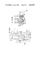
- FIG. 4 is a cross section of part of the apparatus shown in FIG. 3;
- FIG. 5 is a front view of a twisted guide groove in relation to rollers
- FIG. 6 is a fragmentary front view of a modification of the apparatus shown in FIG. 3;
- FIG. 7 is a fragmentary front view, similar to FIG. 3, of another embodiment of the invention.
- FIG. 8 is a cross section of part of the arrangement shown in FIG. 7;
- FIG. 9 is a fragmentary front view of carrier means which may be used in a further embodiment of the invention.
- FIG. 10 is a cross section of the arrangement shown in FIG. 9.
- FIG. 1 there is shown a general arrangment of an apparatus which is used to manufacture a beverage filled package.
- the general process of manufacturing packages which are filled with the beverage will be initially described with reference to FIG. 1.
- a web or continuous length of sheet-like material 1a to which a thermoplastic film is applied and which has desired patterns printed thereon is continuously supplied from a reel 2 which stores a roll thereon.
- the web supplied is passed around a plurality of guide rolls 3 to a fold line impressing unit 4 where fold lines a, required to form a package of a desired configuration, are continuously impressed in the web 1a in accordance with the printed patterns, as shown in FIG. 2a.
- the web is then passed around a plurality of guide rolls 5 to be conveyed into a folding unit 6.
- Part of the web 1a which is disposed within the folding unit 6 is folded upon itself along a fold line b (see FIG. 2a) which is impressed along the longitudinal centerline, and the folded web 1a is supplied to a following roll pair 7 while twisting it through 90°.
- the folded web 1a which is supplied to the roll pair 7 has the fold line b located on one side thereof while the opposite ends or edges of the web which were previously located on the opposite sides of the fold line b and which now overlap each other as a result of the folding operation are located on the other side.
- the folded web 1a After leaving the roll pair 7, the folded web 1a is diverted by being passed around a roll 8, and is fed vertically downward into a heater 9 which heats the web 1a and also through heat sealing press roll pairs 10 which are disposed downstream of the heater 9. Both the heater and the roll pairs 10 are components of a longitudinal sealing unit 11. When the folded web 1a is fed through the longitudinal sealing unit 11 in a downward direction, the overlapping edges of the web 1a are sealed lengthwise or longitudinally by the heat sealing press roll pairs 10, thus forming a tubular member 1b as shown in FIG. 2b.
- an injection pipe 12 which is used to inject a filling into the package is located upstream of the heater 9, and extends between the overlapping edges of the web 1a before they are welded together, and through the heater 9 and the heat sealing press roll pairs 10 into the interior of the tubular member 1b formed, thus allowing a liquid filling to be injected into the tubular member 1b.
- a suction pipe 13 is juxtaposed with the injection pipe 12 in order to prevent an excess amount filling from being injected, thus recovering such excess filling .
- the filling is not limited to a liquid, but may comprise powder or particulate material.
- Space transverse seals are successively applied to the tubular member 1b containing a filling therein, in a direction perpendicular to the length thereof, by a transverse sealing unit 20. In this manner, an enclosed package 1c containing a filling is defined between a pair of adjacent transverse seals.
- a cutter 21 cuts through an intermediate portion of the transverse seal formed between adjacent packages 1c, thus dividing the tubular member into individual packages 1c.
- the divided package 1c has the longitudinal seal c formed by the longitudinal sealing unit 11 along its one side and has a pair of transverse seals d, formed by the transverse sealing unit 20 along a pair of sides which are disposed at right angles to the longitudinal seal c.
- An end face shaper 22 and a lateral side shaper 23 press against the opposite end faces and the lateral sides, respectively, of the individual packages 1c, thereby shaping it into a package 1d having the configuration of hexahedron, as shown in FIG. 2d.
- Ears e which project laterally from opposite sides of the package 1d at its opposite ends are welded to the corresponding lateral sides of the package 1d by a folding and sealing unit 24. This completes the manufacturing of a package.
- the folding unit 6, the longitudinal sealing unit 11, the injection unit such as injection pipe 12, the cutter 21, the end face shaper 22, the lateral side shaper 23 and the folding and sealing unit 24 are similar in their essential construction to those known in the art, and therefore will not be described in detail.
- the fold line impression unit 4 and the transverse sealing unit 20 are fundamentally constructed in a similar manner.
- the difference therebetween is that the transverse sealing unit 20 is provided with a sealing surface which is used to apply a transverse seal while the impression unit 4 is provided with an impressing surface which is used to form fold lines a of desired configuration.
- the transverse sealing unit 20 includes a drive shaft 30 which is disposed horizontally, and a rotatable body 31 which is mounted on the drive shaft 30. It is to be understood that the drive shaft 30 is continuously driven for rotation by a drive motor, not shown.
- a plurality of carrier means 34 are disposed at an equal interval along the periphery of the rotatable body 31, and each of the carrier means includes a pair of inner mold 32 and outer mold 33 which are brought into abutment against each other.
- the inner mold 32 of each of the carrier means 34 is integrally provided with a shank 35 which extends toward the center of the rotatable body 31 and the free end of which is pivotally mounted on the rotatable body 31 by a pin 36.
- the shank 35 is formed with a circular cam slot 37 therein which extends parallel to the pin 36.
- a cam member 38 which is pivotally mounted on the rotatable body 31 includes a cam profile 38a which extends parallel to the pin 36 and which is rotatably fitted in the cam slot 37. Accordingly, when the cam member 38 is rotated, the inner mold 32 can be displaced either forwardly or rearwardly as viewed in the direction of rotation of the rotatable body 31.
- the outer mold 33 of the carrier means 34 is rotatably coupled to the inner mold 32 by a shaft 39 which is disposed circumferentially of the rotatable body 31.
- the tubular member 1b can be held sandwiched therebetween to permit transverse seals to be applied thereto at a desired location.
- each of the inner mold and the outer mold 32, 33 is formed with a sealing projection 32a or 33a (see FIG. 3), respectively, and is internally assembled with a heater, not shown.
- each outer mold 33 When the outer mold 33 is rotated counter-clockwise about the circumferentially directed shaft 39, as viewed in FIG. 4, it can be moved to an open position which is laterally offset, as viewed in the direction of rotation, from the position where it is located radially opposite to the inner mold 32 (see the phantom line illustration of FIG. 4).
- each outer mold 33 On one side, each outer mold 33 carries a roller 40 which is engaged with a twisted guide groove 41.
- the twisted guide groove 41 is generally annular in configuration, extending around the circumference of the rotatable body 31 and is fixed in position. As shown in FIG.
- the twisted guide groove includes a non-twisted section 41a which extends around substantially one-half the circumference in the lower area and which causes the outer mold 33 to be brought into abutting relationship with the inner mold 32, and a twisted section 41b formed around the remainder which causes the outer mold 33 to be moved away from the inner mold 32 (see the phantom line illustration in FIG. 4).
- the respective carrier means 34 are rotated in an integral manner with the rotatable body 31, and the outer mold 33 of each of the carrier means 34 is brought into abutting relationship with the inner mold 32 as the roller 40 thereon moves through the lower, non-twisted section 41a, and is moved away from the inner mold 32 as the roller 40 moves through the upper, twisted section 41b.
- the provision of the twisted guide groove 41 may be replaced by a cylinder unit or the like which operates to open or close the outer mold 33 on each of the carrier means 34.
- each outer mold 33 is centrally formed with a cylinder 45 which extends radially outward, with a slider 46 being slidably received in the cylinder 45 and carrying a roller 47 on the free end thereof.
- a spring 48 is interposed between the bottom of the cylinder 45 and the slider 46 to urge the slider 46 radially outward.
- the free end of the cylinder 45 is formed with a stop 45a which prevents the slider 46 from being disengaged from the cylinder 45.
- a pressing cam member 49 is fixedly disposed in a region commensurate with the extent of the non-twisted section 41a for engaging the roller 47 to urge it radially inward. Accordingly, when the roller 47 engages the cam member 49, the resilience of the spring 48 is effective to urge the outer mold 33 against the inner mold 32, whereby the tubular member 1b can be reliably held between the both molds under a given pressure.
- the tubular member 1b is inserted between the outer and the inner mold 33, 32 when they are separated from each other namely, when the outer mold 33 has been displaced to its open position which is radially offset from the position located radially opposite to the inner mold 32.
- the tubular member 1b continues to be held between the both molds 32, 33 and is subject to a transverse sealing operation.
- the transverse sealing operation takes place reliably while the tubular member 1b is positively held sandwiched between the both molds 32, 33 during the time it passes through a transverse sealing station where the cam member 49 is disposed. Subsequently when the outer mold 33 is moved away from the inner mold 33 and moved to its open position, a section of the tubular member 1b to which the transverse seals are applied is taken out from between the both molds 32, 33 to be fed to the following cutter 21.
- transverse seal positioning mechanism 55 is provided which allows the location of transverse seals to be displaced lengthwise of the tubular member 1b.
- the positioning mechanism 55 shown is designed to establish a minimum spacing between adjacent carrier means 34 while allowing such spacing to be increased in accordance with the printed pattern on the tubular member 1b.
- the cam member 38 associated with each of the carrier means 34 is connected to one end of a lever 57, on the other end of which is mounted a cam follower 56.
- the cam follower 56 is engageable with a rocking cam member 58, one end of which, located rearward, as viewed in the direction of rotation of the rotatable body 31, is connected through a pin 60 to a frame 59 in a rockable manner. As shown in FIG.
- the rocking cam member 58 is disposed adjacent to the inlet of the pressing cam member 49 and is disposed to permit the cam follower 56 to abut against the lateral side of the rocking cam member 58 immediately after a pair of inner and outer mold 32, 33 have held the tubular member 1b sandwiched therebetween, thus causing the cam follower to be displaced radially inward to enable the cam member 38 to displace the carrier means 34 forwardly, as viewed in the direction of rotation.
- rocking cam member 58 is mechanically coupled to suitable drive means 61 disposed on the frame 59, which causes the other end of the cam member 58 to be displaced rockably in the radial direction of the rotatable body 31, thus permitting the displacement in the radially inward direction of the cam follower 56 which engages the cam member 58, and hence the displacement of the carrier means 34 forwardly, as viewed in the direction of rotation, to be adjusted.
- a return cam member 62 is fixedly mounted on the frame 59 for urging the cam follower 56 radially outward to its given position after it has been displaced radially inward by the action of the rocking cam member 58, thus returning the carrier means 34 to its original position.
- the positioning mechanism 55 is disposed so that the rocking cam member 58 is located to avoid abutment against the cam follower 56. Accordingly, the individual carrier means 34 is effective to apply transverse seals to the tubular member 1b in their non-operated position.
- the drive means 61 is operated by a signal from a sensor, not shown, which operates to detect the printed pattern on the tubular member 1b, causing the cam member 58 to be rocked radially inward from its non-operative position.
- the cam follower 56 is displaced radially inward in accordance with the amount of rocking motion which the cam member 58 has experienced, immediately after one pair of inner mold 32 and outer mold 33 in the carrier means 34 have held the tubular member 1b therebetween, and hence the carrier means 34 is displaced forwardly, as viewed in the direction of rotation, while holding the tubular member 1b therein.
- the next following carrier means 34 will be spaced from the forwardly disposed carrier means 34 by an increased distance which corresponds to the displacement of the latter, whereby the transverse seal can be applied to the tubular member 1b while holding it at nominal position which corresponds to the increased spacing between the transverse seals.
- the second carrier means 34 holds the tubular member 1b, it is also displaced forwardly, as viewed in the direction of rotation, by the action of the rocking cam member 58.
- the third carrier means 34 which then follows will also be holding the tubular member 1b at nominal position which corresponds to the increased spacing between the transverse seal positions.
- the individual carrier means 34 which have been displaced forwardly from their non-operative positions are returned to their original positions by the action of the return cam member 62.
- the return cam member 62 may be located to return the carrier means 34 to their original, non-operated positions after the carrier means 34 has ceased to hold the tubular member 1b.
- the location of the return cam member 62 may be chosen to accommodate for the possibility that a shrinkage occurs in the tubular member 1b, in a situation opposite from that of the described embodiment.
- the drive means 61 comprises a servo motor which is capable of bringing the cam member 58 to a desired rocked position.
- a cylinder unit or solenoid may be simply used to move the cam member 58 between its non-operated and operated positions.
- FIG. 6 shows another embodiment of the invention which represents a modification of the described arrangement in that the location of the positioning mechanism 55 is changed.
- the return cam member 62 is disposed at the location of the rocking cam member 58 of the first mentioned embodiment, the rocking cam member 58 being disposed slightly upstream of the return cam member 62.
- This embodiment represents an accommodation for the occurrence of a shrinkage in the tubular member 1b, in a situation opposite from that of the first mentioned embodiment.
- each of the carrier means 34 is caused by the rocking cam member 58 to be displaced forwardly, as viewed in the direction of rotation, before such carrier means holds the tubular member 1b therein.
- the tubular member 1b can be engaged by the carrier means 34 at normal positions in the presence of a shrinkage in the tubular member 1b.
- the carrier means 34 When the carrier means 34 has held the tubular member 1b, it is returned to its original, non-operated position by the return cam member 62 before the next following carrier means 34 holds the tubular member 1b, and hence the spacing between the first and the next following carrier means 34 will coincide with the spacing between the locations of transverse seals to be applied to the shrunk tubular member 1b. In this manner, the next following carrier means 34 will hold the tubular member 1b at the normal position.
- the described transverse seal positioning mechanism 55 is constructed to accommodate for the occurrence of either one of an elongation or shrinkage in the tubular member 1b, but it is readily possible that accommodation for the both occurrences can be made.
- the return cam member 62 can be eliminated and all the carrier means 34 may be arranged to be displaced in one direction, as viewed in the direction of rotation, from their non-operated positions while maintaining an equal spacing therebetween.
- a displacement of the carrier means takes place, a precise alignment between the tubular member 1b and the individual carrier means 34 can be achieved.
- FIGS. 7 and 8 show another embodiment of the invention which incorporate a different form of transverse seal positioning mechanism 155.
- the spacing between the carrier means 134 is adjusted by displacing the carrier means 134 radially rather than forwardly or rearwardly in the direction of rotation, in order to change the location of transverse seals in the direction in which the tubular member 101b is conveyed.
- this embodiment includes a plurality of carrier means 134, each including an inner mold 132 which has an integral shank 135.
- a rotatable body 131 is formed with a radially extending opening 170, into which the shank 135 is fitted in a slidable manner from the radially outer side.
- the shank has a free end which projects through the opening, and a spring 171 is disposed between the free end and the rotatable body 131, thus urging the inner mold 132 in a direction toward the center of the rotatable body 131.
- Each shank 135 is formed with a radially elongate slot 172, through which a cam shaft 138 extends, the cam shaft being rotatably carried by the rotatable member 131.
- the cam shaft 138 has a pair of cams 138a, and the inner mold 132 is urged by the spring 171 into abutment against these cams so that the inner mold 132 can be displaced in the radial direction in accordance with the angular position assumed by the cams 138a.
- An arrangement is made to prevent the cam shaft 138 from being rotating as a result of the pressure exerted by the inner mold 132 as it is urged against the cams 138a.
- the cam shaft 138 is connected to one end of a lever 157, the other end of which carries a cam follower 156.
- the cam follower 156 is engageable with a cam groove 158a which is formed in a rocking cam member 158.
- the cam member 158 may be rocked or displaced in the radial direction by means of drive means 161.
- the cam groove 158a formed in the rocking cam member 158 has a width which is substantially coincident with the diameter of the cam follower 156 at its end which is located forwardly, as viewed in the direction of rotation of the rotatable member 131, but which is far greater than the diameter of the cam follower 156, as viewed in the radial direction, at its end which is located rearward, as viewed in the direction of rotation, thereby assuring that the cam follower 156 will be positively engaged with the cam groove 158a after it has rotated through one revolution together with the rotatable member 131.
- the cam follower 156 may be displaced radially inward or outward. Accordingly, the carrier means 134 may be displaced radially inward or outward. When the carrier means 134 is displaced radially outward, the spacing between the carrier means 134 may be increased. Conversely, when the carrier means is displaced radially inward, the spacing between the carrier means 134 is decreased. Therefore it is apparent that the transverse seals can be applied at optimum positions independently from any elongation or shrinkage which may occur in the tubular member 101b.
- FIGS. 9 and 10 show a further embodiment of the invention.
- the inner molds 32, 132 and the outer molds 33, 133 are provided with the sealing projections 32a, 33a and 132a, 133a which extend in a direction in which the transverse seals are to be applied.
- these projections are replaced by recesses 232b, 233b, with each recess being surrounded by sealing surfaces, at least on the front and rear sides of the recess, as viewed in the direction of rotation.
- the arrangement of the present embodiment is similar to that of the two previous embodiments described above, with corresponding parts being designated by like reference numerals or characters as used in the first mentioned embodiment to which 200 is added.
- the constant volume of the recesses 232b, 233b is advantageous when the tubular member 201b is formed of a pliable material and the filling is a liquid.
- a filling of a given quantity can be reliably contained in each package if the carrier means 234 is displaced forwardly or rearwardly, as viewed in the direction of rotation, to change the spacing therebetween.
Landscapes
- Engineering & Computer Science (AREA)
- Mechanical Engineering (AREA)
- Package Closures (AREA)
- Containers And Plastic Fillers For Packaging (AREA)
- Closing Of Containers (AREA)
Abstract
Description
Claims (12)
Applications Claiming Priority (10)
| Application Number | Priority Date | Filing Date | Title |
|---|---|---|---|
| JP59-162356 | 1984-07-31 | ||
| JP59162356A JPS6147312A (en) | 1984-07-31 | 1984-07-31 | Production unit for liquid filling packaging vessel |
| JP59-193033 | 1984-09-14 | ||
| JP59193033A JPS6169510A (en) | 1984-09-14 | 1984-09-14 | Method of holding and processing continuously fed continuouslength at regular interval |
| JP59-208638 | 1984-10-04 | ||
| JP59208638A JPS6193007A (en) | 1984-10-04 | 1984-10-04 | Holding and processing method while conforming to printing pattern, etc. of continuously fed long-sized body |
| JP60006344A JPH0610003B2 (en) | 1985-01-16 | 1985-01-16 | Horizontal sealing device |
| JP60-6344 | 1985-01-16 | ||
| JP1985005207U JPH0326085Y2 (en) | 1985-01-17 | 1985-01-17 | |
| JP60-5207[U] | 1985-01-17 |
Publications (1)
| Publication Number | Publication Date |
|---|---|
| US4614078A true US4614078A (en) | 1986-09-30 |
Family
ID=27518567
Family Applications (1)
| Application Number | Title | Priority Date | Filing Date |
|---|---|---|---|
| US06/759,032 Expired - Fee Related US4614078A (en) | 1984-07-31 | 1985-07-25 | Apparatus for transversely sealing packages |
Country Status (6)
| Country | Link |
|---|---|
| US (1) | US4614078A (en) |
| KR (1) | KR900006644B1 (en) |
| DE (1) | DE3527097A1 (en) |
| FR (1) | FR2574050B1 (en) |
| GB (1) | GB2162460B (en) |
| IT (1) | IT1185314B (en) |
Cited By (19)
| Publication number | Priority date | Publication date | Assignee | Title |
|---|---|---|---|---|
| US4731980A (en) * | 1986-12-17 | 1988-03-22 | International Paper Company | Apparatus for forming a tube from polyfoil web for high capacity aseptic form, fill, and seal machines |
| US4758293A (en) * | 1986-06-25 | 1988-07-19 | Kimberly-Clark Corporation | Ultrasonic bonding apparatus and method |
| US4817366A (en) | 1986-12-17 | 1989-04-04 | International Paper Company | High capacity package seal, sever, and brick apparatus and method |
| US4819414A (en) * | 1986-12-17 | 1989-04-11 | International Paper Company | Apparatus for forming a tube from polyfoil web for high capacity aseptic form, fill, and seal machines |
| EP0390514A2 (en) * | 1989-03-31 | 1990-10-03 | Shibuya Kogyo Co., Ltd | Vessel manufacturing system |
| US5001891A (en) * | 1989-06-06 | 1991-03-26 | Italpack S.R.L. | Filling and packaging machine |
| US5121588A (en) * | 1989-06-06 | 1992-06-16 | Italpack S.R.L. | Device for use with a packaging machine for continuous singulating of a packaging container chain |
| US5155980A (en) * | 1990-06-06 | 1992-10-20 | Tetra Alfa Holdings S.A. | Forming device in packaging machines |
| US5220771A (en) * | 1992-04-14 | 1993-06-22 | Milliken Research Corporation | Tetrahedron volume control |
| US6085495A (en) * | 1997-06-27 | 2000-07-11 | Tetra Laval Holdings & Finance S.A. | Packaging unit for continuously producing sealed packages, containing pourable food products, from a tube of packaging material |
| WO2002078935A1 (en) * | 2001-03-28 | 2002-10-10 | Uni-Charm Corporation | Sealing apparatus and manufacturing process of soft article having sealed portion |
| US6876896B1 (en) | 1999-04-26 | 2005-04-05 | Ab Tetrapak | Variable motion system and method |
| US20050145317A1 (en) * | 2003-03-31 | 2005-07-07 | Uni-Charm Corporation | Sealing apparatus and sealing method using the sealing apparatus |
| US20070184956A1 (en) * | 2004-03-26 | 2007-08-09 | Per Gustafsson | Device and method for producing container blanks |
| US20070220837A1 (en) * | 2004-05-13 | 2007-09-27 | Lucio Lopparelli | Unit for Packaging Containers and a Device for Forming Said Containers Produced Continuously from a Tubular Wrapper |
| US20080041024A1 (en) * | 2004-05-13 | 2008-02-21 | Lucio Lopparelli | Device for Forming Containers Produced Continuosly from a Tubular Wrapper and Unit for Packaging Said Containers |
| US20090193763A1 (en) * | 2006-02-28 | 2009-08-06 | Tetra Laval Holdings & Finance S.A. | Folding unit for producing sealed packages of pourable food products |
| CN107826342A (en) * | 2017-12-08 | 2018-03-23 | 佛山市松川机械设备有限公司 | Pillow type packing machine |
| WO2019109543A1 (en) * | 2017-12-08 | 2019-06-13 | 佛山市松川机械设备有限公司 | Transverse sealing device for pillow-type packaging machine |
Families Citing this family (5)
| Publication number | Priority date | Publication date | Assignee | Title |
|---|---|---|---|---|
| USRE33467E (en) | 1985-01-30 | 1990-12-04 | International Paper Company | Induction sealing of paperboard |
| US4825625A (en) * | 1986-12-17 | 1989-05-02 | International Paper Company | Sealing method and apparatus for high capacity aseptic form, fill, and seal machines |
| US5660679A (en) * | 1995-01-31 | 1997-08-26 | Kimberly-Clark Worldwide, Inc. | Rotary sealing system |
| US5716471A (en) * | 1995-10-30 | 1998-02-10 | Elopak Systems Ag | Method for securing articles to laminates |
| JP3827777B2 (en) * | 1996-09-17 | 2006-09-27 | 四国化工機株式会社 | Packaging container molding flap |
Citations (8)
| Publication number | Priority date | Publication date | Assignee | Title |
|---|---|---|---|---|
| GB1047294A (en) * | ||||
| GB1214709A (en) * | 1968-10-30 | 1970-12-02 | Kleer Vu Ind Inc | Packaging machine |
| US3777451A (en) * | 1972-07-31 | 1973-12-11 | Eastman Kodak Co | Apparatus for making and filling liquid containing pods |
| US3943683A (en) * | 1975-03-19 | 1976-03-16 | Hayssen Manufacturing Company | Packaging apparatus |
| GB1447695A (en) * | 1973-07-26 | 1976-08-25 | Altstaedter Verpack Vertrieb | Method of and apparatus for the continuous manufacture of packages for liquids |
| US4034536A (en) * | 1976-06-11 | 1977-07-12 | Mahaffy & Harder Engineering Company | Packaging apparatus and techniques |
| GB1576540A (en) * | 1976-11-23 | 1980-10-08 | Sig Schweiz Industrieges | Sealing devices |
| GB2058657A (en) * | 1979-07-05 | 1981-04-15 | Nordson Corp | Package forming and sealing apparatus |
Family Cites Families (4)
| Publication number | Priority date | Publication date | Assignee | Title |
|---|---|---|---|---|
| US2483155A (en) * | 1946-01-16 | 1949-09-27 | Ivers Lee Co | Alignment controlling packaging machine |
| DE1131136B (en) * | 1958-10-16 | 1962-06-07 | Charles Edward Cloud | Machine for the continuous packaging of elongated objects |
| DE1212850B (en) * | 1963-04-30 | 1966-03-17 | Holstein & Kappert Maschf | Device for the production of pillow-shaped packaging |
| US3505776A (en) * | 1967-09-01 | 1970-04-14 | Cloud Machine Corp | Packaging machine |
-
1985
- 1985-07-18 GB GB08518098A patent/GB2162460B/en not_active Expired
- 1985-07-22 KR KR1019850005217A patent/KR900006644B1/en not_active IP Right Cessation
- 1985-07-25 US US06/759,032 patent/US4614078A/en not_active Expired - Fee Related
- 1985-07-26 IT IT8521737A patent/IT1185314B/en active
- 1985-07-29 DE DE19853527097 patent/DE3527097A1/en active Granted
- 1985-07-30 FR FR8511633A patent/FR2574050B1/en not_active Expired
Patent Citations (8)
| Publication number | Priority date | Publication date | Assignee | Title |
|---|---|---|---|---|
| GB1047294A (en) * | ||||
| GB1214709A (en) * | 1968-10-30 | 1970-12-02 | Kleer Vu Ind Inc | Packaging machine |
| US3777451A (en) * | 1972-07-31 | 1973-12-11 | Eastman Kodak Co | Apparatus for making and filling liquid containing pods |
| GB1447695A (en) * | 1973-07-26 | 1976-08-25 | Altstaedter Verpack Vertrieb | Method of and apparatus for the continuous manufacture of packages for liquids |
| US3943683A (en) * | 1975-03-19 | 1976-03-16 | Hayssen Manufacturing Company | Packaging apparatus |
| US4034536A (en) * | 1976-06-11 | 1977-07-12 | Mahaffy & Harder Engineering Company | Packaging apparatus and techniques |
| GB1576540A (en) * | 1976-11-23 | 1980-10-08 | Sig Schweiz Industrieges | Sealing devices |
| GB2058657A (en) * | 1979-07-05 | 1981-04-15 | Nordson Corp | Package forming and sealing apparatus |
Cited By (35)
| Publication number | Priority date | Publication date | Assignee | Title |
|---|---|---|---|---|
| US4758293A (en) * | 1986-06-25 | 1988-07-19 | Kimberly-Clark Corporation | Ultrasonic bonding apparatus and method |
| US4731980A (en) * | 1986-12-17 | 1988-03-22 | International Paper Company | Apparatus for forming a tube from polyfoil web for high capacity aseptic form, fill, and seal machines |
| US4817366A (en) | 1986-12-17 | 1989-04-04 | International Paper Company | High capacity package seal, sever, and brick apparatus and method |
| US4819414A (en) * | 1986-12-17 | 1989-04-11 | International Paper Company | Apparatus for forming a tube from polyfoil web for high capacity aseptic form, fill, and seal machines |
| US4881360A (en) | 1986-12-17 | 1989-11-21 | International Paper Company | High capacity package seal, sever, and brick apparatus and method |
| EP0390514A3 (en) * | 1989-03-31 | 1991-03-06 | Shibuya Kogyo Co., Ltd | Vessel manufacturing system |
| EP0390514A2 (en) * | 1989-03-31 | 1990-10-03 | Shibuya Kogyo Co., Ltd | Vessel manufacturing system |
| US5031385A (en) * | 1989-03-31 | 1991-07-16 | Shibuya Kogyo Co., Ltd. | Vessel manufacturing system |
| US5001891A (en) * | 1989-06-06 | 1991-03-26 | Italpack S.R.L. | Filling and packaging machine |
| US5121588A (en) * | 1989-06-06 | 1992-06-16 | Italpack S.R.L. | Device for use with a packaging machine for continuous singulating of a packaging container chain |
| US5155980A (en) * | 1990-06-06 | 1992-10-20 | Tetra Alfa Holdings S.A. | Forming device in packaging machines |
| US5220771A (en) * | 1992-04-14 | 1993-06-22 | Milliken Research Corporation | Tetrahedron volume control |
| US6085495A (en) * | 1997-06-27 | 2000-07-11 | Tetra Laval Holdings & Finance S.A. | Packaging unit for continuously producing sealed packages, containing pourable food products, from a tube of packaging material |
| US6876896B1 (en) | 1999-04-26 | 2005-04-05 | Ab Tetrapak | Variable motion system and method |
| EP1372939A4 (en) * | 2001-03-28 | 2008-08-13 | Uni Charm Corp | Sealing apparatus and manufacturing process of soft article having sealed portion |
| US20040106506A1 (en) * | 2001-03-28 | 2004-06-03 | Akihide Ninomiya | Sealing apparatus and manufacturing process of soft article having sealed portion |
| WO2002078935A1 (en) * | 2001-03-28 | 2002-10-10 | Uni-Charm Corporation | Sealing apparatus and manufacturing process of soft article having sealed portion |
| US7059103B2 (en) | 2001-03-28 | 2006-06-13 | Uni-Charm Corporation | Sealing apparatus and manufacturing process of soft article having sealed portion |
| EP2080608A3 (en) * | 2001-03-28 | 2011-06-22 | Unicharm Corporation | Sealing apparatus and manufacturing process of soft article having sealed portion |
| EP1372939A1 (en) * | 2001-03-28 | 2004-01-02 | Uni-Charm Corporation | Sealing apparatus and manufacturing process of soft article having sealed portion |
| US20050145317A1 (en) * | 2003-03-31 | 2005-07-07 | Uni-Charm Corporation | Sealing apparatus and sealing method using the sealing apparatus |
| US7060142B2 (en) | 2003-03-31 | 2006-06-13 | Uni-Charm Corporation | Sealing apparatus and sealing method using the sealing apparatus |
| US7674219B2 (en) * | 2004-03-26 | 2010-03-09 | Eco Lean Research & Development A/S | Device and method for producing container blanks |
| US20070184956A1 (en) * | 2004-03-26 | 2007-08-09 | Per Gustafsson | Device and method for producing container blanks |
| US20080041024A1 (en) * | 2004-05-13 | 2008-02-21 | Lucio Lopparelli | Device for Forming Containers Produced Continuosly from a Tubular Wrapper and Unit for Packaging Said Containers |
| US7441391B2 (en) * | 2004-05-13 | 2008-10-28 | Ipi S.R.L. | Device for forming containers produced continuously from a tubular wrapper and unit for packaging the containers |
| US7441390B2 (en) * | 2004-05-13 | 2008-10-28 | Ipi S.R.L. | Device for forming containers produced continuously from a tubular wrapper and unit for packaging the containers |
| CN100513263C (en) * | 2004-05-13 | 2009-07-15 | Ipi公司 | A unit for packaging containers and a device for forming the containers produced continuously from a tubular wrapper |
| CN100515867C (en) * | 2004-05-13 | 2009-07-22 | Ipi公司 | A device for forming containers produced continuously from a tubular wrapper and unit for packaging said containers |
| US20070220837A1 (en) * | 2004-05-13 | 2007-09-27 | Lucio Lopparelli | Unit for Packaging Containers and a Device for Forming Said Containers Produced Continuously from a Tubular Wrapper |
| US20090193763A1 (en) * | 2006-02-28 | 2009-08-06 | Tetra Laval Holdings & Finance S.A. | Folding unit for producing sealed packages of pourable food products |
| US7955242B2 (en) * | 2006-02-28 | 2011-06-07 | Tetra Laval Holdings & Finanace S.A. | Folding unit for producing sealed packages of pourable food products |
| CN107826342A (en) * | 2017-12-08 | 2018-03-23 | 佛山市松川机械设备有限公司 | Pillow type packing machine |
| WO2019109542A1 (en) * | 2017-12-08 | 2019-06-13 | 佛山市松川机械设备有限公司 | Pillow-type packaging machine |
| WO2019109543A1 (en) * | 2017-12-08 | 2019-06-13 | 佛山市松川机械设备有限公司 | Transverse sealing device for pillow-type packaging machine |
Also Published As
| Publication number | Publication date |
|---|---|
| IT8521737A0 (en) | 1985-07-26 |
| FR2574050A1 (en) | 1986-06-06 |
| KR900006644B1 (en) | 1990-09-15 |
| GB2162460A (en) | 1986-02-05 |
| DE3527097A1 (en) | 1986-02-13 |
| GB2162460B (en) | 1987-07-22 |
| IT1185314B (en) | 1987-11-12 |
| FR2574050B1 (en) | 1988-06-10 |
| GB8518098D0 (en) | 1985-08-21 |
| KR860000958A (en) | 1986-02-20 |
Similar Documents
| Publication | Publication Date | Title |
|---|---|---|
| US4614078A (en) | Apparatus for transversely sealing packages | |
| US3522689A (en) | Seal forming machine for forming successive transverse-spaced seals between the plies of a plural-ply strip in a packaging or other apparatus | |
| EP0738582B1 (en) | Heat sealing device | |
| US5613344A (en) | Device for the formation of tubular overwrappings in heat-sealable material | |
| US5282349A (en) | Sealing and packaging method and apparatus | |
| US4081944A (en) | Arrangement for the reading of photocell markings on a material web provided with decoration | |
| US4375146A (en) | Continuous rotary machine and method for forming, filling, and sealing package of laminated sheet material | |
| US3813849A (en) | Machine for packaging elongated article | |
| US6860089B2 (en) | Pillow pack wrapping technique and related apparatus | |
| JPH0780562B2 (en) | Turret | |
| US3918237A (en) | Machine for the manufacture of filled and sealed containers | |
| US4263766A (en) | Transfer applying machine | |
| JPH03118145A (en) | Fluid package manufacturing device | |
| US3706183A (en) | Rotary heat-sealing and cut-off mechanism | |
| US4704844A (en) | Packaging machine | |
| US6339914B1 (en) | Packaging machine | |
| US5771666A (en) | Method of continuously wrapping products | |
| US4101362A (en) | Method for applying transfers | |
| US4184305A (en) | Machine for applying transfers | |
| US4737209A (en) | Method of and device for applying foil to a container and especially to a bottle | |
| JP3840299B2 (en) | Folding line forming device for package manufacturing equipment | |
| EP1531127B1 (en) | Method and device for producing a tubular wrapping | |
| EP0806347B1 (en) | Method and device for folding end portions of tubular wrappings | |
| JPH0348005Y2 (en) | ||
| GB2258187A (en) | Sealing wrappers |
Legal Events
| Date | Code | Title | Description |
|---|---|---|---|
| AS | Assignment |
Owner name: SHIBUYA KOGYO CO., LTD., KOH 58-BANCHI, MAMEDA-HON Free format text: ASSIGNMENT OF ASSIGNORS INTEREST.;ASSIGNOR:KAWABE, SEIKICHI;REEL/FRAME:004435/0922 Effective date: 19850620 |
|
| FEPP | Fee payment procedure |
Free format text: PAYOR NUMBER ASSIGNED (ORIGINAL EVENT CODE: ASPN); ENTITY STATUS OF PATENT OWNER: LARGE ENTITY |
|
| FPAY | Fee payment |
Year of fee payment: 4 |
|
| FPAY | Fee payment |
Year of fee payment: 8 |
|
| REMI | Maintenance fee reminder mailed | ||
| LAPS | Lapse for failure to pay maintenance fees | ||
| FP | Lapsed due to failure to pay maintenance fee |
Effective date: 19980930 |
|
| STCH | Information on status: patent discontinuation |
Free format text: PATENT EXPIRED DUE TO NONPAYMENT OF MAINTENANCE FEES UNDER 37 CFR 1.362 |