US4606107A - Automobile cylinder head removal tool - Google Patents
Automobile cylinder head removal tool Download PDFInfo
- Publication number
- US4606107A US4606107A US06/738,341 US73834185A US4606107A US 4606107 A US4606107 A US 4606107A US 73834185 A US73834185 A US 73834185A US 4606107 A US4606107 A US 4606107A
- Authority
- US
- United States
- Prior art keywords
- cylinder head
- bar
- studs
- series
- threaded holes
- Prior art date
- Legal status (The legal status is an assumption and is not a legal conclusion. Google has not performed a legal analysis and makes no representation as to the accuracy of the status listed.)
- Expired - Fee Related
Links
Images

Classifications
-
- F—MECHANICAL ENGINEERING; LIGHTING; HEATING; WEAPONS; BLASTING
- F02—COMBUSTION ENGINES; HOT-GAS OR COMBUSTION-PRODUCT ENGINE PLANTS
- F02F—CYLINDERS, PISTONS OR CASINGS, FOR COMBUSTION ENGINES; ARRANGEMENTS OF SEALINGS IN COMBUSTION ENGINES
- F02F1/00—Cylinders; Cylinder heads
- F02F1/24—Cylinder heads
-
- B—PERFORMING OPERATIONS; TRANSPORTING
- B25—HAND TOOLS; PORTABLE POWER-DRIVEN TOOLS; MANIPULATORS
- B25B—TOOLS OR BENCH DEVICES NOT OTHERWISE PROVIDED FOR, FOR FASTENING, CONNECTING, DISENGAGING OR HOLDING
- B25B27/00—Hand tools, specially adapted for fitting together or separating parts or objects whether or not involving some deformation, not otherwise provided for
- B25B27/0035—Hand tools, specially adapted for fitting together or separating parts or objects whether or not involving some deformation, not otherwise provided for for motor-vehicles
-
- B—PERFORMING OPERATIONS; TRANSPORTING
- B25—HAND TOOLS; PORTABLE POWER-DRIVEN TOOLS; MANIPULATORS
- B25B—TOOLS OR BENCH DEVICES NOT OTHERWISE PROVIDED FOR, FOR FASTENING, CONNECTING, DISENGAGING OR HOLDING
- B25B27/00—Hand tools, specially adapted for fitting together or separating parts or objects whether or not involving some deformation, not otherwise provided for
- B25B27/02—Hand tools, specially adapted for fitting together or separating parts or objects whether or not involving some deformation, not otherwise provided for for connecting objects by press fit or detaching same
- B25B27/023—Hand tools, specially adapted for fitting together or separating parts or objects whether or not involving some deformation, not otherwise provided for for connecting objects by press fit or detaching same using screws
-
- F—MECHANICAL ENGINEERING; LIGHTING; HEATING; WEAPONS; BLASTING
- F02—COMBUSTION ENGINES; HOT-GAS OR COMBUSTION-PRODUCT ENGINE PLANTS
- F02F—CYLINDERS, PISTONS OR CASINGS, FOR COMBUSTION ENGINES; ARRANGEMENTS OF SEALINGS IN COMBUSTION ENGINES
- F02F1/00—Cylinders; Cylinder heads
- F02F1/24—Cylinder heads
- F02F1/26—Cylinder heads having cooling means
- F02F1/36—Cylinder heads having cooling means for liquid cooling
- F02F1/38—Cylinder heads having cooling means for liquid cooling the cylinder heads being of overhead valve type
-
- F—MECHANICAL ENGINEERING; LIGHTING; HEATING; WEAPONS; BLASTING
- F02—COMBUSTION ENGINES; HOT-GAS OR COMBUSTION-PRODUCT ENGINE PLANTS
- F02B—INTERNAL-COMBUSTION PISTON ENGINES; COMBUSTION ENGINES IN GENERAL
- F02B2275/00—Other engines, components or details, not provided for in other groups of this subclass
- F02B2275/44—Tools for engines
-
- F—MECHANICAL ENGINEERING; LIGHTING; HEATING; WEAPONS; BLASTING
- F02—COMBUSTION ENGINES; HOT-GAS OR COMBUSTION-PRODUCT ENGINE PLANTS
- F02F—CYLINDERS, PISTONS OR CASINGS, FOR COMBUSTION ENGINES; ARRANGEMENTS OF SEALINGS IN COMBUSTION ENGINES
- F02F7/00—Casings, e.g. crankcases or frames
- F02F7/006—Camshaft or pushrod housings
- F02F2007/0063—Head bolts; Arrangements of cylinder head bolts
-
- Y—GENERAL TAGGING OF NEW TECHNOLOGICAL DEVELOPMENTS; GENERAL TAGGING OF CROSS-SECTIONAL TECHNOLOGIES SPANNING OVER SEVERAL SECTIONS OF THE IPC; TECHNICAL SUBJECTS COVERED BY FORMER USPC CROSS-REFERENCE ART COLLECTIONS [XRACs] AND DIGESTS
- Y10—TECHNICAL SUBJECTS COVERED BY FORMER USPC
- Y10T—TECHNICAL SUBJECTS COVERED BY FORMER US CLASSIFICATION
- Y10T29/00—Metal working
- Y10T29/53—Means to assemble or disassemble
- Y10T29/53796—Puller or pusher means, contained force multiplying operator
- Y10T29/53848—Puller or pusher means, contained force multiplying operator having screw operator
Definitions
- the present invention relates to an automotive engine cylinder head removal tool. More specifically, the head removal tool of the invention is adapted for removal of the cylinder head of an engine such as used in the Fiat Models 128, 1300, 1500, or X-1.9 overhead cam engines with the studs on only one side of the engine block.
- Applicant has found that during the engine rebuilding procedure for four cylinder, single overhead cam Fiat 128, 1300, 1500, and X-1.9 overhead cam engines with the studs on only one side of the engine block, extreme difficulty is encountered in removing the engine cylinder head.
- Five bolts secure the cylinder head to the cylinder block on the front or carburetor side of the engine and five nuts on threaded studs secure the cylinder head to the cylinder block on the back or manifold side of the engine.
- the front head bolts are normally easy to remove since there is little or no corrosion and they are easy to reach. However, it is normally very difficult to remove the cylinder head from the shanks of the studs along the back side of the engine after the nuts have been removed from the upper ends of the studs.
- the cylinder head is typically made of aluminum whereas the studs are typically made of steel. Corrosion between the steel studs and the aluminum cylinder head is caused by seepage of water about the studs. By being “frozen” is meant that the studs are effectively stuck in place and cannot be easily separated from the head. Attempts to forcefully remove the cylinder head from the engine block are very time consuming and it is often virtually impossible to remove the cylinder head from the engine block. Thus, there is a need for a tool to assist in this cylinder head removal operation and applicant is unaware of any tool of any kind adapted to this purpose.
- the automobile cylinder head removal tool of the invention comprises an elongated metal bar of predetermined thickness and width and of a length which is roughly equal to the length of the cylinder head.
- the bar tool has a flat, smooth bottom surface and a first series of angled holes which are located so that they can be aligned with a series of angled holes in the cylinder head normally used for fastening the camshaft housing on the cylinder head.
- a second series of vertical threaded holes are provided in the bar tool which can be aligned with the studs used to hold the cylinder head on the engine block.
- the bolts which secure the cylinder head on the front side of the engine are also removed and the nuts on the upper ends of the studs which secure the cylinder head to the engine block on the back side of the engine are also removed.
- the bar tool of the invention is then mounted on the cylinder head to be removed and threaded bolts are mounted in the first series of holes and secured to the camshaft housing mounting holes on the cylinder head so as to secure the bar tool to the cylinder head.
- another set of threaded bolts are threaded into the second series of holes and are tightened in a selected pattern so that the cylinder head is gradually forced upward and away from any studs to which the cylinder head might have been frozen. Once any frozen studs have been broken away from the cylinder head, the entire cylinder head may then be raised from the engine block.
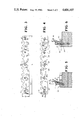
- FIG. 1 is a top plan view of the cylinder head of a Fiat engine of the type with which the present invention bar tool is designed to be used and illustrated after the camshaft housing has been removed.
- FIG. 2 is a top plan view, similar to that of FIG. 1 but with the head removal bar tool of the invention in place on the cylinder head.
- FIG. 3 is a top plan view of the elongated bar tool of the invention without its associated bolts used to remove the cylinder head.
- FIG. 4 is a bottom view of the FIG. 3 bar tool.
- FIG. 5 is a fragmentary section view taken along and in the direction of line 5--5 of FIG. 2 showing the bar tool mounted in place on a Fiat cylinder head prior to the head being removed from the engine block.
- FIG. 6 is a fragmentary section view similar to FIG. 5 but taken along the line 6--6 of FIG. 2.
- Cylinder head removal tool 10 made of tool steel comprises an elongated, flat, smooth bottomed surface bar tool 15, locking bolts 16 and pusher bolts 17.
- Bar tool 15 has a first series of angled threaded holes 18 passing through bar tool 15. The locations of holes 18 match the locations of angled threaded holes 19 in cylinder head 10 which are normally used to secure the camshaft housing to cylinder head 20.
- the underside of bar tool 15, adjacent each threaded hole 18, is flared outward as at 18a to aid in the locating and securement of bar tool 15 to cylinder head 20.
- holes 18 are angled at approximately 20° off vertical (FIG. 5) to match the angled orientation of threaded holes 19 in cylinder head 20.
- a second series of threaded, vertical holes 25 pass through bar tool 15 at locations matching the locations of studs 26 in the engine block and which pass through cylinder head 20. Cutouts 30 in bar tool 15 are provided and located to allow bar tool 15 to be positioned adjacent the valve springs (not shown).
- the length of bar tool 15 is substantially equal to the length of the cylinder head 20.
- the width of bar tool 15 is sufficient to provide a bearing surface of surrounding studs 26 when in use.
- the thickness of bar tool 15 is sufficient both for strength and for providing sufficient depth in holes 25 for receiving the threaded ends of studs 26 while still allowing enough depth for the pusher bolts 17 to engage the threads in holes 25.
- the inside diameter of threaded holes 25 is sufficient to allow the exposed threaded ends of studs 26 to loosely fit therein before being engaged by the pusher bolts 17.
- bar tool 15 was made of tool steel and had a length L of 19 inches, a width W of 2 inches and a thickness T of 9/16 inches.
- the camshaft housing (not shown) is first removed from the cylinder head 20 by removing bolts which hold the camshaft housing on the cylinder head 20.
- the bolts which are normally easy to remove and which secure the cylinder head 20 to the engine block on the front side of the engine are next removed.
- the nuts on the studs 26 which secure the cylinder head 20 to the engine block on the back side of the engine are next removed which exposes the upper threaded ends of the studs for placement in holes 25.
- bar tool 15 is placed on cylinder head 20 in the manner illustrated in FIG. 2 with the cutouts 30 positioned as illustrated.
- Pusher bolts 17 are next screwed into holes 25 and are screwed down until the ends of pusher bolts 17 firmly contact the top face of studs 26.
- the inside diameters of the threaded holes 25 are larger than the outside threaded diameters on the exposed ends of the studs which allows each bolt 17 to be tightened in its respective threaded hole 25 while allowing bar tool 15 to gradually move up and off the upper threaded ends of the studs 26.
- Pusher bolts 17 are gradually tightened down until studs 26 are unfrozen and cylinder head 20 begins to be forced upward on studs 26. By slowly alternating the loosening and tightening of different pusher bolts 17 in some appropriate pattern developed by experience cylinder head 20 is ultimately freed and raised without binding upon any of studs 26.
Abstract
A cylinder head removal tool is provided for removing the cylinder head from the engine block of an engine of the type used in a Fiat Model 128, 1300, 1500, or X-1.9. The tool comprises an elongated bar made of tool steel with means for bolting the bar to the cylinder head and for mounting pusher bolts which can be tightened down onto exposed threaded ends of frozen studs holding the cylinder head. As the bolts are tightened down onto the studs the cylinder head is gradually lifted upward free from the studs.
Description
1. Technical Field
The present invention relates to an automotive engine cylinder head removal tool. More specifically, the head removal tool of the invention is adapted for removal of the cylinder head of an engine such as used in the Fiat Models 128, 1300, 1500, or X-1.9 overhead cam engines with the studs on only one side of the engine block.
2. Background Art
Applicant has found that during the engine rebuilding procedure for four cylinder, single overhead cam Fiat 128, 1300, 1500, and X-1.9 overhead cam engines with the studs on only one side of the engine block, extreme difficulty is encountered in removing the engine cylinder head. Five bolts secure the cylinder head to the cylinder block on the front or carburetor side of the engine and five nuts on threaded studs secure the cylinder head to the cylinder block on the back or manifold side of the engine. The front head bolts are normally easy to remove since there is little or no corrosion and they are easy to reach. However, it is normally very difficult to remove the cylinder head from the shanks of the studs along the back side of the engine after the nuts have been removed from the upper ends of the studs. Sometimes one or all of the studs are frozen in the cylinder head which prevents removal of the head. The cylinder head is typically made of aluminum whereas the studs are typically made of steel. Corrosion between the steel studs and the aluminum cylinder head is caused by seepage of water about the studs. By being "frozen" is meant that the studs are effectively stuck in place and cannot be easily separated from the head. Attempts to forcefully remove the cylinder head from the engine block are very time consuming and it is often virtually impossible to remove the cylinder head from the engine block. Thus, there is a need for a tool to assist in this cylinder head removal operation and applicant is unaware of any tool of any kind adapted to this purpose.
The automobile cylinder head removal tool of the invention comprises an elongated metal bar of predetermined thickness and width and of a length which is roughly equal to the length of the cylinder head. The bar tool has a flat, smooth bottom surface and a first series of angled holes which are located so that they can be aligned with a series of angled holes in the cylinder head normally used for fastening the camshaft housing on the cylinder head. A second series of vertical threaded holes are provided in the bar tool which can be aligned with the studs used to hold the cylinder head on the engine block. Before the bar tool of the invention is used, the camshaft housing is removed from the cylinder head. Additionally, the bolts which secure the cylinder head on the front side of the engine are also removed and the nuts on the upper ends of the studs which secure the cylinder head to the engine block on the back side of the engine are also removed. The bar tool of the invention is then mounted on the cylinder head to be removed and threaded bolts are mounted in the first series of holes and secured to the camshaft housing mounting holes on the cylinder head so as to secure the bar tool to the cylinder head. Next, another set of threaded bolts are threaded into the second series of holes and are tightened in a selected pattern so that the cylinder head is gradually forced upward and away from any studs to which the cylinder head might have been frozen. Once any frozen studs have been broken away from the cylinder head, the entire cylinder head may then be raised from the engine block.
FIG. 1 is a top plan view of the cylinder head of a Fiat engine of the type with which the present invention bar tool is designed to be used and illustrated after the camshaft housing has been removed.
FIG. 2 is a top plan view, similar to that of FIG. 1 but with the head removal bar tool of the invention in place on the cylinder head.
FIG. 3 is a top plan view of the elongated bar tool of the invention without its associated bolts used to remove the cylinder head.
FIG. 4 is a bottom view of the FIG. 3 bar tool.
FIG. 5 is a fragmentary section view taken along and in the direction of line 5--5 of FIG. 2 showing the bar tool mounted in place on a Fiat cylinder head prior to the head being removed from the engine block.
FIG. 6 is a fragmentary section view similar to FIG. 5 but taken along the line 6--6 of FIG. 2.
With reference to the drawings, the cylinder head removal tool of the present invention is generally designated 10. Cylinder head removal tool 10 made of tool steel comprises an elongated, flat, smooth bottomed surface bar tool 15, locking bolts 16 and pusher bolts 17. Bar tool 15 has a first series of angled threaded holes 18 passing through bar tool 15. The locations of holes 18 match the locations of angled threaded holes 19 in cylinder head 10 which are normally used to secure the camshaft housing to cylinder head 20. The underside of bar tool 15, adjacent each threaded hole 18, is flared outward as at 18a to aid in the locating and securement of bar tool 15 to cylinder head 20. When in use, holes 18 are angled at approximately 20° off vertical (FIG. 5) to match the angled orientation of threaded holes 19 in cylinder head 20.
A second series of threaded, vertical holes 25 pass through bar tool 15 at locations matching the locations of studs 26 in the engine block and which pass through cylinder head 20. Cutouts 30 in bar tool 15 are provided and located to allow bar tool 15 to be positioned adjacent the valve springs (not shown).
The length of bar tool 15 is substantially equal to the length of the cylinder head 20. The width of bar tool 15 is sufficient to provide a bearing surface of surrounding studs 26 when in use. The thickness of bar tool 15 is sufficient both for strength and for providing sufficient depth in holes 25 for receiving the threaded ends of studs 26 while still allowing enough depth for the pusher bolts 17 to engage the threads in holes 25. As previously mentioned and as best illustrated in FIG. 6, the inside diameter of threaded holes 25 is sufficient to allow the exposed threaded ends of studs 26 to loosely fit therein before being engaged by the pusher bolts 17. In one embodiment bar tool 15 was made of tool steel and had a length L of 19 inches, a width W of 2 inches and a thickness T of 9/16 inches.
When bar tool 15 is used for the purpose of removing a cylinder head 20 from the engine block of a Fiat automobile engine, the camshaft housing (not shown) is first removed from the cylinder head 20 by removing bolts which hold the camshaft housing on the cylinder head 20. The bolts which are normally easy to remove and which secure the cylinder head 20 to the engine block on the front side of the engine are next removed. The nuts on the studs 26 which secure the cylinder head 20 to the engine block on the back side of the engine are next removed which exposes the upper threaded ends of the studs for placement in holes 25. Next, bar tool 15 is placed on cylinder head 20 in the manner illustrated in FIG. 2 with the cutouts 30 positioned as illustrated. In such position threaded holes 18 in bar tool 15 are aligned with cylinder head holes 19 and bar tool holes 25 are aligned with studs 26. The exposed threaded ends of studs 26 reside loosely within holes 25. Locking bolts 16 are now threaded into bar tool holes 18 and into holes 19 in cylinder head 20. Thus, bar tool 15 is held fixedly secured to cylinder head 20 by locking bolts 16. Recesses 27a, 27b on the bottom of bar tool 15 receive pins 28a, 28b.
Once free, cylinder head 20 is lifted off of the engine block by grasping the locking bolts 16 and lifting cylinder head 20. A heretofore troublesome and sometines virtually impossible task is thus accomplished easily with the use of applicant's new cylinder head removal tool 10.
Claims (1)
1. A tool for removing the cylinder head from the engine block of an engine of the Fiat model type 128, 1300, 1500, or X-1.9, said cylinder head mounting a series of upstanding valve springs and having a series of off-vertical threaded holes normally used for securing a camshaft housing and being released from securement to said block on one side by removal of a plurality of bolts and on an opposite side being secured to said block by a plurality of studs having their securing nuts removed and exposed threaded ends extending from the block above a flat bearing surface on the block with the shanks of the studs frozen in the cylinder head, comprising:
(a) an elongated bar having:
(i) a flat, smooth, bottom bearing surface;
(ii) a length substantially equal to the length of the cylinder head being removed;
(iii) a thickness in excess of the length of the exposed threaded ends of the studs securing the cylinder head to the engine block;
(iv) a width sufficient to provide a bearing surface surrounding each said exposed stud end when said bar is mounted on said cylinder head;
(v) a first series of threaded holes located on said bar in off-vertical relation to the plane of the bottom surface of said bar to mate said off-vertical series of threaded holes in said cylinder head normally used to secure said camshaft housing thereon;
(vi) a second series of threaded holes located on said bar in vertical relation to the plane of the bottom surface of said bar, said second series of threaded holes located on said bar being alignable with and adapted for loosely receiving the exposed threaded ends of said plurality of studs securing the cylinder head to the engine block; and
(vii) a series of arc-shaped cutouts along one side of said bar adapted to fit adjacent valve springs on said cylinder head;
(b) a first set of bolts threadably received by said first series of off-vertical threaded holes in said bar and screwed into said series of off-vertical threaded holes in said cylinder head to fixedly secure said bar to said cylinder head; and
(c) a second set of bolts threadably received by said second series of threaded holes in said bar and adapted to be screwed down onto the top faces of the exposed threaded ends of said studs so as to gradually force said cylinder head upward and free of the shanks of said studs as said second set of bolts are tightened down onto the said top faces of said exposed threaded ends of said studs.
Priority Applications (1)
| Application Number | Priority Date | Filing Date | Title |
|---|---|---|---|
| US06/738,341 US4606107A (en) | 1985-05-28 | 1985-05-28 | Automobile cylinder head removal tool |
Applications Claiming Priority (1)
| Application Number | Priority Date | Filing Date | Title |
|---|---|---|---|
| US06/738,341 US4606107A (en) | 1985-05-28 | 1985-05-28 | Automobile cylinder head removal tool |
Publications (1)
| Publication Number | Publication Date |
|---|---|
| US4606107A true US4606107A (en) | 1986-08-19 |
Family
ID=24967584
Family Applications (1)
| Application Number | Title | Priority Date | Filing Date |
|---|---|---|---|
| US06/738,341 Expired - Fee Related US4606107A (en) | 1985-05-28 | 1985-05-28 | Automobile cylinder head removal tool |
Country Status (1)
| Country | Link |
|---|---|
| US (1) | US4606107A (en) |
Cited By (4)
| Publication number | Priority date | Publication date | Assignee | Title |
|---|---|---|---|---|
| GB2279900A (en) * | 1993-06-22 | 1995-01-18 | Adrian Musgrove | Cylinder head puller |
| DE10360178A1 (en) * | 2003-12-20 | 2005-07-21 | Volkswagen Ag | Device to be used for separation of bearing frame from cylinder head, designed as frame with bores for insertion of spindles |
| CN107953293A (en) * | 2017-12-29 | 2018-04-24 | 安徽全柴动力股份有限公司 | A kind of engine camshaft cover Special tool for assembling |
| US10406663B2 (en) | 2015-12-10 | 2019-09-10 | Fanuc Corporation | Detachment tool and motor drive device provided with the same |
Citations (4)
| Publication number | Priority date | Publication date | Assignee | Title |
|---|---|---|---|---|
| US2618052A (en) * | 1950-09-15 | 1952-11-18 | John L Skaggs | Motor puller |
| US2684527A (en) * | 1951-05-21 | 1954-07-27 | Edward A Hedlund | Method of removing hubs |
| US3060558A (en) * | 1958-07-30 | 1962-10-30 | Sol J Levenson | Device for removing press fitted axle bearings |
| US4437220A (en) * | 1982-07-19 | 1984-03-20 | Gregory Oran A | Method and apparatus for dismounting trunnion bearings |
-
1985
- 1985-05-28 US US06/738,341 patent/US4606107A/en not_active Expired - Fee Related
Patent Citations (4)
| Publication number | Priority date | Publication date | Assignee | Title |
|---|---|---|---|---|
| US2618052A (en) * | 1950-09-15 | 1952-11-18 | John L Skaggs | Motor puller |
| US2684527A (en) * | 1951-05-21 | 1954-07-27 | Edward A Hedlund | Method of removing hubs |
| US3060558A (en) * | 1958-07-30 | 1962-10-30 | Sol J Levenson | Device for removing press fitted axle bearings |
| US4437220A (en) * | 1982-07-19 | 1984-03-20 | Gregory Oran A | Method and apparatus for dismounting trunnion bearings |
Cited By (5)
| Publication number | Priority date | Publication date | Assignee | Title |
|---|---|---|---|---|
| GB2279900A (en) * | 1993-06-22 | 1995-01-18 | Adrian Musgrove | Cylinder head puller |
| DE10360178A1 (en) * | 2003-12-20 | 2005-07-21 | Volkswagen Ag | Device to be used for separation of bearing frame from cylinder head, designed as frame with bores for insertion of spindles |
| US10406663B2 (en) | 2015-12-10 | 2019-09-10 | Fanuc Corporation | Detachment tool and motor drive device provided with the same |
| DE102016123295B4 (en) | 2015-12-10 | 2020-07-09 | Fanuc Corporation | Peeling tool |
| CN107953293A (en) * | 2017-12-29 | 2018-04-24 | 安徽全柴动力股份有限公司 | A kind of engine camshaft cover Special tool for assembling |
Similar Documents
| Publication | Publication Date | Title |
|---|---|---|
| US4707051A (en) | Tap connector | |
| US5004081A (en) | Battery restraint system | |
| US4606107A (en) | Automobile cylinder head removal tool | |
| US2568584A (en) | Fastening device | |
| DE59905190D1 (en) | DEVICE FOR ATTACHING A FIRST PART TO A FIXED SECOND PART | |
| US4790060A (en) | Method for holding a conduit to a channel | |
| US3656466A (en) | Fastener element and assembly | |
| WO1986005551A1 (en) | Apparatus and method of packaging an engine cylinder assembly | |
| US4649614A (en) | Method and apparatus for repair of flanged exhaust connections | |
| US4907301A (en) | Method for setting toilet bowls | |
| US2469441A (en) | Locking plate | |
| US6640670B2 (en) | Tool for engine crank shaft | |
| EP0076096B1 (en) | Fixing device for mounting a plate on the flange of a beam | |
| US4576308A (en) | Tank hatch opening obstructing construction | |
| US3362450A (en) | Tire chain assembly | |
| US5560269A (en) | Wrench for use with seized engine oil filter and method | |
| US4026337A (en) | Power tool | |
| US4534588A (en) | Engine lifting tool | |
| US6334375B1 (en) | Tool for engine crank shaft | |
| US4541158A (en) | Piston and connecting rod removing and installation tool | |
| US4457033A (en) | Adjustable combination lawn mower tool | |
| US5791627A (en) | Mounting system for automotive internal combustion engine | |
| US4684357A (en) | Timing chain retractor and lock | |
| GB1593545A (en) | Bolts | |
| US20110219598A1 (en) | Vertical mounted motor hoist |
Legal Events
| Date | Code | Title | Description |
|---|---|---|---|
| FPAY | Fee payment |
Year of fee payment: 4 |
|
| FPAY | Fee payment |
Year of fee payment: 8 |
|
| REMI | Maintenance fee reminder mailed | ||
| LAPS | Lapse for failure to pay maintenance fees | ||
| FP | Lapsed due to failure to pay maintenance fee |
Effective date: 19980819 |
|
| STCH | Information on status: patent discontinuation |
Free format text: PATENT EXPIRED DUE TO NONPAYMENT OF MAINTENANCE FEES UNDER 37 CFR 1.362 |