US4595180A - Spring assembly - Google Patents
Spring assembly Download PDFInfo
- Publication number
- US4595180A US4595180A US06/657,982 US65798284A US4595180A US 4595180 A US4595180 A US 4595180A US 65798284 A US65798284 A US 65798284A US 4595180 A US4595180 A US 4595180A
- Authority
- US
- United States
- Prior art keywords
- legs
- wire
- base frame
- corners
- grid
- Prior art date
- Legal status (The legal status is an assumption and is not a legal conclusion. Google has not performed a legal analysis and makes no representation as to the accuracy of the status listed.)
- Expired - Fee Related
Links
Images

Classifications
-
- A—HUMAN NECESSITIES
- A47—FURNITURE; DOMESTIC ARTICLES OR APPLIANCES; COFFEE MILLS; SPICE MILLS; SUCTION CLEANERS IN GENERAL
- A47C—CHAIRS; SOFAS; BEDS
- A47C23/00—Spring mattresses with rigid frame or forming part of the bedstead, e.g. box springs; Divan bases; Slatted bed bases
- A47C23/04—Spring mattresses with rigid frame or forming part of the bedstead, e.g. box springs; Divan bases; Slatted bed bases using springs in compression, e.g. coiled
- A47C23/043—Spring mattresses with rigid frame or forming part of the bedstead, e.g. box springs; Divan bases; Slatted bed bases using springs in compression, e.g. coiled using wound springs
- A47C23/0438—Spring mattresses with rigid frame or forming part of the bedstead, e.g. box springs; Divan bases; Slatted bed bases using springs in compression, e.g. coiled using wound springs of special shape
-
- A—HUMAN NECESSITIES
- A47—FURNITURE; DOMESTIC ARTICLES OR APPLIANCES; COFFEE MILLS; SPICE MILLS; SUCTION CLEANERS IN GENERAL
- A47C—CHAIRS; SOFAS; BEDS
- A47C23/00—Spring mattresses with rigid frame or forming part of the bedstead, e.g. box springs; Divan bases; Slatted bed bases
- A47C23/007—Edge stiffeners
-
- A—HUMAN NECESSITIES
- A47—FURNITURE; DOMESTIC ARTICLES OR APPLIANCES; COFFEE MILLS; SPICE MILLS; SUCTION CLEANERS IN GENERAL
- A47C—CHAIRS; SOFAS; BEDS
- A47C23/00—Spring mattresses with rigid frame or forming part of the bedstead, e.g. box springs; Divan bases; Slatted bed bases
- A47C23/02—Spring mattresses with rigid frame or forming part of the bedstead, e.g. box springs; Divan bases; Slatted bed bases using leaf springs, e.g. metal strips
Definitions
- the invention comprises a rigid rectangular base frame comprising spaced, parallel sides and ends, a rigid grid frame comprising a rectangular border wire and transversely and longitudinally-crossing grid wires attached at their ends to the border wire and at their crossings to each other and springs interposed between the base frame and grid frame including springs at the four corners structured when pressure is brought to bear on the grid frame to apply tension to the border wire in the plane of the grid frame and in directions bisecting the angles at the corners.
- the springs at the corners are bent wire springs and are secured at their lower ends to the base frame and at their upper ends to the border wire of the grid frame.
- the bent wire springs have upper and lower attaching members and a pair of side members, said side members being transversely symmetrical from side to side and asymmetrical from front to back so that pressure brought to bear on the upper ends tends to bend the springs in one direction as opposed to the other and in accordance with the invention, the springs are positioned at the corners so that the sides toward which the springs tend to bias face outwardly.
- the upper attaching elements of the springs comprise a straight length of wire having at its opposite ends diverging lengths of wire diverging at angles to the straight length of wire such that when the spring is placed astride a corner of the assembly with the straight length of wire diagonal to the corner, the diverging lengths of wire parallel the sides and ends of the border wire at the corner.
- the side members comprise first legs extending downwardly and forwardly relative to the upper attaching member toward each other and the second leg members extending upwardly and rearwardly relative to the lower attaching member away from each other. The first legs are disposed forwardly of the second legs.
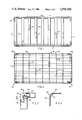
- FIG. 1 is a plan view of a rigid, rectangular base frame showing the spring units of this invention positioned at the four corners thereof;
- FIG. 2 is a plan view of a rectangular grid frame comprising a border wire and longitudinally and transversely-spaced grid wires attached thereto and to each other at their crossing with the spring units of this invention positioned at the four corners thereof;
- FIG. 3 is an enlarged plan view at the corner of the base frame showing the attaching of the lower end of a spring unit thereto;
- FIG. 4 is an enlarged plan view of the grid frame at a corner showing the attachment of the upper end of the spring unit thereto;
- FIG. 5 is a perspective view of one form of corner spring
- FIG. 6 is a side elevation of the spring shown in FIG. 5;
- FIG. 7 is a perspective view of another form of corner spring
- FIG. 8 is a side elevation of the spring shown in FIG. 7;
- FIG. 9 is a perspective view of still another form of corner spring.
- FIG. 10 is a side elevation of the spring shown in FIG. 9.
- FIG. 1 there is shown a rigid, rectangular base frame 10 comprising spaced, parallel sides 12-12 and spaced, parallel ends 14-14 connected at their ends to the spaced, parallel sides 12-12 and a plurality of longitudinally-spaced, parallel, transversely-extending support bars 16 secured at their ends to the sides 12-12.
- FIG. 2 shows a grid frame 18 comprising a border wire 20 having spaced, parallel sides 22-22 and ends 24-24 and a plurality of longitudinally and transversely-extending grid wires 26 secured at their ends to the sides and ends of the border wire and to each other at their crossings.
- the grid frame 18 is held in spaced, parallel relation to the base frame 10 by a plurality of spring units of suitable kind, as indicated generally by the reference character 27 disposed in transversely-spaced relation to each other with their lower ends secured to the support bars 16 and their upper ends secured to the grid wires 26.
- the spring units 27 may be coil springs or bent wire springs or a combination thereof.
- bent wire spring units 28 are positioned at the four corners of the composite structure with their lower ends secured to the base frame and their upper ends secured to the border wire, as will now be more specifically described with references to FIGS. 3 and 4.
- bent wire spring units 28 take several forms, as disclosed in FIGS. 5 to 10.
- bent wire spring units in the several forms illustrated have in common symmetry in one direction that is, transversely from one side to the other and asymmetry in a direction at right angles thereto that is, from front to back such that when pressure is brought to bear on the upper end of the spring unit, as indicated by the arrow A, it tends to bias or tilt in its asymmetrical dimension in a direction forwardly as indicated by the arrow B with respect to its lower end.
- This tendency to tilt due to the asymmetrical configuration of the spring unit is employed herein by positioning the spring units at the four corners of the assembly and securing the lower ends to the base frame and the upper ends to the border wire so that pressure brought to bear on the grid frame at the corners tends to impart tension to the border wire along its sides and ends, thus to counteract any tendency for the border wire to sag.
- the spring unit 28 in one form comprises a lower portion 30, an upper portion 32 and side portions 34-34 of bent wire construction which support the upper portion 32 for yielding movement toward the lower portion 30.
- the lower portion 30 comprises angularly-disposed legs 36-36 integrally joined at their forward ends at 38.
- the upper portion 32 comprises a substantially straight portion 40, at the opposite ends of which there are rearwardly-diverging portions 42-42.
- the side portions comprise legs 44 connected at their upper ends to the rear ends of the portions 42-42, at the lower ends of which there are laterally-extending arms 46-46.
- the side portions also include upwardly-extending legs 48-48 connected at their lower ends to the rear ends of the legs 36-36 provided with horizontal, forwardly-extending arms 50-50.
- the arms 46-46 and 50-50 are connected by legs 52-52.
- the legs 44-44 extend forwardly relative to the lower part and toward each other.
- the legs 48-48 extend upwardly and away from each other.
- the arms 46-46 and 50-50 are horizontal and the legs 52-52 diverge and are substantially parallel to the legs 48-48. Pressure brought to bear on the portion 40 at the top will tilt the top forwardly relative to the bottom.
- the structure thus described is disposed at the corner of the spring assembly as shown in FIG. 3 with its lower end attached to the base frame and so oriented that the divergent parts 42-42 at the upper end parallel the border wire, FIGS. 3 & 4.
- the divergent parts 42-42 are secured to the border wire by clips 54-54, FIG. 4.
- the upper part 40 extends diagonally of the corner and the apex 38 of the converging parts 36-36 at the bottom is disposed toward the corner.
- Pressure brought to bear on the grid frame tends to tilt the top of the spring unit outwardly relative to the bottom and thus impart tension to the border wire along its sides and ends.
- bent wire spring units disclosed in FIGS. 7, 8, 9 and 10 may optionally be used in lieu of that shown in FIGS. 5 and 6 to achieve the same purpose, to wit, the tensioning of the border wire when pressure is brought to bear on the grid frame.
- the bent wire spring unit 28' comprises a lower part 62, an upper part 64 and side parts 66-66.
- the lower part 62 comprises diverging parts 68-68 integrally connected at their forward ends at 70.
- the upper part 64 comprises a straight length 72 at the opposite ends of which there are diverging parts 74-74.
- the side parts 66-66 comprise legs 76-76 connected at their upper ends to the rear ends of the parts 74-74 and arms 78-78 connected to their lower ends and legs 80-80 extending upwardly from the rear ends of the parts 68-68 provided with arms 82-82 at their upper ends.
- the arms 78-78 and 82-82 are connected by legs 84-84.
- the legs 76-76 extend downwardly and forwardly away from each other.
- the legs 80-80 extend upwardly substantially perpendicularly and toward each other.
- the arms 78-78 and 82-82 are substantially horizontal and at right angles to each other and the legs 84-84 are parallel to the legs 80-80.
- the bent wire spring unit 28" shown in FIGS. 9 and 10 comprises a lower part 88, an upper part 90 and side parts 92-92.
- the lower part 88 comprises diverging arms 94-94 integrally connected at their forward ends at 96.
- the upper part 90 comprises straight portions 98-98, at the ends of which there are diverging parts 100-100.
- the side parts 92-92 comprise downwardly-extending legs 102-102 integrally connected at their upper ends to the rear ends of the parts 100-100, at the lower ends of which there are arms 104-104 and upwardly-extending legs 106-106 connected at their lower ends to the rear ends of the parts 94-94 and arms 108-108 at their upper ends.
- the arms 104-104 and 108-108 are connected to each other.
- the legs 102-102 extend downwardly, forwardly and toward each other and the legs 106-106 extend upwardly nearly perpendicularly and away from each other.
- the arms 104-104 and 108-108 are at right angles to each
- the lower ends of the spring units are attached to the sides and ends of the base frame at the corners by staples and are attached at their upper ends to the grid wire by crimped clips 54, FIGS. 3 and 4.
- spring units at the corners are so structured as to impart tension to the sides and ends of the border wire.
- the spring units interposed between the base frame and grid frame longitudinally and transversely thereof intermediate the spring units at the corners may be of any desired configuration, either the same as that described in FIGS. 5 and 10 or of some other configuration of the bent wire type or the coiled wire type.
Abstract
Description
Claims (5)
Priority Applications (1)
| Application Number | Priority Date | Filing Date | Title |
|---|---|---|---|
| US06/657,982 US4595180A (en) | 1984-10-05 | 1984-10-05 | Spring assembly |
Applications Claiming Priority (1)
| Application Number | Priority Date | Filing Date | Title |
|---|---|---|---|
| US06/657,982 US4595180A (en) | 1984-10-05 | 1984-10-05 | Spring assembly |
Publications (1)
| Publication Number | Publication Date |
|---|---|
| US4595180A true US4595180A (en) | 1986-06-17 |
Family
ID=24639420
Family Applications (1)
| Application Number | Title | Priority Date | Filing Date |
|---|---|---|---|
| US06/657,982 Expired - Fee Related US4595180A (en) | 1984-10-05 | 1984-10-05 | Spring assembly |
Country Status (1)
| Country | Link |
|---|---|
| US (1) | US4595180A (en) |
Cited By (8)
| Publication number | Priority date | Publication date | Assignee | Title |
|---|---|---|---|---|
| US4684111A (en) * | 1986-02-14 | 1987-08-04 | Webster Spring Co. Inc. | Bent wire spring module |
| US4730357A (en) * | 1987-03-17 | 1988-03-15 | Leggett & Platt, Incorporated | Bedding box spring |
| US4770397A (en) * | 1986-10-06 | 1988-09-13 | Steadley Company | Spring wire element for foundation unit |
| US5316375A (en) * | 1991-12-16 | 1994-05-31 | Buddy Orthopoedic Inc. | Back support and internal frame |
| US5499414A (en) * | 1994-05-05 | 1996-03-19 | Simmons Company | Innerspring construction including improved edge characteristics |
| US20070174961A1 (en) * | 2006-02-01 | 2007-08-02 | Hickory Springs Manufacturing Company | Bedding foundation support module |
| US20070180614A1 (en) * | 2006-02-01 | 2007-08-09 | Hickory Springs Manufacturing Company | Bedding foundation support module |
| USD883002S1 (en) * | 2017-03-20 | 2020-05-05 | L&P Property Management Company | Continuous spring |
Citations (3)
| Publication number | Priority date | Publication date | Assignee | Title |
|---|---|---|---|---|
| US3286281A (en) * | 1965-02-24 | 1966-11-22 | Hoover Ball & Bearing Co | Box spring assembly |
| US4101992A (en) * | 1977-02-17 | 1978-07-25 | Webster Spring Co. Inc. | Spring assembly with reinforcement |
| US4452438A (en) * | 1982-01-29 | 1984-06-05 | Hoover Universal, Inc. | Box spring assembly with improved corner springs |
-
1984
- 1984-10-05 US US06/657,982 patent/US4595180A/en not_active Expired - Fee Related
Patent Citations (3)
| Publication number | Priority date | Publication date | Assignee | Title |
|---|---|---|---|---|
| US3286281A (en) * | 1965-02-24 | 1966-11-22 | Hoover Ball & Bearing Co | Box spring assembly |
| US4101992A (en) * | 1977-02-17 | 1978-07-25 | Webster Spring Co. Inc. | Spring assembly with reinforcement |
| US4452438A (en) * | 1982-01-29 | 1984-06-05 | Hoover Universal, Inc. | Box spring assembly with improved corner springs |
Cited By (10)
| Publication number | Priority date | Publication date | Assignee | Title |
|---|---|---|---|---|
| US4684111A (en) * | 1986-02-14 | 1987-08-04 | Webster Spring Co. Inc. | Bent wire spring module |
| US4770397A (en) * | 1986-10-06 | 1988-09-13 | Steadley Company | Spring wire element for foundation unit |
| US4730357A (en) * | 1987-03-17 | 1988-03-15 | Leggett & Platt, Incorporated | Bedding box spring |
| US5316375A (en) * | 1991-12-16 | 1994-05-31 | Buddy Orthopoedic Inc. | Back support and internal frame |
| US5499414A (en) * | 1994-05-05 | 1996-03-19 | Simmons Company | Innerspring construction including improved edge characteristics |
| US20070174961A1 (en) * | 2006-02-01 | 2007-08-02 | Hickory Springs Manufacturing Company | Bedding foundation support module |
| US20070180614A1 (en) * | 2006-02-01 | 2007-08-09 | Hickory Springs Manufacturing Company | Bedding foundation support module |
| US7356859B2 (en) | 2006-02-01 | 2008-04-15 | Hickory Springs Manufacturing Company | Bedding foundation support module |
| US7360263B2 (en) | 2006-02-01 | 2008-04-22 | Hickory Springs Manufacturing Company | Bedding foundation support module |
| USD883002S1 (en) * | 2017-03-20 | 2020-05-05 | L&P Property Management Company | Continuous spring |
Similar Documents
| Publication | Publication Date | Title |
|---|---|---|
| CA1178379A (en) | Box spring assembly with improved corner springs | |
| US4577841A (en) | Bent wire spring unit | |
| US4595180A (en) | Spring assembly | |
| US4770397A (en) | Spring wire element for foundation unit | |
| US4559654A (en) | Bedding units and components for such units | |
| US3835485A (en) | Box spring assembly | |
| US4675927A (en) | Bedding units and springs therefor | |
| US5197155A (en) | Foundation unit with snap-fit modular springs | |
| US4779293A (en) | Formed wire box spring with spring wire deck | |
| US5497979A (en) | Foundation unit, wire element for the foundation unit, and method of forming the foundation unit | |
| US4595181A (en) | Bent wire spring unit | |
| US5005809A (en) | Spring element for a foundation unit and foundation unit employing a spring element | |
| US4730358A (en) | Sinuous spring module box spring assembly | |
| US5142715A (en) | Foundation unit with snap-fit modular springs | |
| US4699362A (en) | Spring element | |
| CA1240416A (en) | Combined bed frame and box spring assembly | |
| US2835314A (en) | Wire spring structure | |
| US5142716A (en) | Foundation unit with snap-fit modular springs | |
| US5964453A (en) | Wire grid and wire spring module for use with a furniture spring assembly | |
| US5558315A (en) | Multi-fold interlockable spring for use in mattress foundation assemblies | |
| US4721290A (en) | Bent wire spring unit | |
| US5369822A (en) | Bent wire spring module | |
| US6419212B1 (en) | Modular spring for a mattress foundation unit | |
| US4703527A (en) | Bedding springs and bedding units | |
| US6338174B1 (en) | Spring mattress |
Legal Events
| Date | Code | Title | Description |
|---|---|---|---|
| AS | Assignment |
Owner name: WEBSTER SPRING CO. INC. OXFORD,MA 01540 A MA CORP Free format text: ASSIGNMENT OF ASSIGNORS INTEREST.;ASSIGNOR:HAGEMEISTER, ROBERT C.;REEL/FRAME:004323/0219 Effective date: 19840925 |
|
| FEPP | Fee payment procedure |
Free format text: PAT HLDR NO LONGER CLAIMS SMALL ENT STAT AS SMALL BUSINESS (ORIGINAL EVENT CODE: LSM2); ENTITY STATUS OF PATENT OWNER: LARGE ENTITY |
|
| FEPP | Fee payment procedure |
Free format text: PAYOR NUMBER ASSIGNED (ORIGINAL EVENT CODE: ASPN); ENTITY STATUS OF PATENT OWNER: LARGE ENTITY |
|
| FPAY | Fee payment |
Year of fee payment: 4 |
|
| AS | Assignment |
Owner name: LEGGETT & PLATT, INCORPORATED, MISSOURI Free format text: ASSIGNMENT OF ASSIGNORS INTEREST.;ASSIGNOR:WEBSTER SPRING CO. INC.;REEL/FRAME:006357/0522 Effective date: 19911001 |
|
| FPAY | Fee payment |
Year of fee payment: 8 |
|
| AS | Assignment |
Owner name: L & P PROPERTY MANAGEMENT COMPANY, ILLINOIS Free format text: ASSIGNMENT OF ASSIGNORS INTEREST;ASSIGNOR:LEGGETT & PLATT, INCORPORATED;REEL/FRAME:007312/0104 Effective date: 19911001 |
|
| REMI | Maintenance fee reminder mailed | ||
| LAPS | Lapse for failure to pay maintenance fees | ||
| FP | Lapsed due to failure to pay maintenance fee |
Effective date: 19980617 |
|
| STCH | Information on status: patent discontinuation |
Free format text: PATENT EXPIRED DUE TO NONPAYMENT OF MAINTENANCE FEES UNDER 37 CFR 1.362 |