US4592573A - Three-dimensional pop-up message display stationery - Google Patents
Three-dimensional pop-up message display stationery Download PDFInfo
- Publication number
- US4592573A US4592573A US06/601,977 US60197784A US4592573A US 4592573 A US4592573 A US 4592573A US 60197784 A US60197784 A US 60197784A US 4592573 A US4592573 A US 4592573A
- Authority
- US
- United States
- Prior art keywords
- sheet
- panel
- segments
- stationery
- fold line
- Prior art date
- Legal status (The legal status is an assumption and is not a legal conclusion. Google has not performed a legal analysis and makes no representation as to the accuracy of the status listed.)
- Expired - Lifetime
Links
Images


Classifications
-
- G—PHYSICS
- G09—EDUCATION; CRYPTOGRAPHY; DISPLAY; ADVERTISING; SEALS
- G09F—DISPLAYING; ADVERTISING; SIGNS; LABELS OR NAME-PLATES; SEALS
- G09F1/00—Cardboard or like show-cards of foldable or flexible material
- G09F1/04—Folded cards
-
- B—PERFORMING OPERATIONS; TRANSPORTING
- B42—BOOKBINDING; ALBUMS; FILES; SPECIAL PRINTED MATTER
- B42D—BOOKS; BOOK COVERS; LOOSE LEAVES; PRINTED MATTER CHARACTERISED BY IDENTIFICATION OR SECURITY FEATURES; PRINTED MATTER OF SPECIAL FORMAT OR STYLE NOT OTHERWISE PROVIDED FOR; DEVICES FOR USE THEREWITH AND NOT OTHERWISE PROVIDED FOR; MOVABLE-STRIP WRITING OR READING APPARATUS
- B42D15/00—Printed matter of special format or style not otherwise provided for
Definitions
- This invention relates to folded stationery, paper sheets, cards, or the like, incorporating three-dimensional pop-up erectable indicia, such as letters, numbers or pictorial shapes, positioned along an interior fold, which are collapsed flat as the stationery is folded for mailing and storage, and are erected 3-D fashion for upstanding display in front of the normal front faces of the stationery as it is unfolded for examination by the sender or recipient, providing an attention-getting message permanently displayed by the stationery.
- three-dimensional pop-up erectable indicia such as letters, numbers or pictorial shapes
- a striking impact is created upon the mind of the viewer by individual free-standing letters displayed substantially spaced forward, in front of the normal front surface of a folded greeting card or a folded sheet of stationery. This creates the illusion that the message thus delivered by a missive of the present invention is carved from stone or other blocks of solid material.
- the free-standing arrayed sequences of pictorial shapes such as alphabetical letters characterizing the present invention are spaced well forward of a fold in the greeting card or sheet of folded stationery, apparently resting on or growing upward from the lower stationery panel beneath the fold, with narrow webs bridging the space between the upper edges of the arrayed letters and the upper stationery panel above the fold, which is embraced by and hidden behind the message-bearing letter array.
- the bridging webs themselves are formed in the shape of an arrayed sequence of alphabetical letters providing an additional line of message-bearing indicia.
- the letters and bridging webs of the invention may be formed directly by stamping from the foldable stationery blank itself, and in one form of the invention the letters and bridging webs are formed from a separate display panel having adhesive tabs for direct adherence to the foldable stationery sheet along one of its interior folds.
- Such separate collapsible and erectable message displays make it possible for the user to "build his own" pop-up message display stationery.
- individual letter pop-ups having adhesive tabs for mounting at the interior fold of a sheet of stationery allow the user to mount and display his own custom-made pop-up message, his initials, or any other display desired. Harmonizing or contrasting colors for the letters and the background, the reverse side of the mounting tabs, provide an eye-catching contrast to the color of the stationery sheet, if desired.
- a principal object of the present invention is to provide a folded advertising or promotional card, direct mail notice, greeting card or stationery sheet displaying upstanding, arrayed sequences of pictorial symbols conveying a message to the viewer, positioned in front of the normal face of the folded card or sheet.
- Another object of the invention is to provide such arrayed sequences of symbols or letters formed from the stationery sheet itself by removing therefrom the spaces between the letters and their positioning bridge webs.
- Still another object of the invention is to form such collapsible and erectable rows of letters and bridge webs in an array forming with the supporting fold-joined stationery panels a collapsible structure having a parallelogram cross-section, assuring its reliable collapse and erection with every folding and unfolding flexture of the supporting folded stationery sheet about the fold line along which the letters are positioned.
- a further object of the invention is to provide such upstanding arrays of letters and support panels as a separate collapsible unit which may be secured by adhesive to any folded sheet of stationery along a fold line thereof.
- a still further object of the invention is to provide such separate letter arrays with self-adhesive supporting tabs protected by peelable backing strips for convenient selection and mounting by the user at any desired location along an interior fold of any sheet of stationery.
- Another object of the invention is to provide a foldable card or sheet which is conveniently inserted in and typed upon by a typewriter or computer printer and then quickly decorated with a separate pop-up three-dimensional message-bearing insert adhesively secured to the card or sheet along an internal fold line.
- FIG. 1 is a perspective view of a folded stationery sheet incorporating an arrayed sequence of pop-up letters positioned in erectable configuration along each side of an interior fold line;
- FIG. 2 is a perspective view of a double-folded sheet or stationery with one panel having a protruding tab that can be gummed or adapted to receive a wafer seal for forming a self-sealing envelope, and incorporating an arrayed sequence of letters formed directly from the stationery sheet along a fold line by cutting the spaces therebetween away from the stationery sheet;
- FIG. 3 is a reduced size plan view of the unfolded sheet of FIG. 2 showing die-cut spaces removed therefrom between the letters along a fold line to form the display illustrated in FIG. 2;
- FIG. 4 is a fragmentary perspective view of the embodiment of FIG. 2 in the process of being folded to form a self-sealing envelope showing the arrayed sequence of letters in its collapsing position;
- FIG. 5 is a perspective view of a folding stationery sheet with a self-sealing envelope tab, similar to the embodiment shown in FIG. 2, and incorporating a "double-deck" series of arrayed sequences of letters forming a two-line display standing out before the front surfaces of the folded stationery sheet along an interior fold line;
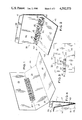
- FIG. 6 shows a separate die-cut blank for an insert incorporating an arrayed series of letters with bridging webs extending foldably from their upper edges toward and joined at a fold line to a rear mounting panel, and with their lower edges being joined along a fold line to a base mounting panel;
- FIG. 7 is a perspective view of the insert of FIG. 6 formed in its erected configuration for mounting on a sheet of stationery;
- FIG. 8 is a fragmentary perspective view of a stationery sheet showing the insert of FIG. 6 with its self-adhesive base panel mounted on the sheet adjacent to the fold line;
- FIG. 9 is a corresponding fragmentary perspective view of the insert of FIG. 6 with its rear mounting panel adhesively secured to the stationery sheet on the opposite side of the fold line from its base panel, forming the completed display structure illustrated in the embodiment of FIG. 1;
- FIG. 10 is a top plan view of a similar separate die-cut blank for an insert having a scored, double-width base panel;
- FIG. 11 is a perspective view of the insert of FIG. 10 in the process of being folded for assembly
- FIG. 12 is a perspective view of the insert of FIG. 10 in its assembled and glued erect condition with a peelable backing strip in the process of being removed from its double-width base panel;
- FIG. 13 is fragmentary perspective view showing the insert of FIG. 10 mounted along the interior fold line of a folded stationery sheet.
- FIGS. 14 through 17 are diagrammatic end elevation views showing the insert of FIG. 10 in various stages of its assembly, insertion, and mounting along the interior fold of a supporting stationery sheet.
- all embodiments of the invention present an arrayed series of symbols, numbers, letters or comparable message-carrying indicia, such as company logos, displayed pop-up fashion along an interior fold of a sheet of stationery, and positioned in front of the stationery sheet by bridge web means, formed as individual separate webs in the case of an arrayed series of alphabetical letters, extending from the upper edge of each letter to the stationery sheet behind the letter.
- bridge webs themselves are formed in the shape of a separate row of letters producing two arrayed sequences of letters positioned one above the other to form a double-line message.
- the decorative message-bearing indicia protrude from the stationery in front of a fold line, being mounted on or comprising a parallelogram support which may be formed from the stationery itself, in the case of the die-cut letters illustrated in FIGS. 2 and 3.
- the parallelogram support may be formed as a separate die-cut insert incorporating the pictorial cutouts or letters and their bridge webs combined with a rear mounting panel and a base mounting panel preferably secured by adhesive to the foldable stationery sheet, with the mounting panels flanking an interior fold line of the stationery sheet, thus causing the parallelogram to flex and collapse when the stationery is folded about its fold lines.
- die-cut inserts can be purchased in quantities by the consumer and individually mounted on any folded piece of stationery desired at any time.
- the stationery sheet 30 is provided with a pair of fold lines 31 and 32 which can be scored or precisely folded by hand or machine dividing the sheet 30 into three panels: an upper panel 33, a center panel 34, and a lower panel 36. Juxtaposed with the mid-portion of the upper transverse fold line 31 is a die-cut insert 37, such as the insert shown in the form of a die-cut blank 58 in FIG. 6 or the similar insert 71 of FIG. 10.
- the pop-up stationery 38 in FIG. 2 incorporates a double-folded sheet with a protruding sealing tab 39 to produce a self-sealing envelope formed of the folded stationery itself, and with the inner folded half-sheet having its fold line cut away by a series of die cutouts, leaving in place an arrayed sequence of letters and bridge webs which may all be everted to form the pop-up message display, as shown in FIG. 2.
- the blank of FIG. 3 from which the embodiment of FIG.
- the double-folded stationery sheet 38 has four panels or segments: (1) an upper back panel 41 from which gummed tab 39 protrudes upward; (2) a lower back panel 42 joined to upper back 41 by a contiguous fold line 43 forming the lower edge of upper panel 41 and the upper edge of lower panel 42; (3) an upper front panel 46; and (4) a lower front panel 47, contiguously joined along the left edge of panels 41 and 42, which is formed as a fold line 44.
- fold line 43 across the blank between upper front panel 46 and lower front panel 47 provides the location for the series of die cutouts 48 between the various strips forming bridge web sheet segments 49 extending from upper front panel 46 to the upper edges of the arrayed sequence of letter sheet segments 51, whose lower edges are foldably joined to the lower front panel 47, the spaces between letters 51 being die cutouts 52.
- the similar double-folded sheet 53 shown in FIG. 5, has the same panels 41, 42, 46, and 47 and same sealing tab 39, but it differs from double-folded stationery sheet 38 in having a double row of message-bearing letters forming the die-cut protruding everted sheet segments 56 and 57, positioned along its internal fold between panels 46 and 47.
- upstanding letters 56 forming the lower row of indicia-bearing symbols are separated by die cutouts 52, like letters 51 in FIG. 2.
- the bridge webs are formed as the upper row of letters 57 joined at their forward edges along a fold line to the upper edge of the lower row of letters 56, and having rear edges foldably joined to upper front panel 46, as shown in FIG. 5.
- the double rows 56 and 57 of message-bearing letters can also be formed as an insert like insert 37 illustrated in FIG. 1.
- FIGS. 6-13 provide unusually versatile flexibility for the stationery of the present invention, since they may have adhesive surfaces protected by peelable backing strips or registered pre-glueing needing re-moistening, allowing the user to mount them wherever desired.
- letters 51 and bridge webs 49 are formed by having their intervening spaces 48 and 52 removed by die cutting them from the insert blank 58, whose uppermost portion is formed as a rear mounting panel 59, having its top face coated with self-adhesive 61, as illustrated in FIG. 8, covered by a peelable backing strip 62, shown being lifted and peeled away in FIG. 8.
- the lower portion of blank 58 is formed as a base panel 63, likewise coated with a self-adhesive coating 64, which is also covered by a peelable backing strip 66, shown in the process of being peeled away in FIGS. 6 and 7.
- the flat blank 58 shown in FIG. 6, is foldable along three fold lines.
- the central fold line 67 joins the tops of letters 51 to the forward ends of bridge webs 49.
- the upper fold line 68 joins the rearmost or uppermost ends of bridge webs 49 to the contiguous edge of rear panel 59.
- the lower fold line 69 provides the hinge line along which the lower edge of the letters 51 are foldably joined to the upper edge of base panel 63.
- the die-cut insert blank 58 of FIG. 6 with its mounting panels being coated with moistenable glue or adhesive 61 and 64 is folded along its fold lines 67, 68 and 69 into a parallelogram cross-section shape for mounting on a sheet or stationery, in the configuration shown in FIG. 7, where its parallelogram shape is seen in perspective.
- the rear mounting panel 59 and the base mounting panel 63 are brought into close proximity, with their free edges juxtaposed.
- the insert is moved into position, with the free edge of its base panel 63 closely adjacent to the fold line 31 between upper panel 33 and center panel 34 of the stationery sheet 30, where its self-adhesive face adheres to panel 34, positioning the insert at the desired location beside fold line 31.
- the peelable backing strip 62 is then removed from the self-adhesive coating 61 of rear mounting panel 59, as indicated in FIG. 8, or adhesive coating 64 is re-moistened if required.
- the rear mounting panel 59 is then folded down toward fold line 31 into juxtaposition with base panel 63, as indicated in FIGS. 7 and 9, and its adhesive coating 61 adheres to top panel 33 of stationery sheet 30.
- the pop-up message-bearing insert is permanently positioned along the fold line 31 and easily collapsed, as indicated in FIG. 4, when the stationery sheet is folded.
- the message is automatically erected and conveniently displayed in a striking, three-dimensional manner.
- the alternative die-cut insert embodiment 71, shown in FIGS. 10-17 is very similar to the die-cut insert made from blank 58, shown in FIGS. 6-9.
- Blank 71 has a base panel 72 which is substantially double the width of base panel 63 of blank 58, shown in FIG. 6.
- the double width base panel 72 is preferably provided with a double width peelable backing strip 73, as shown in FIG. 10.
- FIGS. 11-17 One preferred technique for assembling the die-cut insert of 71 of FIG. 10 is illustrated in FIGS. 11-17. As shown in FIGS. 11 and 14, the removal of peelable backing strip 62 from the adhesive 61 on rear mounting panel 59 exposes the adhesive 61 ready for adherence to the reverse side of the distal half 72A of the double-width base panel 72, which is joined to the proximal half 72B of base panel 72 by an extra scored fold line 70.
- the lower edge of the arrayed sequence of letters 51 is joined by the same fold line 69 to the adjoining edge of proximal segment 72B of the double-width base panel 72, and the upper edge of letters 51 is joined by fold line 67 to bridge webs 49 whose opposite ends are joined by fold line 68 to rear mounting panel 59, all as shown in FIGS. 10 and 14.
- Peelable backing strip 73 is shown being peeled away at the righthand end of FIG. 10, revealing the underlying adhesive 74 coating the entire double-width base mounting panel 72.
- the assembly of the blank 71 to form the die-cut insert shown in FIG. 13 is preferably accomplished by leaving scored fold lines 67 and 70 substantially flat and unflexed, while infolding rear mounting panel 59 about its fold line 68 by approximately 180 degrees and removing the peelable backing strip 62 from its adhesive coating 61, as shown in FIGS. 11-14.
- the blank is then flexibly folded about fold line 69, causing the letters 51 and bridge webs 49 to pivot together about fold line 69, bringing adhesive coating 61 into adhering, bonding relationship with the reverse side of distal segment 72A of double-width base mounting panel 72.
- This operation is most conveniently performed utilizing a table 76 or a similar flat work surface on which the face of peelable backing strip 73 can be placed to support the blank while the foregoing folding operations are performed.
- force represented by arrow 77 in FIG.
- the double-width peelable backing strip 73 is then removed from the wide base mounting panel 72, exposing the adhesive coating 74 thereon.
- the fold lines 68 and 69 are then brought toward each other by collapsing the parallelogram toward the position shown in FIG. 16, causing fold lines 70 and 67 to be spread further apart, and the partially collapsed parallelogram insert is then lowered into position near the fold line 31 between panels 33 and 34 of stationery sheet 30 toward the seated position shown in FIG. 16, with fold line 70 of the sition shown in FIG. 16, with fold line 70 of the line 31 of stationery sheet 30.
- the proximal portion of adhesive coating 74 is bonded to stationery panel 34, anchoring the parallelogram insert 71 in the position shown in FIG. 16, while the distal portion of adhesive coating 74 is exposed, facing upper panel 33 of stationery sheet 30.
- insert blank 71 may be pre-assembled and stored flat, for selection by the user who merely moistens or peels the peelable strips from the adhesive and mounts the insert wherever desired.
Landscapes
- Physics & Mathematics (AREA)
- General Physics & Mathematics (AREA)
- Engineering & Computer Science (AREA)
- Theoretical Computer Science (AREA)
- Toys (AREA)
Abstract
Description
Claims (10)
Priority Applications (1)
| Application Number | Priority Date | Filing Date | Title |
|---|---|---|---|
| US06/601,977 US4592573A (en) | 1984-04-19 | 1984-04-19 | Three-dimensional pop-up message display stationery |
Applications Claiming Priority (1)
| Application Number | Priority Date | Filing Date | Title |
|---|---|---|---|
| US06/601,977 US4592573A (en) | 1984-04-19 | 1984-04-19 | Three-dimensional pop-up message display stationery |
Publications (1)
| Publication Number | Publication Date |
|---|---|
| US4592573A true US4592573A (en) | 1986-06-03 |
Family
ID=24409483
Family Applications (1)
| Application Number | Title | Priority Date | Filing Date |
|---|---|---|---|
| US06/601,977 Expired - Lifetime US4592573A (en) | 1984-04-19 | 1984-04-19 | Three-dimensional pop-up message display stationery |
Country Status (1)
| Country | Link |
|---|---|
| US (1) | US4592573A (en) |
Cited By (21)
| Publication number | Priority date | Publication date | Assignee | Title |
|---|---|---|---|---|
| US5022681A (en) * | 1989-09-21 | 1991-06-11 | Christopher Crowell | Paper pop-up devices and method of making the same |
| GB2244024A (en) * | 1990-05-18 | 1991-11-20 | Charles Howard Ensor | Greetings card or other display device |
| US5333909A (en) * | 1989-07-06 | 1994-08-02 | Hedge Jr J Richard | Promotional advertising brochure including reusable envelope device |
| WO1996008372A1 (en) * | 1994-09-12 | 1996-03-21 | Papermasters, Inc. | Pop-up promotional items and methods of making |
| US5588233A (en) * | 1994-08-05 | 1996-12-31 | Volkert, Inc. | Paper product and method of making |
| US5687495A (en) * | 1995-04-07 | 1997-11-18 | Papermasters, Inc. | Pop-up items having pressure-sensitive adhesive |
| US5738221A (en) * | 1995-06-09 | 1998-04-14 | Popshots Intellectual Property, Llc | Compact disc holder package containing a three-dimensional pop-up display |
| US5813596A (en) * | 1996-01-23 | 1998-09-29 | Dixonweb Printing Company | Pop-up advertising device and method |
| US5871828A (en) * | 1990-01-10 | 1999-02-16 | Papermaster, Inc. | Pop-up promotional items |
| US5887366A (en) * | 1994-08-05 | 1999-03-30 | Volkert, Inc. | Paper product and method of making |
| US6068903A (en) * | 1992-12-30 | 2000-05-30 | Papermasters, Inc. | Pop-up promotional items |
| US6311142B1 (en) * | 1999-01-15 | 2001-10-30 | Microsoft Corporation | Methods for designing pop-up cards, and cards produced thereby |
| US6386370B1 (en) | 2000-06-20 | 2002-05-14 | Quebecor World (Usa) Inc. | Tiered shadowbox pop-up structures |
| US7306262B1 (en) * | 1999-05-20 | 2007-12-11 | Electronic Forms Plus, Inc. | Single-sheet registration form and key packet |
| US20080081536A1 (en) * | 2006-06-02 | 2008-04-03 | Julian Payne | Playsets with pop-up structures |
| US20090206148A1 (en) * | 2008-02-19 | 2009-08-20 | Jenkins Kaluve D | Envelope with interior decorative elements |
| US7618301B2 (en) | 2005-06-03 | 2009-11-17 | Mattel, Inc. | Fold-out playsets with pop-up structures |
| US8251224B2 (en) | 2006-05-25 | 2012-08-28 | Mattel, Inc. | Product packaging with expanding structures |
| US20130192103A1 (en) * | 2010-11-05 | 2013-08-01 | American Greetings Corporation | Motion greeting cards |
| US20130265707A1 (en) * | 2012-04-10 | 2013-10-10 | Edgar Davin Salatandre | Business card assembly |
| US20230391128A1 (en) * | 2022-06-07 | 2023-12-07 | Hallmark Cards, Incorporated | Greeting card for automated printing |
Citations (5)
| Publication number | Priority date | Publication date | Assignee | Title |
|---|---|---|---|---|
| DE513339C (en) * | 1929-02-01 | 1930-11-26 | Stephen Louis Giraud | Book with collapsible models |
| US2458879A (en) * | 1949-01-11 | Manufacture of integral | ||
| US2609639A (en) * | 1950-11-29 | 1952-09-09 | Barker Alvin | Greeting card or folder |
| FR1373142A (en) * | 1963-08-10 | 1964-09-25 | Calendar | |
| US4146983A (en) * | 1975-12-08 | 1979-04-03 | Compak Systems, Inc. | Promotional pop-up and method of making |
-
1984
- 1984-04-19 US US06/601,977 patent/US4592573A/en not_active Expired - Lifetime
Patent Citations (5)
| Publication number | Priority date | Publication date | Assignee | Title |
|---|---|---|---|---|
| US2458879A (en) * | 1949-01-11 | Manufacture of integral | ||
| DE513339C (en) * | 1929-02-01 | 1930-11-26 | Stephen Louis Giraud | Book with collapsible models |
| US2609639A (en) * | 1950-11-29 | 1952-09-09 | Barker Alvin | Greeting card or folder |
| FR1373142A (en) * | 1963-08-10 | 1964-09-25 | Calendar | |
| US4146983A (en) * | 1975-12-08 | 1979-04-03 | Compak Systems, Inc. | Promotional pop-up and method of making |
Cited By (32)
| Publication number | Priority date | Publication date | Assignee | Title |
|---|---|---|---|---|
| US5333909A (en) * | 1989-07-06 | 1994-08-02 | Hedge Jr J Richard | Promotional advertising brochure including reusable envelope device |
| US5582888A (en) * | 1989-07-17 | 1996-12-10 | Papermasters, Inc. | Pop-up promotional items and methods of making |
| US5022681A (en) * | 1989-09-21 | 1991-06-11 | Christopher Crowell | Paper pop-up devices and method of making the same |
| US5871828A (en) * | 1990-01-10 | 1999-02-16 | Papermaster, Inc. | Pop-up promotional items |
| GB2244024A (en) * | 1990-05-18 | 1991-11-20 | Charles Howard Ensor | Greetings card or other display device |
| US6068903A (en) * | 1992-12-30 | 2000-05-30 | Papermasters, Inc. | Pop-up promotional items |
| US6044490A (en) * | 1994-08-05 | 2000-04-04 | Volkert, Inc. | Paper product and method of making |
| US5887366A (en) * | 1994-08-05 | 1999-03-30 | Volkert, Inc. | Paper product and method of making |
| US5588233A (en) * | 1994-08-05 | 1996-12-31 | Volkert, Inc. | Paper product and method of making |
| WO1996008372A1 (en) * | 1994-09-12 | 1996-03-21 | Papermasters, Inc. | Pop-up promotional items and methods of making |
| US5687495A (en) * | 1995-04-07 | 1997-11-18 | Papermasters, Inc. | Pop-up items having pressure-sensitive adhesive |
| US6508020B2 (en) | 1995-04-07 | 2003-01-21 | Papermasters, Inc. | Pop-up items having pressure-sensitive adhesive |
| US6092317A (en) * | 1995-04-07 | 2000-07-25 | Papermasters, Inc. | Pop-up items having pressure-sensitive adhesive |
| US6301813B1 (en) | 1995-04-07 | 2001-10-16 | Papermasters, Inc. | Pop-up items having pressure-sensitive adhesive |
| US5738221A (en) * | 1995-06-09 | 1998-04-14 | Popshots Intellectual Property, Llc | Compact disc holder package containing a three-dimensional pop-up display |
| US5813596A (en) * | 1996-01-23 | 1998-09-29 | Dixonweb Printing Company | Pop-up advertising device and method |
| US6036806A (en) * | 1996-01-23 | 2000-03-14 | Sleepeck Printing Company | Pop-up advertising device and method |
| US6311142B1 (en) * | 1999-01-15 | 2001-10-30 | Microsoft Corporation | Methods for designing pop-up cards, and cards produced thereby |
| US7306262B1 (en) * | 1999-05-20 | 2007-12-11 | Electronic Forms Plus, Inc. | Single-sheet registration form and key packet |
| US20080054620A1 (en) * | 1999-05-20 | 2008-03-06 | Electronic Forms Plus, Inc. | Single-sheet registration form and key packet |
| US6386370B1 (en) | 2000-06-20 | 2002-05-14 | Quebecor World (Usa) Inc. | Tiered shadowbox pop-up structures |
| US7618301B2 (en) | 2005-06-03 | 2009-11-17 | Mattel, Inc. | Fold-out playsets with pop-up structures |
| US8251224B2 (en) | 2006-05-25 | 2012-08-28 | Mattel, Inc. | Product packaging with expanding structures |
| US20080081536A1 (en) * | 2006-06-02 | 2008-04-03 | Julian Payne | Playsets with pop-up structures |
| US7753753B2 (en) | 2006-06-02 | 2010-07-13 | Mattel, Inc. | Playsets with pop-up structures |
| US7607247B2 (en) * | 2008-02-19 | 2009-10-27 | Jenkins Kaluve D | Envelope with interior decorative elements |
| US20090206148A1 (en) * | 2008-02-19 | 2009-08-20 | Jenkins Kaluve D | Envelope with interior decorative elements |
| US20130192103A1 (en) * | 2010-11-05 | 2013-08-01 | American Greetings Corporation | Motion greeting cards |
| US8850726B2 (en) * | 2010-11-05 | 2014-10-07 | American Greetings Corporation | Motion greeting cards |
| US20130265707A1 (en) * | 2012-04-10 | 2013-10-10 | Edgar Davin Salatandre | Business card assembly |
| US8711556B2 (en) * | 2012-04-10 | 2014-04-29 | Edgar Davin Salatandre | Business card assembly |
| US20230391128A1 (en) * | 2022-06-07 | 2023-12-07 | Hallmark Cards, Incorporated | Greeting card for automated printing |
Similar Documents
| Publication | Publication Date | Title |
|---|---|---|
| US4592573A (en) | Three-dimensional pop-up message display stationery | |
| US3995388A (en) | Pop-up products and method of making | |
| US5983538A (en) | Printing system and method for individually creating three-dimensional displays | |
| US6311418B1 (en) | Printing system for individually creating three-dimensional displays | |
| US6508020B2 (en) | Pop-up items having pressure-sensitive adhesive | |
| US5022681A (en) | Paper pop-up devices and method of making the same | |
| US5588233A (en) | Paper product and method of making | |
| US5626551A (en) | Greeting card kit and method | |
| US5181901A (en) | Methods of making pop-up promotional items | |
| US6386370B1 (en) | Tiered shadowbox pop-up structures | |
| US5346455A (en) | Methods of making pop-up promotional items | |
| CA2042602C (en) | Card calendar | |
| US20060231605A1 (en) | Mailer envelope with integrated return response vehicle | |
| US7647718B2 (en) | Multi-panel fold out device, blank, and method of making the device | |
| US6068903A (en) | Pop-up promotional items | |
| CA1302363C (en) | Two-part mailer with return envelope | |
| US5582888A (en) | Pop-up promotional items and methods of making | |
| US5078670A (en) | Pop-up promotional items and methods of making | |
| US4132348A (en) | Slide calculator and method | |
| US4212231A (en) | Method of making a promotional novelty device | |
| US4838580A (en) | Combined visiting card and brochure | |
| US6338503B1 (en) | Promotional display structure and method | |
| US4622768A (en) | Reversible and advertising greeting card | |
| US5887366A (en) | Paper product and method of making | |
| US5782452A (en) | Combination picture post card mailer and display easel |
Legal Events
| Date | Code | Title | Description |
|---|---|---|---|
| AS | Assignment |
Owner name: STRUCTURAL GRAPHICS INC., PLAINS ROAD, P.O. BOX 66 Free format text: ASSIGNMENT OF ASSIGNORS INTEREST.;ASSIGNOR:CROWELL, CHRISTOPHER;REEL/FRAME:004292/0728 Effective date: 19840419 |
|
| STCF | Information on status: patent grant |
Free format text: PATENTED CASE |
|
| FEPP | Fee payment procedure |
Free format text: PAYOR NUMBER ASSIGNED (ORIGINAL EVENT CODE: ASPN); ENTITY STATUS OF PATENT OWNER: SMALL ENTITY |
|
| FPAY | Fee payment |
Year of fee payment: 4 |
|
| AS | Assignment |
Owner name: CONNECTICUT NATIONAL BANK, THE, CONNECTICUT Free format text: SECURITY INTEREST;ASSIGNOR:STRUCTURAL GRAPHICS, INC., A TX CORPORATION;REEL/FRAME:005816/0159 Effective date: 19910816 Owner name: STRUCTURAL GRAPHICS, INC. A TX CORPORATION, TEXAS Free format text: ASSIGNMENT OF ASSIGNORS INTEREST.;ASSIGNOR:STRUCTURAL GRAPHICS, INC., A CT CORPORATION;REEL/FRAME:005816/0150 Effective date: 19900101 |
|
| REMI | Maintenance fee reminder mailed | ||
| FPAY | Fee payment |
Year of fee payment: 8 |
|
| SULP | Surcharge for late payment | ||
| FPAY | Fee payment |
Year of fee payment: 12 |