US4591816A - Low oil trip and/or lockout apparatus - Google Patents
Low oil trip and/or lockout apparatus Download PDFInfo
- Publication number
- US4591816A US4591816A US06/699,423 US69942385A US4591816A US 4591816 A US4591816 A US 4591816A US 69942385 A US69942385 A US 69942385A US 4591816 A US4591816 A US 4591816A
- Authority
- US
- United States
- Prior art keywords
- assembly
- trip
- float
- rod
- oil
- Prior art date
- Legal status (The legal status is an assumption and is not a legal conclusion. Google has not performed a legal analysis and makes no representation as to the accuracy of the status listed.)
- Expired - Fee Related
Links
Images
Classifications
-
- H—ELECTRICITY
- H01—ELECTRIC ELEMENTS
- H01H—ELECTRIC SWITCHES; RELAYS; SELECTORS; EMERGENCY PROTECTIVE DEVICES
- H01H71/00—Details of the protective switches or relays covered by groups H01H73/00 - H01H83/00
- H01H71/10—Operating or release mechanisms
-
- H—ELECTRICITY
- H01—ELECTRIC ELEMENTS
- H01H—ELECTRIC SWITCHES; RELAYS; SELECTORS; EMERGENCY PROTECTIVE DEVICES
- H01H33/00—High-tension or heavy-current switches with arc-extinguishing or arc-preventing means
- H01H33/02—Details
- H01H33/53—Cases; Reservoirs, tanks, piping or valves, for arc-extinguishing fluid; Accessories therefor, e.g. safety arrangements, pressure relief devices
- H01H33/55—Oil reservoirs or tanks; Lowering means therefor
- H01H33/555—Protective arrangements responsive to abnormal fluid pressure, liquid level or liquid displacement, e.g. Buchholz relays
-
- H—ELECTRICITY
- H01—ELECTRIC ELEMENTS
- H01H—ELECTRIC SWITCHES; RELAYS; SELECTORS; EMERGENCY PROTECTIVE DEVICES
- H01H36/00—Switches actuated by change of magnetic field or of electric field, e.g. by change of relative position of magnet and switch, by shielding
- H01H36/02—Switches actuated by change of magnetic field or of electric field, e.g. by change of relative position of magnet and switch, by shielding actuated by movement of a float carrying a magnet
Definitions
- the low oil trip and/or lockout apparatus is designed to respond to the level of oil in the transformer and to either trip the circuit breaker to open the circuit and/or to lockout the manual system so that the operator cannot open the circuit if the oil level has dropped below the upper level of the arc chamber. This has been accomplished by providing a float on the breaker assembly which is responsive to the level of oil in the transformer. A lockout rod is attached to the float and moves with the float to block the movement of the manual actuating system. A mechanical or magnetic release mechanism can also be provided on the float to trip the circuit breaker when the oil level drops to the top of the arc chamber.
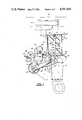
- FIG. 1 is a side elevation view in section of a primary circuit interrupter showing the lockout apparatus mounted on the arc chamber.
- FIG. 2 is a view similar to FIG. 1 showing the lockout apparatus in the lockout position.
- FIG. 3 is a view of a lockout apparatus including a magnetic release mechanism.
- FIG. 4 is a view of a lockout apparatus having a mechanical release mechanism.
- FIG. 5 is a view of the lockout apparatus having an over center toggle trip and release mechanism.
- FIG. 6. is a view similar to FIG. 5 showing the trip and release mechanism in the lockout position.
- FIG. 7 is a view of an alternate mechanical lockout apparatus.
- FIG. 8 is a view of another embodiment of the invention showing a double float trip mechanism.
- Primary circuit breakers of the type contemplated herein and as disclosed in my earlier patent and co-pending application generally include a base 10 having mounted thereon an arc extinguishing assembly 12, a latch mechanism 14, a trip lever 16, a trip assembly 18 and a manua11y actuated crank shaft assembly 19.
- a fixed contact 20 is provided in the work chamber 24 of the arc extinguishing assembly and is connected to the primary bushing of the transformer by a line 21.
- a movable rod contact 22 is positioned in the work chamber 24 and is operatively connected to the latch mechanism 14. Under fault current conditions, the rod 22 is moved away from the contact 20, producing an arc which builds up pressure in the work chamber 24. The arc is extinguished by the cross-blast of the gases built up in chamber 24 across the arc produced between the contact 20 and rod 22. These gases are discharged through the passage 26.
- the latch mechanism 14 is moved between open and closed positions by means of the manual crankshaft assembly 19 which includes an eccentric crank section 52 and a yoke 53.
- the yoke is connected to the latch mechanism 14 by means of a spring 55.
- the yoke 53 is rotated past the pivot point 57 of the latch mechanism 14 to move the rod 22 into and out of engagement with the contact 20.
- the latch mechanism 14 includes a first lever 15 connected to spring 55 and a second lever 17 connected to the contact 20.
- the trip lever 16 is tripped by the magnetic trip assembly 18 to release the rod 22 from the latch mechanism 14 to open the circuit under a fault condition.
- the fault condition is sensed by a heating element 28 provided in the trip assembly 18.
- the element 28 is connected to the power source by a line 30 and to the rod 22 by a line 32.
- the trip assembly includes a magnet 34 supported on a bell crank 36 which is biased by a spring 38 to pivot about the pivot point 40.
- the bell crank 36 includes an arm 47 which is positioned to engage the trip lever 16.
- the trip lever 16 is connected to a latch member 59 that is mounted on the first lever 15.
- the latch member 59 connects the first lever 15 to the second lever 17.
- the second lever 17 is released from the first lever 15 when the trip lever 16 is pivoted by the bell crank 36.
- the magnet 34 in the trip assembly 18 is released when the heating element 28 reaches the Curie temperature.
- the circuit breaker is shown in the closed position.
- the lockout apparatus or device includes a float 44 mounted on an insulating rod 46 which is supported in a pair of openings 48, 49 provided in the base 10 and guide plate 104, respectively.
- the float responds to the level of the oil 50 in the transformer.
- the float is shown in the elevated position and in phantom lines in the lockout position.
- the rod 46 In the solid line position, the rod 46 is located just above the crank shaft section 52 and is prevented from further upward movement by means of a pin 51 which engages guide plate 104.
- the rod 46 In the phantom line position, the rod 46 is located in the path of motion of the crank shaft section 52, preventing manual opening of the contacts.
- the circuit breaker is shown in the open position.
- the oil level 50 is shown at a predetermined level with respect to the arc interrupting assembly with the float 44 shown resting on the guide plate 104 on the upper surface of the arc extinguishing assembly 12.
- the rod 46 has moved downward into the path of motion of the crank section 52. The rod 46 will prevent rotation of the crank section 52.
- FIG. 3 a magnetic trip and lockout apparatus or device 60 is shown which is used to both trip the trip assembly 18 as well as lockout any movement of the crank arm 52.
- a soft iron member 62 is mounted on the rod 46 by means of an arm 64. As the iron member is moved toward the magnet 34, substantially all of the magnetic flux of the magnet will shunt through the soft iron member 62. This will greatly reduce the attraction of the magnet to the heating element 28. As the iron member 62 approaches the magnet 34, the attraction of the magnet to the soft iron member will increase pulling the float 60 downward in the oil. The pull up force of the float acting on the magnet will increase due to the buoyancy effect of the float in the oil.
- FIG. 4 another embodiment is shown which utilizes a mechanical trip member 61 to open the circuit.
- a cam or ramp 66 is mounted on the rod 46 and a release arm 68 having a cam follower 70 is provided on the magnet 34.
- the cam follower 70 will ride up on the cam or ramp 66, pushing the magnet 34 away from the element 28 far enough for the magnet to be released from the element and to trip the trip release 16 to open the contacts in the arc extinguishing assembly.
- the rod 46 is controlled by means of a float 72 mounted on an arm 74 that is pivotally supported on a bracket 76 by means of a pin 78.
- the rod is held in an upward position by means of a tab 80 mounted on the end of the arm 74 which is movable into a latching position in a groove 82 provided in the rod 46.
- Means are also provided for biasing the rod 46 to the lockout position.
- Such means is in the form of a spring 84 mounted on the rod 46 between the bracket 76 and a retainer ring 86 mounted on the rod.
- FIGS. 5 and 6 another form of mechanical release trip lockout apparatus 85 is shown.
- the rod 46 is connected to an arm 84 pivotally mounted on a bracket 86 by means of a pin 88.
- a float 90 is mounted on the end of an arm 92 which is pivotally mounted on a bracket 94 by means of a pin 96.
- the arm 92 is connected to the arm 84 by means of spring 98.
- the spring 98 will be moved over center far enough to snap the arm 84 downward to push the rod down.
- the cam 66 will push the cam follower 70 far enough to trip the trip assembly 18 to interrupt the circuit and rod 46 will lockout the path of motion of the crankshaft section 52.
- the trip lockout mechanism includes a weight 100 mounted on the upper end of the rod 46 with a float 102 connected to the weight 100.
- the rod 46 should be made square where it passes through the guide plate 104 so that the float 102 will not interfere with the release arm 68 on the magnet 34.
- FIG. 8 a double float trip lock automatic mechanism is shown which provides a positive force for tripping the magnet 34 away from element 28.
- the first float 44 is mounted on a rod 46 as shown in FIG. 1.
- the second float 106 is mounted on a lever arm 108 that is pivotally mounted on a support 110 by means of a pin 112.
- a weight 107 may be added to the end of arm 108, if desired.
- the operation of the interrupter is the same as described for the circuit breaker of FIG. 1.
- the first float 44 of the lockout mechanism shown in FIG. 8 will float with the oil level to move the rod 46 into the path of motion of the crank 52.
- the second float 106 will also follow the oil level pivoting the arm downward into engagement with a stop member 114 provided on the rod 46.
- the increasing weight of the float 106 and weight 107 if added, will snap the latch open if the first float 44 is not heavy enough to open the latch.
Abstract
Description
Claims (16)
Priority Applications (10)
Application Number | Priority Date | Filing Date | Title |
---|---|---|---|
US06/699,423 US4591816A (en) | 1985-02-07 | 1985-02-07 | Low oil trip and/or lockout apparatus |
AU52850/86A AU584666B2 (en) | 1985-02-07 | 1986-01-30 | Low oil trip and/or lockout apparatus |
CA000500654A CA1252176A (en) | 1985-02-07 | 1986-01-30 | Circuit breaker low oil trip and/or lockout apparatus |
AT86630019T ATE55509T1 (en) | 1985-02-07 | 1986-02-03 | RELEASE AND/OR LOCKING DEVICE RESPONDING TO OIL LEVEL BELOW. |
DE8686630019T DE3673181D1 (en) | 1985-02-07 | 1986-02-03 | RELEASE AND / OR LOCKING DEVICE REACTING ON OIL LEVEL UNDERWAY. |
EP86630019A EP0190985B1 (en) | 1985-02-07 | 1986-02-03 | Low oil trip and/or lockout apparatus |
BR8600418A BR8600418A (en) | 1985-02-07 | 1986-02-03 | DEVICE AND / OR LOW OIL BLOCKING DEVICE |
DE198686630019T DE190985T1 (en) | 1985-02-07 | 1986-02-03 | RELEASE AND / OR LOCKING DEVICE REACTING ON OIL LEVEL UNDERWAY. |
KR1019860000811A KR940000152B1 (en) | 1985-02-07 | 1986-02-06 | Low oil trip/or lockout apparatus |
JP61025664A JPS61211930A (en) | 1985-02-07 | 1986-02-07 | Low oil response lockout apparatus |
Applications Claiming Priority (1)
Application Number | Priority Date | Filing Date | Title |
---|---|---|---|
US06/699,423 US4591816A (en) | 1985-02-07 | 1985-02-07 | Low oil trip and/or lockout apparatus |
Publications (1)
Publication Number | Publication Date |
---|---|
US4591816A true US4591816A (en) | 1986-05-27 |
Family
ID=24809255
Family Applications (1)
Application Number | Title | Priority Date | Filing Date |
---|---|---|---|
US06/699,423 Expired - Fee Related US4591816A (en) | 1985-02-07 | 1985-02-07 | Low oil trip and/or lockout apparatus |
Country Status (9)
Country | Link |
---|---|
US (1) | US4591816A (en) |
EP (1) | EP0190985B1 (en) |
JP (1) | JPS61211930A (en) |
KR (1) | KR940000152B1 (en) |
AT (1) | ATE55509T1 (en) |
AU (1) | AU584666B2 (en) |
BR (1) | BR8600418A (en) |
CA (1) | CA1252176A (en) |
DE (2) | DE190985T1 (en) |
Cited By (17)
Publication number | Priority date | Publication date | Assignee | Title |
---|---|---|---|---|
US6111212A (en) * | 1998-04-21 | 2000-08-29 | Cooper Industries, Inc. | Interrupt assembly for a primary circuit breaker |
US20060017531A1 (en) * | 2004-07-21 | 2006-01-26 | Eley Edgar R | Interrupter assembly for a circuit breaker |
US20060151306A1 (en) * | 2004-12-21 | 2006-07-13 | Lau Allen K | Build-in loto device on equipment breaker panel |
US7199686B1 (en) * | 2005-10-03 | 2007-04-03 | Jaker Electric Co., Ltd. | Oil-immersed and high-pressure tripping switch structure |
US20090277768A1 (en) * | 2008-05-08 | 2009-11-12 | Cooper Technologies Company | Low Oil Trip Assembly for a Fault Interrupter and Load Break Switch |
US20090278636A1 (en) * | 2008-05-08 | 2009-11-12 | Cooper Technologies Company | Indicator for a fault interrupter and load break switch |
US20090279216A1 (en) * | 2008-05-08 | 2009-11-12 | Cooper Technologies Company | Adjustable Rating for a Fault Interrupter and Load Break Switch |
US20090278635A1 (en) * | 2008-05-08 | 2009-11-12 | Cooper Technologies Company | Fault Interrupter and Load Break Switch |
US20090279223A1 (en) * | 2008-05-08 | 2009-11-12 | Cooper Technologies Company | Sensor Element for a Fault Interrupter and Load Break Switch |
US20090278634A1 (en) * | 2008-05-08 | 2009-11-12 | Cooper Technologies Company | Multiple Arc Chamber Assemblies for a Fault Interrupter and Load Break Switch |
US20100038221A1 (en) * | 2008-08-14 | 2010-02-18 | Cooper Technologies Company | Tap Changer Switch |
US20100038222A1 (en) * | 2008-08-14 | 2010-02-18 | Cooper Technologies Company | Multi-Deck Transformer Switch |
WO2010065733A1 (en) * | 2008-12-04 | 2010-06-10 | Cooper Technologies Company | Low force low oil trip mechanism |
US7872203B2 (en) | 2008-08-14 | 2011-01-18 | Cooper Technologies Company | Dual voltage switch |
CN104134576A (en) * | 2014-07-16 | 2014-11-05 | 国家电网公司 | Three-pin reed switch type double-circuit trip node gas relay |
US20150131186A1 (en) * | 2012-07-20 | 2015-05-14 | Abb Technology Ag | Safety device for a power transformer, and related power transformer using such a safety device |
US9543094B2 (en) | 2014-05-05 | 2017-01-10 | Maine Technical Services, Inc. | Extension member for rotary switch actuation |
Families Citing this family (1)
Publication number | Priority date | Publication date | Assignee | Title |
---|---|---|---|---|
FR2942353B1 (en) * | 2009-02-19 | 2011-06-17 | Transfix Toulon Sa Soc Nouv | METHOD, DEVICE AND SYSTEM FOR PROTECTING AN ELECTRICAL APPARATUS, AND TRANSFORMER AND STATION COMPRISING SUCH A DEVICE OR SYSTEM |
Citations (1)
Publication number | Priority date | Publication date | Assignee | Title |
---|---|---|---|---|
US4435690A (en) * | 1982-04-26 | 1984-03-06 | Rte Corporation | Primary circuit breaker |
Family Cites Families (4)
Publication number | Priority date | Publication date | Assignee | Title |
---|---|---|---|---|
FR26190E (en) * | 1921-12-15 | 1923-09-05 | Metallurg Electr | High voltage switch |
US4324961A (en) * | 1976-05-18 | 1982-04-13 | Westinghouse Electric Corp. | Distribution transformer having a primary disconnect switch |
US4550298A (en) * | 1984-01-23 | 1985-10-29 | Rte Corporation | Trip assembly for a circuit breaker |
US4611189A (en) * | 1985-02-07 | 1986-09-09 | Rte Corporation | Underoil primary circuit breaker |
-
1985
- 1985-02-07 US US06/699,423 patent/US4591816A/en not_active Expired - Fee Related
-
1986
- 1986-01-30 AU AU52850/86A patent/AU584666B2/en not_active Ceased
- 1986-01-30 CA CA000500654A patent/CA1252176A/en not_active Expired
- 1986-02-03 AT AT86630019T patent/ATE55509T1/en not_active IP Right Cessation
- 1986-02-03 BR BR8600418A patent/BR8600418A/en not_active IP Right Cessation
- 1986-02-03 DE DE198686630019T patent/DE190985T1/en active Pending
- 1986-02-03 DE DE8686630019T patent/DE3673181D1/en not_active Expired - Fee Related
- 1986-02-03 EP EP86630019A patent/EP0190985B1/en not_active Expired - Lifetime
- 1986-02-06 KR KR1019860000811A patent/KR940000152B1/en not_active IP Right Cessation
- 1986-02-07 JP JP61025664A patent/JPS61211930A/en active Pending
Patent Citations (1)
Publication number | Priority date | Publication date | Assignee | Title |
---|---|---|---|---|
US4435690A (en) * | 1982-04-26 | 1984-03-06 | Rte Corporation | Primary circuit breaker |
Cited By (34)
Publication number | Priority date | Publication date | Assignee | Title |
---|---|---|---|---|
US6111212A (en) * | 1998-04-21 | 2000-08-29 | Cooper Industries, Inc. | Interrupt assembly for a primary circuit breaker |
US20060017531A1 (en) * | 2004-07-21 | 2006-01-26 | Eley Edgar R | Interrupter assembly for a circuit breaker |
US7154061B2 (en) | 2004-07-21 | 2006-12-26 | Abb Inc. | Interrupter assembly for a circuit breaker |
US20060151306A1 (en) * | 2004-12-21 | 2006-07-13 | Lau Allen K | Build-in loto device on equipment breaker panel |
US7148435B2 (en) | 2004-12-21 | 2006-12-12 | Applied Materials, Inc. | Build-in LOTO device on equipment breaker panel |
US7199686B1 (en) * | 2005-10-03 | 2007-04-03 | Jaker Electric Co., Ltd. | Oil-immersed and high-pressure tripping switch structure |
WO2009137550A1 (en) * | 2008-05-08 | 2009-11-12 | Cooper Technologies Company | Low oil trip assembly for a fault interrupter and load break switch |
US20090278636A1 (en) * | 2008-05-08 | 2009-11-12 | Cooper Technologies Company | Indicator for a fault interrupter and load break switch |
US7920037B2 (en) | 2008-05-08 | 2011-04-05 | Cooper Technologies Company | Fault interrupter and load break switch |
US20090279216A1 (en) * | 2008-05-08 | 2009-11-12 | Cooper Technologies Company | Adjustable Rating for a Fault Interrupter and Load Break Switch |
US20090278635A1 (en) * | 2008-05-08 | 2009-11-12 | Cooper Technologies Company | Fault Interrupter and Load Break Switch |
US20090279223A1 (en) * | 2008-05-08 | 2009-11-12 | Cooper Technologies Company | Sensor Element for a Fault Interrupter and Load Break Switch |
US20090278634A1 (en) * | 2008-05-08 | 2009-11-12 | Cooper Technologies Company | Multiple Arc Chamber Assemblies for a Fault Interrupter and Load Break Switch |
US20090277768A1 (en) * | 2008-05-08 | 2009-11-12 | Cooper Technologies Company | Low Oil Trip Assembly for a Fault Interrupter and Load Break Switch |
US8004377B2 (en) | 2008-05-08 | 2011-08-23 | Cooper Technologies Company | Indicator for a fault interrupter and load break switch |
US7683287B2 (en) | 2008-05-08 | 2010-03-23 | Cooper Technologies Company | Multiple arc chamber assemblies for a fault interrupter and load break switch |
US7952461B2 (en) | 2008-05-08 | 2011-05-31 | Cooper Technologies Company | Sensor element for a fault interrupter and load break switch |
US7936541B2 (en) | 2008-05-08 | 2011-05-03 | Cooper Technologies Company | Adjustable rating for a fault interrupter and load break switch |
US8013263B2 (en) | 2008-08-14 | 2011-09-06 | Cooper Technologies Company | Multi-deck transformer switch |
US20100038222A1 (en) * | 2008-08-14 | 2010-02-18 | Cooper Technologies Company | Multi-Deck Transformer Switch |
US8153916B2 (en) | 2008-08-14 | 2012-04-10 | Cooper Technologies Company | Tap changer switch |
US20100038221A1 (en) * | 2008-08-14 | 2010-02-18 | Cooper Technologies Company | Tap Changer Switch |
US7872203B2 (en) | 2008-08-14 | 2011-01-18 | Cooper Technologies Company | Dual voltage switch |
KR20110089850A (en) * | 2008-12-04 | 2011-08-09 | 쿠퍼 테크놀로지스 컴파니 | Low force low oil trip mechanism |
WO2010065733A1 (en) * | 2008-12-04 | 2010-06-10 | Cooper Technologies Company | Low force low oil trip mechanism |
US20100142102A1 (en) * | 2008-12-04 | 2010-06-10 | Cooper Technologies Company | Low Force Low Oil Trip Mechanism |
US8331066B2 (en) | 2008-12-04 | 2012-12-11 | Cooper Technologies Company | Low force low oil trip mechanism |
CN102239536B (en) * | 2008-12-04 | 2015-03-11 | 库帕技术公司 | Low force low oil trip mechanism |
AU2009322358B2 (en) * | 2008-12-04 | 2015-04-09 | Eaton Intelligent Power Limited | Low force low oil trip mechanism |
KR101588486B1 (en) | 2008-12-04 | 2016-02-12 | 쿠퍼 테크놀로지스 컴파니 | Low force low oil trip mechanism |
US20150131186A1 (en) * | 2012-07-20 | 2015-05-14 | Abb Technology Ag | Safety device for a power transformer, and related power transformer using such a safety device |
US9728357B2 (en) * | 2012-07-20 | 2017-08-08 | Abb Schweiz Ag | Safety device for a power transformer, and related power transformer using such a safety device |
US9543094B2 (en) | 2014-05-05 | 2017-01-10 | Maine Technical Services, Inc. | Extension member for rotary switch actuation |
CN104134576A (en) * | 2014-07-16 | 2014-11-05 | 国家电网公司 | Three-pin reed switch type double-circuit trip node gas relay |
Also Published As
Publication number | Publication date |
---|---|
EP0190985A3 (en) | 1987-01-07 |
CA1252176A (en) | 1989-04-04 |
ATE55509T1 (en) | 1990-08-15 |
AU5285086A (en) | 1986-08-14 |
EP0190985B1 (en) | 1990-08-08 |
KR860006820A (en) | 1986-09-15 |
DE3673181D1 (en) | 1990-09-13 |
JPS61211930A (en) | 1986-09-20 |
DE190985T1 (en) | 1987-02-05 |
AU584666B2 (en) | 1989-06-01 |
KR940000152B1 (en) | 1994-01-07 |
BR8600418A (en) | 1986-10-14 |
EP0190985A2 (en) | 1986-08-13 |
Similar Documents
Publication | Publication Date | Title |
---|---|---|
US4591816A (en) | Low oil trip and/or lockout apparatus | |
US4409573A (en) | Electromagnetically actuated anti-rebound latch | |
US4255732A (en) | Current limiting circuit breaker | |
US4679018A (en) | Circuit breaker with shock resistant latch trip mechanism | |
US2144475A (en) | Circuit breaker | |
EP0093076A2 (en) | Primary circuit breaker | |
GB1562107A (en) | Composite electricmotor controller | |
US5546062A (en) | Protection switch | |
US2320437A (en) | Circuit breaker | |
US2134572A (en) | Electric circuit breaker | |
EP0252869B1 (en) | Overload switch | |
GB2026244A (en) | Circuit breaker tripping | |
US4220935A (en) | Current limiting circuit breaker with high speed magnetic trip device | |
AU2004201318A1 (en) | Circuit breaker mechanism including mechanism for breaking tack weld | |
US4473860A (en) | Contactor apparatus comprising automatic opening means and a local control member | |
US4025886A (en) | Electric circuit breaker with electro-magnetically-assisted closing means | |
US2370024A (en) | Circuit breaker | |
US2624815A (en) | Circuit breaker | |
US2483602A (en) | Circuit breaker | |
US4554524A (en) | Secondary circuit breaker for distribution transformer with indicator light switch mechanism | |
US2078784A (en) | Electric circuit breaker | |
US3072765A (en) | Circuit breaker | |
US2701828A (en) | Electrically operated switch and sectionalizer | |
US4124833A (en) | Overcurrent protection equipment | |
US4617545A (en) | Submersible primary circuit breaker |
Legal Events
Date | Code | Title | Description |
---|---|---|---|
AS | Assignment |
Owner name: RTE CORPORATION, Free format text: ASSIGNMENT OF ASSIGNORS INTEREST.;ASSIGNORS:MIKULECKY, HARVEY W.;KNAPP, TODD K.;REEL/FRAME:004523/0058 Effective date: 19851231 |
|
AS | Assignment |
Owner name: COOPER POWER ACQUISITION COMPANY, A CORP. OF DE Free format text: MERGER;ASSIGNOR:RTE CORPORATION;REEL/FRAME:005077/0379 Effective date: 19880725 Owner name: COOPER POWER SYSTEMS, INC.,, STATELESS Free format text: CHANGE OF NAME;ASSIGNOR:COOPER POWER ACQUISTION COMPANY;REEL/FRAME:005060/0052 Effective date: 19881114 |
|
FPAY | Fee payment |
Year of fee payment: 4 |
|
REMI | Maintenance fee reminder mailed | ||
LAPS | Lapse for failure to pay maintenance fees | ||
FP | Lapsed due to failure to pay maintenance fee |
Effective date: 19940529 |
|
STCH | Information on status: patent discontinuation |
Free format text: PATENT EXPIRED DUE TO NONPAYMENT OF MAINTENANCE FEES UNDER 37 CFR 1.362 |