US4590336A - Special circuit transfer via cable analyzer - Google Patents
Special circuit transfer via cable analyzer Download PDFInfo
- Publication number
- US4590336A US4590336A US06/669,767 US66976784A US4590336A US 4590336 A US4590336 A US 4590336A US 66976784 A US66976784 A US 66976784A US 4590336 A US4590336 A US 4590336A
- Authority
- US
- United States
- Prior art keywords
- pair
- old
- tip
- master
- ring
- Prior art date
- Legal status (The legal status is an assumption and is not a legal conclusion. Google has not performed a legal analysis and makes no representation as to the accuracy of the status listed.)
- Expired - Lifetime
Links
Images


Classifications
-
- H—ELECTRICITY
- H04—ELECTRIC COMMUNICATION TECHNIQUE
- H04B—TRANSMISSION
- H04B3/00—Line transmission systems
- H04B3/02—Details
- H04B3/46—Monitoring; Testing
-
- H—ELECTRICITY
- H04—ELECTRIC COMMUNICATION TECHNIQUE
- H04M—TELEPHONIC COMMUNICATION
- H04M3/00—Automatic or semi-automatic exchanges
- H04M3/22—Arrangements for supervision, monitoring or testing
- H04M3/26—Arrangements for supervision, monitoring or testing with means for applying test signals or for measuring
- H04M3/28—Automatic routine testing ; Fault testing; Installation testing; Test methods, test equipment or test arrangements therefor
Definitions
- This invention pertains to computer design. Applicant designates a computer design as one having ordinary skill in the art. Therefore, this application is written so that a computer design would be able to make and use the invention.
- This invention is to be used with communication cables; and particularly is used to transfer special circuits for old cable to new cable.
- T-circuits The normal telephone systems and networks were originally installed for voice communication by "plain old telephones". However, they have now come to be used extensively for special circuits. Some of these special circuits are called “T-circuits”. Often, either very high frequency transmissions or high speed data is transmitted by these special circuits.
- the two wires of a pair are designated in the phone system as the ring and tip.
- One wire being the ring and one wire being the tip of each pair. It was known that various tests could be made; e.g., the voltage determined between the ring and tip, the ring and ground, and tip and ground. Also, in the absence of voltage, the resistance from ring to tip, ring to ground, and tip to ground could be determined.
- This invention uses a cable analyzer which is unique in several respects.
- TCX TCX receptacle
- the analyzer is computerized so that a series of procedures may be conducted.
- the panel has a 16 key input board. By keying two keys, a particular program may be used which, for example, would conduct a transfer.
- Two analyzers may be connected together and programmed so that one is a master analyzer and the other is slave. With this, the two analyzers could be physically remote apart, and particularly, one of the analyzers be at the master end of a section of cable and the other at the slave end of a section of cable. Then, one analyzer could put a tone on a pair of wires and a +10 volts D.C. potential on the ring and a -10 volts D.C. potential on the tip. Therefore, if the other analyzer received the tone and measured the voltage as +10 volts ring and -10 volts tip, it would be certain that the two analyzers were connected to the same pair.
- the amplitude and power could be measured on the pair at the transmitting analyzer. If the amplitude and power were the same at the other analyzer, it would be an indication that all connections between the two analyzers were good electrically.
- the tone normally used for such a test is 577 Hz. Also, it is known that this tone can be transmitted in simplex form and not interfere with the special usage of even the special circuits.
- CPU central processing unit
- PROM programmable read only memory
- RAM random access memory
- the CPU will also have a clock.
- the clock will also generate a 612 KHz signal and a 4.8 KHz signal which will be transmitted to various components of the analyzer such as a converter, where the analog to digital conversion takes place as well as other functions.
- the analyzer can make and perform numerous tasks and print out the results or the conclusion of these many tasks in written form in much shorter time than they could be performed otherwise.
- the analyzer itself is only 22" (55.88 cm) wide by 8" (20.32 cm) high and 10.5" (26.67 cm) deep.
- the entire unit weighs only 28 pounds (12.7 Kg.) including the rechargeable battery power supply.
- An object of this invention is to transfer circuits from an old wire pair to a new wire pair.
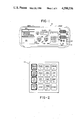
- FIG. 1 is a front elevational view of the front panel of one of the cable analyzers.
- FIG. 2 is a front elevational view of the 16 key pad.
- FIG. 3 is a schematic representation of the operation of one of the cable analyzers.
- FIG. 4 illustrates an example of the tape printed from the pretest program.
- FIG. 5 is a representation of the steps taken in a pretest program.
- FIG. 6 is a simplified schematic representation of two analyzers used for special circuit transfer.
- the analyzer will include batteries 12 which may be recharged by plug in wall transformer 14 through power supply 15.
- the analyzer will have a 25 pair plug connector which is designated as the old module or old plug connector 16. It generally bears the designation of "Cinch Jones”.
- the pins of the old connector 16 and old receptacle 20 are connected by hardwiring or old ribbon 24 to an old pair selector board 26.
- new connector 18 and new receptacle 22 are connected by a new hardwire ribbon 28 to the new pair selector board 30.
- Each pair selector board has 26 double pole relays. Both these relays, any one of the pairs in either the old connector 16 and old receptacle 20 may be connected to routing board 32.
- the connection of one of the pairs from the old connector or old receptacle to the routing board is by old buss 34, as shown.
- the connection between the relays of the new pair selector and the routing board is by the new buss 36.
- Bridge board 38 connects both to the old pair selector 26 and the new pair selector 30. It has 26 double pole-double throw relays. By the bridge board 38, any pair from the old connector 16 can be connected or bridged to the corresponding pair of the new connector 18. Also, old receptacle 20 can be connected to new receptacle 22.
- Central processing unit 40 controls the pair selection and routing, and basically all other functions of the analyzer. Besides the basic integration circuit, the CPU will include a plurality of PROM units which will contain the programs for the analyzer. It will also contain several RAM units. Also, a clock in the CPU produces 612 KHz and 4.8 KHz signals for the various components.
- the CPU 40 is connected by both data buss 42 and port buss 44 to the old pair selector 26, the new pair selector 30, the bridge board 38 and the routing board 32. It is by operation of the CPU 40 that a particular pair is selected to be connected by relay to the routing board. The CPU signals the particular test to be performed upon them. Also, it is the signal from the CPU 40 that directs the individual relays in the bridging board 38 to bridge one of the pairs from the old connector 16 to the corresponding pair on the new connector 18.
- the routing board 32 is connected by a plurality of connectors to analog to binary digital converter 46.
- the converter 46 does more than merely convert, it processes analog signal. For example, normally the first test which is made upon a pair as determined by the CPU 40 is to measure, by volt meter 43, the voltage from ring to ground, tip to ground, and ring to tip. Therefore, after the CPU has directed the converter 46 to make the voltage readings, these voltage readings are converted and are stored in the RAMS of the CPU 40. Then the voltages are analyzed by the CPU and compared to certain standards as contained in the PROMS.
- ohmmeter 45 of the converter 46 would, upon proper command or direction from the CPU 40, determine the resistance of a designated pair between ring and ground, tip and ground, and ring to tip, convert this information to binary digital code to be transmitted to the CPU for storage and analysis.
- capacitance meter 47 would make capacitance tests, ring to ground, tip to ground, and ring to tip, to be converted to binary digital code, analyzed and stored.
- the routing board 32 does more than merely route a pair (for example, pair number 7 as it might be designated inasmuch as the pairs in each group are designated from pair 1 through pair 25, ordinarily).
- the routing board besides picking out one particular pair, would also route it to the particular meter, either the ohmmeter 45, volt meter 43, or capacitance meter 47 as directed. Also, it would indicate in its routing whether the measurement was to be ring to tip, ring to ground, or tip to ground.
- the main input by the operator to the CPU 40 is by sixteen membrane key pad 48.
- the key pad is connected to display driver 50, and from there, by 40 pin ribbon 52 to front panel control 54.
- the front panel control is connected by the data buss 42 and port buss 44 to the CPU.
- Front panel control 54 is also connected to the CPU by a plurality of hard wires for standby power and reset and low battery.
- any pair on the old connector 16 or receptacle 20 or any pair on the new connector 18 or receptacle 22 may be manually selected for tests.
- a reset membrane switch 60 which is connected through the display driver 50 and front panel control 54 and hardwire 55 to the CPU 40.
- the display driver 50 is also connected to visual display board 62 which is in the form of a dual or two panel eight character liquid crystal display alphameric.
- Thermal printer 64 is connected directly to the CPU 40 and also to generator 66.
- the generator has the capabilities of generating dual tone multiple frequency (called DTMF dial tones herein).
- a 577 Hz the tone, as generated in the converter circuit 46 can be sent in a simplex mode so it is inaudible to someone using a telephone upon the line, but still can be distinguished by probe plugged in probe receptacle 68.
- the 577 Hz simplex also does not interfere with special circuit transmissions.
- Probe receptacle 68 is connected to amplifier circuit or fast switch circuit 70 which is also connected to the generator 66.
- the fast switch circuit 70 also has switching capabilities and is connected to the old receptacle 20 and the new receptacle 22.
- Ground lug 49 is connected directly to routing board 32.
- On/off switch 74 is combined with volume control 76.
- Volume control 76 is connected to the generator 66.
- the on/off switch 74 is connected to the power supply and charger 15 which interconnects the battery pack 12 and the wall transformer 14.
- the wall transformer 14 for the batteries 12 is connected to the battery charge receptacle 84.
- the power supply 15 is connected to the different elements of the analyzer 10 requiring power.
- Talk lugs 80 upon the front panel, are connected to the generator 66.
- Cord storage pocket 86 is within the front panel of the analyzer 10.
- TCX receptacle 88 on the front panel is connected to the fast switch circuit 70.
- the pretest is to obtain information about the D.C. voltage, resistance and capacities of the wires and pairs within a 25 pair group in the cable.
- the pretest is useful prior to a cable transfer so that working, faulty, or vacant pairs are readily identified.
- the CPU would cause to be displayed upon the old portion of the visual display board 62 "CABLE 00".
- the operator could key the numbers "03" indicating that the test was being made on cable 03.
- the CPU would store this information on one of the RAMS.
- the operator would press "START”.
- the new display of the visual display board 62 would read "CABLE 00".
- the operator would enter the count, e.g., "01”.
- the operator would then press "START” again.
- the new display would read "CNT 0000” since there was no new cable plugged into the new pair selector board 30, the operator would press "START” again.
- the CPU would direct the old pair selection board 26 to connect the first pair as identified on the "Cinch Jones" connector 16 to the routing board 32.
- the CPU 40 would direct the routing board to connect the ring and ground to the volt meter 43.
- the CPU would direct the converter 46 to make multiple instantaneous readings (step 100) of the voltage from ring to ground and take the average of these voltages.
- the reading from the volt meter 43 would first be an analog signal related to a selected pair.
- the analog signal will be converted to a binary digital signal for use by the CPU.
- the CPU would determine if the voltage were zero.
- step 102 the voltage of the ring to ground and proceed to the next pair. Anytime the result is printed by the printer, then the test would proceed to the next pair.
- the CPU 40 would instruct the routing board 32 to connect the tip and ground to the volt meter 43, and the converter 46 to check the voltage tip to ground (step 104). There would be multiple voltage tests and the average taken by the CPU 40. The CPU would determine if the voltage were in "busy POTS" parameter. If the voltage between tip to ground were in the busy POTS parameters (that is about -14 volts) it would then identify the pair as a busy POTS, print the pair number on the tape with the identification of "busy POTS" and proceed to the next pair (step 106). The CPU would determine if the voltage were zero. If the voltage, tip to ground, were not zero, this voltage would be printed (step 108).
- the CPU would instruct the converter to measure the resistance between tip and ground (step 110). The CPU would determine if the resistance was greater than 2.5K ohms. If the resistance were in the parameters of an idle POTS, i.e., less than about 2,500 ohms, the CPU would identify the pair as an idle POTS and cause the printer to print the line number and "POTS" and then proceed to the next pair (step 112).
- the CPU would command the routing board to again check the voltage ring to ground (step 114). Then, this voltage would be printed (step 116) and the CPU would go on to the next pair.
- the CPU 40 would instruct the routing board 32 to connect tip and ground to the converter 46 and voltage would be checked between tip and ground (step 118). If the voltage between tip and ground were not zero, this voltage would be printed (step 120).
- the resistance would be measured between ring to ground (step 122).
- the reading of the ohmmeter 45 will be an analog signal related to a selected pair.
- the analog signal will be converted to a binary digital signal for use by the CPU. If this resistance were below about 450K ohms, the resistance value would be printed (step 124) and the CPU would go onto the next pair.
- the CPU 40 would direct the routing board 32 to connect the tip and ground to the ohmmeter 45 and the ohmmeter to measure the resistance of the tip to ground (step 126). Again, if it were below about 450K ohm, the value would be printed (step 128).
- the CPU would direct the board to connect the ring and tip to the ohmmeter 45 and the resistance read (step 130). If there were resistance to ring and tip below about 450K ohm, this value would be printed on the tape and the CPU would go onto the next pair (step 132).
- the CPU would direct that the ring and ground be connected to the capacitance meter 47, and the converter 46 to conduct a capacitance test (step 134).
- the reading from the capacitance meter 47 will be an analog signal related to a selected pair.
- the analog signal will be converted to a binary digital signal for use by the CPU.
- This capacitance would be stored in memory, and then the CPU would direct the routing board to connect the tip and ground to the capacitance meter.
- the CPU would direct the converter to determine the capacity tip to ground (step 136), and then this value would be compared at the CPU 40 to the value of the capacitance ring to ground. If they were not about the same value (the difference less than about 5%), the percent of unbalance between these capacitance values would be printed on the tape, and the CPU would go to the next pair (step 138).
- the CPU would direct the routing board to connect the ring and tip to the capacitance meter 47, and the capacitance determined between ring and tip (step 140). This value would be converted at the CPU into an equivalency of thousands of feet and this value printed on the tape, and the CPU would go to the next pair (step 142).
- pair 1 shows that there was -50 volts between ring and ground. However, the assumption is that the tip parameters were not that of POTS. The -50 volts ring to ground indicates certain special circuits.
- Pair 2 6, 7, 13, 19, and 20 shows POTS.
- Pair 4 shows a busy POTS.
- Pair 3 and several of the others show a length in 1,000 feet (KF.) between the ring and tip (RT.). Therefore, the analyzer shows that the length of the pair 3 line is 1,750 feet. Also, this means that there are no voltages and all resistances are greater than 450,000 ohms.
- Pair 12, 17, and 24 indicate open line. This means there are no voltages and all resistances are greater than 450,000 ohms. This means that the capacitance meter indicated the length of the line was very short, meaning that probably the pair open within a few feet of the test set.
- Pair 16 and 18 show a rather low voltage ring to ground. This probably indicates some special circuits such as an alarm system upon the line.
- Pair 21, 22, and 25 show an unbalance of 11%, 64%, and 11% respectively. This indicates that the line is vacant, no voltage, high resistance, but with some problem on the line to cause the capacitance of the ring and tip to be different or that there is possibly a special circuit with no battery on the pair.
- results could be transmitted to a remote location.
- the analyzer could be controlled by a remote location.
- the example of the measuring the voltage would be as indicated above that there would be a repeated measurement of the instantaneous voltage by the volt meter 43 in the converter 46. Then each of the values would be converted to binary digital form to be put to the CPU where the several values would be stored in memory. Then, upon the completion of the multiple tests, they would be averaged. Likewise, multiple resistance readings would be taken, converted to binary digital mode, sent to the CPU, stored in memory, then called up to be averaged and used. The same is also true for the capacitance test. Multiple instantaneous readings are made, converted, stored, and averaged.
- Old pair 200 with a certain old section 202 are in an old cable. According to this example, this transfer is being made so that new section 204 of new pair of wires 206 in a new cable may be put into service and the old section 202 be taken out of service.
- old and new are being used herein, not to indicate age. By “old”, it is meant that this pair of wires or cable is being removed from service, and by “new”, it is meant that this pair of wires, not previously in service, is being placed in service.
- the area wherein the one end of the new pair ends will be referred to as the master end 208.
- Master analyzer 10M will be located at this area which will be adjacent to the old pair 200 at this area.
- slave end 210 the other end of the new pair 206 will be designated as slave end 210, which will likewise be adjacent to the old pair 200.
- the slave analyzer 10S will be located at this area.
- the fast switch circuit 70 will include double pole-double throw relay 212.
- One pair of the poles will be identified as old poles 214, inasmuch as they are connected in the analyzer to old receptacle 20, which is marked with black for identification.
- the other pair of poles of the double pole-double throw relay 212 will be designated as new poles 216, inasmuch as they are connected by internal wiring to the new receptacle 22 marked white for identification.
- Reed contacts 218 of the relay 212 are connected to the TCX or reed receptacle 88.
- FIG. 6, for conciseness and clarity, does not show the entire analyzer.
- Each of the analyzers will be the same as that shown in FIG. 3, but certain elements have been omitted inasmuch as they have already been explained or they are not necessarily used in the special circuit transfer. Even if they are used, their use and operation is so obvious, that it was felt that there would be greater clarity to simplify the graphic representation.
- the selector boards 26 and 30 have not been shown, since for the entire program, the old receptacle 20 is connected to the routing board 32 as is the new receptacle 22. Therefore, for clarity and simplicity, these were shown as a direct connection from the receptacles 20 and 22 to the routing board 32.
- the meters and converter board 46 are shown as before.
- the CPU 40 which is connected by the data and port buss 42 to the fast switch circuit 70, the routing board 32, and the meter and converter board 46.
- the master analyzer 10M will be physically at a considerable distance from the slave analyzer 10S. So that the two analyzers can function in many regards as a single unit, they are connected by data link 226.
- This data link is provided by connecting the data portion of the talk and data receptacle 82 to an otherwise vacant pair of wires which extends within the new cable through the new section 204. Although the connection may not be direct, the data link 226 connects the two CPUs together so that particularly, the directions from the master CPU 40 can be transmitted to the slave CPU.
- a splicer will be at each end, which for convenience will be referred to as the master splicer and the slave splicer.
- a talk circuit is established between them, this by connecting the talk clips to an otherwise vacant pair of wires from the talk half of the receptacle 82.
- both of the analyzers be well grounded or bonded to the sheath of the cable, as before, by ground lug 72.
- old or black cord 220 is connected to the old pair 200 on both the master and slave end.
- the black cord 220 is inserted into the old receptacle 20.
- new or white cord 222 will be plugged into the new receptacle 22, and both the cord and the receptacle will be marked white for identification. It is imperative that all of the connection be made so that the ring and tip are always identified and correctly oriented.
- the ring wire or connections are identified by a small circle and the tip wire or connections are identified by a dot.
- the reed cord 224 from receptacle 88 is connected to the old pair 200 outboard of the connection 220.
- the term outboard is used to indicate that it is further from the section 202, which is to be removed from the old cable. It is necessary that the distance between the inboard connection of old cord 220 and the reed cord 224 be sufficient so that there is sufficient wire to splice the old wires still connected to the reed cord 224 to the new pair 206.
- the connection of the reed cord 224 is made by both the master and the slave. Then, with the reed still connecting to the old, then new cord 222 is attached to the new pair 206.
- the old wire pair is cut between the cords 220 and 224.
- the cut is made adjacent to old cord 220.
- the transfer is made by the master analyzer 10M.
- the master CPU 40 gives the command or direction for both the relay 212 in the master analyzer 10M and the relay 212 in the slave analyzer 10S to move from the old poles 214 to the new poles 216. This movement will be very fast, taking less than 1 millisecond. Also, it will be simultaneously, or nearly so.
- the old pair as connected to reed cord 224 would be spliced to the new pair 208 at the master end, and also the old pair at the reed cord 224 would be spliced to the new pair 206 at the slave end 210.
- the analyzer circuits previously described inasmuch as the old receptacle 20 is connected to the sleeve routing circuit 32 which has available, all of the identifying tones and voltages. Then, the master, looking at its old receptacle 20, can see if it receives the same +10 volts, -10 volts, and simplex 577 Hz tone. The amplitude of the tone at the slave can be measured and the amplitude of the tone of the master can be measured, and the comparison of these measurements be made by the master CPU. If the match is made, then it would be assured that the pair 200 in section 202 had been taken out of the old cable and that the cord 220, master and slave, were connected to the same pair.
- the master CPU immediately commands the voltages and tones be disconnected and both the relays 212, master and slave, to reconnect the circuit to the old pair 200.
- both the master and the slave analyzers are grounded by the ground lug 72 to the cable sheath.
- the data cords, master and slave are connected to an otherwise vacant pair of wires 226 in the new cable through section 204.
- the talk cords are connected, master and slave, to an otherwise vacant pair in section 204 of the new cable.
- the slave splicer keys in ID, 2, START, upon the slave analyzers key pad 48.
- the master splicer will key in ID, 2, AUTO, on the master key pad 48.
- the keying of START on the slave and AUTO on the master establishes which of the analyzers is master and which is the slave.
- the master analyzer After the analyzers are turned on, and after the data link has been confirmed as correctly connected, the master analyzer will display "WANT TO IDENTIFY", and the slave analyzer will display "PLEASE STAND BY". The master splicer will press the "START” key to proceed to identify. Then, according to the program brought up by the ID, 2, AUTO, the master analyzer will display, "CONN BLK TO NEW", meaning black cord to new, while the slave analyzer will still say "PLEASE STAND BY”. The master splicer will connect the black cord 220 extending from old receptacle 20 to the new pair 206. Upon completion of that, he will press the "START" key.
- the master CPU will turn on a tone upon the master set which is applied through the routing circuit to the old receptacle 20, and thus to the old pair of the cable to which the cord is applied. It will also activate the probe in the in the receptacle 68 at the slave and display "IDENTIFY NEW" on both the master and slave analyzer.
- the slave splicer will use the probe to identify the new pair and press “START”.
- the master splicer will also press the "START" key, and both the master and slave analyzer will display "PLEASE STAND BY”.
- the CPU will direct that the tone be turned off at the master and the probe be deactivated at the slave.
- the master analyzer will display "CONN BLK TO OLD" while the slave analyzer continues to display "PLEASE STAND BY".
- the master splicer will then take the black cord 220, still connected to the old receptacle 20 connect it to the old pair 200. Upon completion of that task, he will press the "START" key. This will cause the CPU to activate the tone upon the master set to the cord 220 and to activate the probe receptacle 68 at the slave. Also, it will cause both the master and slave analyzer to display "IDENTIFY OLD". The splicer will then use the probe to identify the old pair. As discussed above, this is not a fool proof identification, but the pair that will be identified by the slave will be the one which the slave splicer believes to be the pair to which the master splicer has attached the black cord onto.
- both the splicer and slave analyzer Upon the completion of the task, and when both the slave splicer and master splicer have pressed the "START" key, both the splicer and slave analyzer will display "PLEASE STAND BY” and the program will cause the tone to be turned off at the master and the probe to be deactivated at the slave. Then, both analyzers will automatically display "CONN TCX AND OLD" which means "connect the TCX cord and the old cord”.
- both the master and the slave splicer connects the old cord 220 to the old pair inboard of the cut area. I.e., adjacent to the section 202 which is to be removed. They also connect the TCX cord 224 to the old the old pair, outboard of the connection of the old cord 220. In connection of these two cords, it is extremely important that the cords be connected ring to ring, and tip to tip.
- both analyzers will display "PLEASE STAND BY". A check of voltage, resistance, and capacitance is made for ring and tip to ground and between ring and tip to ensure no wire is connected to the new.
- the analyzer will cause the reeds of the relay to move to the new poles 216, thereby connecting the TCX cord to the new receptacle 22.
- the routing board upon direction of the CPU according to the program, will check the resistance at the master of ring to ring between the old and new receptacle, and tip to tip between the old and new receptacle. This will be the resistance from TCX receptacle 88 through the cords 224, to the ring connection, along the ring wire 200 and through the connection and cord 220 to its connection to the old receptacle 20. Therefore, if the connections are good electrical connections, the resistance will read a dead short or zero (0) resistance.
- the tip to tip should read a zero resistance, and therefore, a check to see if an error in the connection has been made. If the master analyzer checks correctly, the program, as on the PROMS in the CPU will cause the slave analyzers to make the same check.
- both analyzers will display "MASTER CORD ERR", meaning that there has been an error in the master cord.
- the master splicer will recheck and reconnect his cords, and the resistance will be checked again. If the resistance checks good, the CPU will proceed to run the program. If it does not check good, it will repeat the display of "MASTER CORD ERR" for a recheck. The same procedure is done for the slave cords.
- the analyzer will cause a tone to be placed upon the old wire by the slave and to be received by the old wire at the master.
- the amplitude is measured at the slave and at the master, and if these amplitudes correspond and match, then the analyzer goes forward. If they do not match, both analyzers display the message "OLD BUZZ ERR".
- both the master splicer and the slave splicer verify that they are attached to what has previously been identified as an old pair and correct their connections. If the buzz does not check correctly, this "OLD BUZZ ERR" will continue to be displayed until it is checked correct, and the analyzer will not permit proceeding until the tone amplitudes match as the master and slave analyzer.
- both the master splicer and the slave splicer connect the new cord or white cord 222 to the new pair 206.
- both analyzers display "PLEASE STAND BY”.
- the slave analyzer is commanded to place a tone between ring and tip on the new receptacle 22 into which the new or white cord 222 is connected.
- a +10 D.C. voltage is place ring to ground and a -10 D.C. voltage potential is placed tip to ground.
- each splicer cuts the old as described above and presses the "START” key.
- each analyzer displays "PLEASE STAND BY”, and both relays are moved with the relays from old to new.
- the check is made of the old section 206 as described in detail above. If the old section 206 does not check good as described above, each display displays "RESTORE LOOP ERR".
- old pair 200 is respliced, master and slave, and the cords removed, returning the cables to their original condition and the master and slave splicers start again from the first, i.e., at "WANT TO IDENTIFY”. If the old pair buzz does check satisfactorily, then the analyzer displays "SPLICE NEW". At this time, both the master and slave splicer splice the new to the old as discussed above and press "START".
- each analyzer displays "REMOVE OLD ONLY". Both the master and slave splicer remove the old cord 220 from the old pair 200 and press “START”. At this time, each analyzer displays "PLEASE STAND BY” and the CPU causes a check at the master analyzer by capacitance, for the amount of wire connected to old receptacle 20. If it shows anything but a very short piece (the cord 220 itself) an indication of "BLK:ERROR MASTER" is displayed on both screens. The master splicer would correct the error and press "START" whereon the program would proceed so that the slave analyzer would check for wire on the old. This test would be the same as was conducted for the master with the same corrective measures, except the display would read "BLK:ERROR SLAVE".
- the master splicer would resplice the splice he had previously made and press "START", and again, the test would be made to determine that there was a good, sound electrical splice with a dead short between the measurement points. After this is done, the CPU would cause the program to advance so that the same splice test was made on the slave unit. This test would be the same as was conducted at the master unit with an error being displayed as "SLAVE SPLICE ERR".
- the splice test interrupts the circuit no longer than the old section 202 test described above, i.e., less than 500 milliseconds.
- each analyzer displays "REMOVE CORDS”.
- Each splicer will remove the cords and press “START”.
- the slave unit Upon pressing "START”, this time the slave unit will display "PLEASE STAND BY”, and the master unit will display "SEL START OR STOP". This means to select either start or stop.
- the program will return to display "WANT TO IDENTIFY” on the master unit while still displaying "PLEASE STAND BY” on the slave. I.e., the entire sequence will begin again for the transfer of another pair.
- each analyzer will display "COMPUTER STOP". After this display, both master splicer and slave splicer, may turn the analyzers 10M and 10S off by the on/off switch 74, pack up, and go home.
- Applicant recognizes that certain program steps have not been included. E.g., Applicant has not described the resetting or erasing of entries into the RAMS at the point they are no longer needed.
- CPU Central Processing Unit
Landscapes
- Engineering & Computer Science (AREA)
- Signal Processing (AREA)
- Computer Networks & Wireless Communication (AREA)
- Testing Of Short-Circuits, Discontinuities, Leakage, Or Incorrect Line Connections (AREA)
Abstract
Description
Claims (10)
Priority Applications (1)
| Application Number | Priority Date | Filing Date | Title |
|---|---|---|---|
| US06/669,767 US4590336A (en) | 1984-11-08 | 1984-11-08 | Special circuit transfer via cable analyzer |
Applications Claiming Priority (1)
| Application Number | Priority Date | Filing Date | Title |
|---|---|---|---|
| US06/669,767 US4590336A (en) | 1984-11-08 | 1984-11-08 | Special circuit transfer via cable analyzer |
Publications (1)
| Publication Number | Publication Date |
|---|---|
| US4590336A true US4590336A (en) | 1986-05-20 |
Family
ID=24687647
Family Applications (1)
| Application Number | Title | Priority Date | Filing Date |
|---|---|---|---|
| US06/669,767 Expired - Lifetime US4590336A (en) | 1984-11-08 | 1984-11-08 | Special circuit transfer via cable analyzer |
Country Status (1)
| Country | Link |
|---|---|
| US (1) | US4590336A (en) |
Cited By (6)
| Publication number | Priority date | Publication date | Assignee | Title |
|---|---|---|---|---|
| US5021968A (en) * | 1987-01-13 | 1991-06-04 | Robertson-Ceco Corporation | Graphics-based wire-cable management system |
| US5365578A (en) * | 1992-10-15 | 1994-11-15 | Industrial Technology | Method and system for transferring special circuit telephone pairs |
| US5528662A (en) * | 1992-09-18 | 1996-06-18 | Communications Technology Corporation | Active strapping and switching device for telephone line testing |
| NL1001293C2 (en) * | 1995-09-26 | 1997-03-28 | Nederland Ptt | Method and means for replacing an electrically conductive cable with another electrically conductive cable. |
| US6201853B1 (en) | 1999-07-13 | 2001-03-13 | Communications Manufacturing Company | Telephone technician's remote assist apparatus and method |
| WO2021062490A1 (en) * | 2019-10-02 | 2021-04-08 | nbn co limited | Devices and methods for testing a data line or forming a data connection |
Citations (1)
| Publication number | Priority date | Publication date | Assignee | Title |
|---|---|---|---|---|
| US3975600A (en) * | 1975-06-06 | 1976-08-17 | Marston Harvey J | Telephone line splicing apparatus |
-
1984
- 1984-11-08 US US06/669,767 patent/US4590336A/en not_active Expired - Lifetime
Patent Citations (1)
| Publication number | Priority date | Publication date | Assignee | Title |
|---|---|---|---|---|
| US3975600A (en) * | 1975-06-06 | 1976-08-17 | Marston Harvey J | Telephone line splicing apparatus |
Cited By (9)
| Publication number | Priority date | Publication date | Assignee | Title |
|---|---|---|---|---|
| US5021968A (en) * | 1987-01-13 | 1991-06-04 | Robertson-Ceco Corporation | Graphics-based wire-cable management system |
| US5528662A (en) * | 1992-09-18 | 1996-06-18 | Communications Technology Corporation | Active strapping and switching device for telephone line testing |
| US5365578A (en) * | 1992-10-15 | 1994-11-15 | Industrial Technology | Method and system for transferring special circuit telephone pairs |
| NL1001293C2 (en) * | 1995-09-26 | 1997-03-28 | Nederland Ptt | Method and means for replacing an electrically conductive cable with another electrically conductive cable. |
| EP0766440A1 (en) * | 1995-09-26 | 1997-04-02 | Koninklijke KPN N.V. | Method and means for replacing an electrically conducting cable by another electrically conducting cable |
| US5815918A (en) * | 1995-09-26 | 1998-10-06 | Koninklijke Ptt Nederland N.V. | Method for replacing an electrically conducting cable by another electrically conducting cable |
| US6060972A (en) * | 1995-09-26 | 2000-05-09 | Koninklijke Kpn N.V. | Method and means for replacing an electrically conducting cable by another electrically conducting cable |
| US6201853B1 (en) | 1999-07-13 | 2001-03-13 | Communications Manufacturing Company | Telephone technician's remote assist apparatus and method |
| WO2021062490A1 (en) * | 2019-10-02 | 2021-04-08 | nbn co limited | Devices and methods for testing a data line or forming a data connection |
Similar Documents
| Publication | Publication Date | Title |
|---|---|---|
| JP2648406B2 (en) | Digital loop transmission system equipment | |
| US5005197A (en) | Method and apparatus as for testing a telephone line interface card | |
| EP0374224B1 (en) | Portable identifier apparatus for communication cables | |
| US6777952B2 (en) | Method and apparatus for testing cables | |
| US4277740A (en) | Cable tester for multipair cables | |
| US4186283A (en) | Test set | |
| US4257002A (en) | Automatic harness tester | |
| US4991196A (en) | Testing communications systems | |
| US4424421A (en) | Apparatus for testing subscriber carrier systems | |
| US5210703A (en) | Apparatus and methods for testing optical communications networks | |
| US4590336A (en) | Special circuit transfer via cable analyzer | |
| US3644687A (en) | Conductor identification in multiconductor means | |
| EP1825660B1 (en) | Method and system for distance measurements | |
| US4611099A (en) | Cable analyzer with D. C. functions | |
| US4609789A (en) | Verification via cable analyzer | |
| USRE33281E (en) | Cable analyzer with d.c. functions | |
| USRE31728E (en) | Test set | |
| US4933962A (en) | Continuity test set with voice communication | |
| JPH10153524A (en) | Method and apparatus for testing connection of optical fiber cables | |
| WO1988003653A1 (en) | Wire tester | |
| US5757527A (en) | Optical fiber transmission system mapping arrangement | |
| CN112887489B (en) | Multifunctional telephone network testing device and testing method using the same | |
| JP2573628Y2 (en) | Optical fiber connection status test equipment by connecting an empty line | |
| KR920000080B1 (en) | Portable line tester | |
| US4570037A (en) | Fault detection in a telephone cable pressure monitoring system |
Legal Events
| Date | Code | Title | Description |
|---|---|---|---|
| AS | Assignment |
Owner name: INDUSTRIAL INNOVATIONS, INC. HWY. 84 & JUANITA, DE Free format text: ASSIGNMENT OF ASSIGNORS INTEREST.;ASSIGNORS:RAY, JIMMY C.;MATHEWS, HELMUT W.;REEL/FRAME:004367/0457 Effective date: 19850218 |
|
| STCF | Information on status: patent grant |
Free format text: PATENTED CASE |
|
| AS | Assignment |
Owner name: COMMUNICATIONS TECHNOLOGY CORPORATION, 2237 COLBY Free format text: ASSIGNMENT OF ASSIGNORS INTEREST.;ASSIGNOR:INDUSTRIAL INNOVATION, INC., A CORP OF TX;REEL/FRAME:004539/0479 Effective date: 19860424 |
|
| FEPP | Fee payment procedure |
Free format text: PAYOR NUMBER ASSIGNED (ORIGINAL EVENT CODE: ASPN); ENTITY STATUS OF PATENT OWNER: LARGE ENTITY |
|
| FPAY | Fee payment |
Year of fee payment: 4 |
|
| FEPP | Fee payment procedure |
Free format text: PAYOR NUMBER ASSIGNED (ORIGINAL EVENT CODE: ASPN); ENTITY STATUS OF PATENT OWNER: LARGE ENTITY Free format text: PAYER NUMBER DE-ASSIGNED (ORIGINAL EVENT CODE: RMPN); ENTITY STATUS OF PATENT OWNER: LARGE ENTITY |
|
| FEPP | Fee payment procedure |
Free format text: PAT HLDR NO LONGER CLAIMS SMALL ENT STAT AS INDIV INVENTOR (ORIGINAL EVENT CODE: LSM1); ENTITY STATUS OF PATENT OWNER: LARGE ENTITY |
|
| REMI | Maintenance fee reminder mailed | ||
| REMI | Maintenance fee reminder mailed | ||
| FPAY | Fee payment |
Year of fee payment: 8 |
|
| SULP | Surcharge for late payment | ||
| FPAY | Fee payment |
Year of fee payment: 12 |