US4589340A - Sensor carrier - Google Patents
Sensor carrier Download PDFInfo
- Publication number
- US4589340A US4589340A US06/573,343 US57334384A US4589340A US 4589340 A US4589340 A US 4589340A US 57334384 A US57334384 A US 57334384A US 4589340 A US4589340 A US 4589340A
- Authority
- US
- United States
- Prior art keywords
- sensor
- housing
- mounting means
- carrier
- steel cable
- Prior art date
- Legal status (The legal status is an assumption and is not a legal conclusion. Google has not performed a legal analysis and makes no representation as to the accuracy of the status listed.)
- Expired - Fee Related
Links
- 229910000831 Steel Inorganic materials 0.000 claims abstract description 13
- 239000010959 steel Substances 0.000 claims abstract description 13
- 239000011049 pearl Substances 0.000 claims 2
- 238000004806 packaging method and process Methods 0.000 description 5
- 238000010304 firing Methods 0.000 description 3
- 238000000034 method Methods 0.000 description 3
- 244000025254 Cannabis sativa Species 0.000 description 2
- 230000005540 biological transmission Effects 0.000 description 2
- 239000011435 rock Substances 0.000 description 2
- 230000002349 favourable effect Effects 0.000 description 1
- 230000003116 impacting effect Effects 0.000 description 1
- 239000000463 material Substances 0.000 description 1
- 239000002184 metal Substances 0.000 description 1
- 230000035939 shock Effects 0.000 description 1
Images
Classifications
-
- G—PHYSICS
- G01—MEASURING; TESTING
- G01B—MEASURING LENGTH, THICKNESS OR SIMILAR LINEAR DIMENSIONS; MEASURING ANGLES; MEASURING AREAS; MEASURING IRREGULARITIES OF SURFACES OR CONTOURS
- G01B5/00—Measuring arrangements characterised by the use of mechanical techniques
- G01B5/0002—Arrangements for supporting, fixing or guiding the measuring instrument or the object to be measured
- G01B5/0004—Supports
-
- F—MECHANICAL ENGINEERING; LIGHTING; HEATING; WEAPONS; BLASTING
- F16—ENGINEERING ELEMENTS AND UNITS; GENERAL MEASURES FOR PRODUCING AND MAINTAINING EFFECTIVE FUNCTIONING OF MACHINES OR INSTALLATIONS; THERMAL INSULATION IN GENERAL
- F16M—FRAMES, CASINGS OR BEDS OF ENGINES, MACHINES OR APPARATUS, NOT SPECIFIC TO ENGINES, MACHINES OR APPARATUS PROVIDED FOR ELSEWHERE; STANDS; SUPPORTS
- F16M11/00—Stands or trestles as supports for apparatus or articles placed thereon ; Stands for scientific apparatus such as gravitational force meters
- F16M11/02—Heads
- F16M11/04—Means for attachment of apparatus; Means allowing adjustment of the apparatus relatively to the stand
- F16M11/043—Allowing translations
- F16M11/046—Allowing translations adapted to upward-downward translation movement
-
- F—MECHANICAL ENGINEERING; LIGHTING; HEATING; WEAPONS; BLASTING
- F16—ENGINEERING ELEMENTS AND UNITS; GENERAL MEASURES FOR PRODUCING AND MAINTAINING EFFECTIVE FUNCTIONING OF MACHINES OR INSTALLATIONS; THERMAL INSULATION IN GENERAL
- F16M—FRAMES, CASINGS OR BEDS OF ENGINES, MACHINES OR APPARATUS, NOT SPECIFIC TO ENGINES, MACHINES OR APPARATUS PROVIDED FOR ELSEWHERE; STANDS; SUPPORTS
- F16M11/00—Stands or trestles as supports for apparatus or articles placed thereon ; Stands for scientific apparatus such as gravitational force meters
- F16M11/20—Undercarriages with or without wheels
- F16M11/24—Undercarriages with or without wheels changeable in height or length of legs, also for transport only, e.g. by means of tubes screwed into each other
- F16M11/40—Undercarriages with or without wheels changeable in height or length of legs, also for transport only, e.g. by means of tubes screwed into each other by means of coilable or bendable legs or spiral shaped legs
-
- F—MECHANICAL ENGINEERING; LIGHTING; HEATING; WEAPONS; BLASTING
- F16—ENGINEERING ELEMENTS AND UNITS; GENERAL MEASURES FOR PRODUCING AND MAINTAINING EFFECTIVE FUNCTIONING OF MACHINES OR INSTALLATIONS; THERMAL INSULATION IN GENERAL
- F16M—FRAMES, CASINGS OR BEDS OF ENGINES, MACHINES OR APPARATUS, NOT SPECIFIC TO ENGINES, MACHINES OR APPARATUS PROVIDED FOR ELSEWHERE; STANDS; SUPPORTS
- F16M13/00—Other supports for positioning apparatus or articles; Means for steadying hand-held apparatus or articles
- F16M13/005—Other supports for positioning apparatus or articles; Means for steadying hand-held apparatus or articles integral with the apparatus or articles to be supported
-
- F—MECHANICAL ENGINEERING; LIGHTING; HEATING; WEAPONS; BLASTING
- F16—ENGINEERING ELEMENTS AND UNITS; GENERAL MEASURES FOR PRODUCING AND MAINTAINING EFFECTIVE FUNCTIONING OF MACHINES OR INSTALLATIONS; THERMAL INSULATION IN GENERAL
- F16M—FRAMES, CASINGS OR BEDS OF ENGINES, MACHINES OR APPARATUS, NOT SPECIFIC TO ENGINES, MACHINES OR APPARATUS PROVIDED FOR ELSEWHERE; STANDS; SUPPORTS
- F16M2200/00—Details of stands or supports
- F16M2200/04—Balancing means
- F16M2200/047—Balancing means for balancing translational movement of the head
Definitions
- the invention relates to a sensor carrier for military applications.
- One possible way to transport such a sensor is by using a useful load carrying projectile which is fired from a gun barrel weapon or transported by means of a rocket motor and which distributes a plurality of sensors over a target region by dropping them, for example, by parachute on the target region.
- the sensors and the electronic components which are connected to the sensors, which components process the parameters which have been received by the sensors and which transmit these parameters as radio signals, must withstand by means of a compact housing the strong shock loads which occur during firing and impacting. Such housing must carefully protect the sensor and its electronic components. For purposes of transporting a plurality of sensors in a single useful load projectile these packaged units must be compactly constructed. On the other hand the requirement exists that the sensors, for the purpose of enlarging their sensing range, are positioned after being set down on the ground as high as possible over the ground surface, so that their functioning is not inhibited by obstacles, such as, for example, rocks, bushes or in particular high grass.
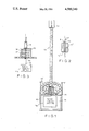
- FIG. 1 is a side elevational view, partially in section, of the sensor-carrier of the invention having an extended sensor and which also includes a schematic illustration of the sensor when it is in a packaged and retracted condition;
- FIG. 2 is a cross-sectional view of a partial region of the sensor-carrier illustrating two support bodies in an enlarged scale
- FIG. 3 is a detailed cross-sectional view in an enlarged scale of a part of the arrangement of FIG. 1.
- FIG. 1 illustrates schematically, partially in section, in side elevation, a sensor-carrier having a sensor in an extended operative position and also illustrates additionally schematically the same sensor in a packaged or inoperative position.
- the sensor-carrier includes a housing 10, in the lower region of which the required electronic components for operating the sensor are mounted and also, if need be, the energy supply source is mounted therein.
- An intermediate wall 20 separates the electronic component storage chamber 11 from the packaging chamber 21.
- the sensor 21 and sensor mounting means 13 are mounted, when in their inoperative position, that is during their traverse along the transport path, in particular during firing and setting down, in the illustrated retracted packaged condition.
- the reference number 13' indicates the sensor mounting means as packaged in a compact space.
- the packaging chamber 21 is closed by a cover, which has not been illustrated in FIG. 1 for purpose of clarity, for the purpose of protecting the sensor 12 and the retracted sensor mounting means 13.
- the cover can be blown off by known means, for example, by means of a pyrotechnical charge or by means of a mechanical spring, in order to permit the unfolding and extending of the sensor mounting means 13 for the purpose of positioning the sensor 12 into an operative position, so that the sensor 12 can "see” over obstacles, as, for example, rocks, bushes or grass at the location at which the sensor-carrier has been set down so that it can operate without disturbances. If the sensor 12 is set down in an elevated region it has the additional advantage of being capable of surveiling a larger region.
- the sensor mounting means 13 consists of a plurality of rotational symmetrical shaped adjoining support bodies 13" (FIG. 2) which abut against each other via flat end face surfaces when the sensor 12 is in an operative position (FIG. 1).
- Each one of the adjoining abutting support bodies 13" are provided with a central bore through which a flexible support means extends in a manner similar to a pearl necklace.
- the support means can take the form of a steel cable 17 which is provided with a sheathing 18.
- the sheathing 18 is loosely arranged between the sensor body 12 proper and a hat-shaped housing 15 (FIG. 3) which extends into the interior of the packaging chamber 21 and is mounted by means of two threaded bolts onto the intermediate wall 20.
- the steel cable 17 is fixedly secured to a disc 16 at one of its two ends.
- the disc 16 is biased by means of a coil spring 14 arranged inside of the hat-shaped housing 15.
- the coil spring 14 biases the steel cable 17 in such a way that the support bodies 13" mounted one on top of the next adjoining one along the sheathing 18, are pressed together between the sensor body 12 and the top surface of the hat-shaped housing 15 and thereby provide a sufficiently stable erect support structure for the sensor body 12 which support structure is also flexible.
- the biasing force of the coil spring 14 is overcome and the sensor mounting means 13 can be folded, as is illustrated schematically in FIG. 1, into a compact space in the packaging chamber 21.
- the non-illustrated cover secures the packaging chamber 21 and prevents the sensor mounting means 13 to unfold.
- each support body 13" By means of the centrally axially arranged bores 13'" on each support body 13" it is possible to thread an additional flexible cable 19 therethrough, which flexible cable 19 connects the sensor 12 with the electronic components mounted in the electronic components storage chamber 11.
- This electrical cable 19 transmits the electrical signals which are generated by the sensor 12 as a result of the sensed measured magnitudes for further processing in the electronic components.
- the sensed data received by the sensor 12 which is conducted in the form of electronic signals to the electronic components disposed in the storage space 11 are transmitted by each set down sensor 12 via radio signals to a central unit for further processing.
- the transmitting range of such a radio transmitter 11a mounted in the sensor-carrier depends from an optimum antenna arrangement, which means a favorable height above ground.
- either the cable 17 and/or a sheathing 18 of the sensor mounting means 13, which form a metal coil can be used as an antenna for the radio transmitter of the sensor-carrier.
Landscapes
- Engineering & Computer Science (AREA)
- General Engineering & Computer Science (AREA)
- Mechanical Engineering (AREA)
- Physics & Mathematics (AREA)
- General Physics & Mathematics (AREA)
- Arrangements For Transmission Of Measured Signals (AREA)
- Geophysics And Detection Of Objects (AREA)
- Investigating Materials By The Use Of Optical Means Adapted For Particular Applications (AREA)
Applications Claiming Priority (2)
| Application Number | Priority Date | Filing Date | Title |
|---|---|---|---|
| DE19833304070 DE3304070A1 (de) | 1983-02-07 | 1983-02-07 | Sensortraeger |
| DE3304070 | 1983-02-07 |
Publications (1)
| Publication Number | Publication Date |
|---|---|
| US4589340A true US4589340A (en) | 1986-05-20 |
Family
ID=6190190
Family Applications (1)
| Application Number | Title | Priority Date | Filing Date |
|---|---|---|---|
| US06/573,343 Expired - Fee Related US4589340A (en) | 1983-02-07 | 1984-01-24 | Sensor carrier |
Country Status (3)
| Country | Link |
|---|---|
| US (1) | US4589340A (de) |
| EP (1) | EP0115775A3 (de) |
| DE (1) | DE3304070A1 (de) |
Cited By (4)
| Publication number | Priority date | Publication date | Assignee | Title |
|---|---|---|---|---|
| EP0173001A3 (en) * | 1984-06-09 | 1990-05-02 | Dynamit Nobel Aktiengesellschaft | Reconnaissance system |
| US5070790A (en) * | 1989-03-14 | 1991-12-10 | Thomson-Csf | Target marker to attract projectiles provided with a homing head |
| WO2019057901A1 (en) * | 2017-09-22 | 2019-03-28 | 30Mhz B.V. | DEVICE AND SYSTEM FOR MONITORING |
| CN119508676A (zh) * | 2025-01-14 | 2025-02-25 | 四川工商学院 | 一种基于市政工程施工的排水管道量泥设备 |
Families Citing this family (1)
| Publication number | Priority date | Publication date | Assignee | Title |
|---|---|---|---|---|
| JP2501030Y2 (ja) * | 1993-03-29 | 1996-06-12 | 株式会社アイエル | 器具等の自在位置固定装置 |
Citations (3)
| Publication number | Priority date | Publication date | Assignee | Title |
|---|---|---|---|---|
| GB561665A (en) * | 1943-01-23 | 1944-05-30 | Frederick Fanning Ayer Pearson | Improvements relating to land mines or bombs |
| US3754508A (en) * | 1971-04-05 | 1973-08-28 | Avco Corp | Sensor employing a resistance variation detecting system |
| US4402271A (en) * | 1980-03-20 | 1983-09-06 | Societe Europeenne De Propulsion | Anti-tank mine with wide surface of action |
Family Cites Families (5)
| Publication number | Priority date | Publication date | Assignee | Title |
|---|---|---|---|---|
| GB660913A (en) * | 1949-03-29 | 1951-11-14 | Gen Electric Co Ltd | Improvements in or relating to aerials for portable radio apparatus |
| GB983560A (en) * | 1962-09-18 | 1965-02-17 | Polymathic Engineering Company | Supporting stand for instruments, tools and the like |
| US4367680A (en) * | 1963-10-31 | 1983-01-11 | William Howard Hart | Standoff munition |
| US3546961A (en) * | 1967-12-22 | 1970-12-15 | Gen Electric | Variable flexibility tether |
| DE2455341C3 (de) * | 1974-11-22 | 1980-07-03 | Messerschmitt-Boelkow-Blohm Gmbh, 8000 Muenchen | Verfahren zur Ermittlung des Windprofiles von Höhenwinden |
-
1983
- 1983-02-07 DE DE19833304070 patent/DE3304070A1/de not_active Withdrawn
-
1984
- 1984-01-07 EP EP84100113A patent/EP0115775A3/de not_active Withdrawn
- 1984-01-24 US US06/573,343 patent/US4589340A/en not_active Expired - Fee Related
Patent Citations (3)
| Publication number | Priority date | Publication date | Assignee | Title |
|---|---|---|---|---|
| GB561665A (en) * | 1943-01-23 | 1944-05-30 | Frederick Fanning Ayer Pearson | Improvements relating to land mines or bombs |
| US3754508A (en) * | 1971-04-05 | 1973-08-28 | Avco Corp | Sensor employing a resistance variation detecting system |
| US4402271A (en) * | 1980-03-20 | 1983-09-06 | Societe Europeenne De Propulsion | Anti-tank mine with wide surface of action |
Cited By (4)
| Publication number | Priority date | Publication date | Assignee | Title |
|---|---|---|---|---|
| EP0173001A3 (en) * | 1984-06-09 | 1990-05-02 | Dynamit Nobel Aktiengesellschaft | Reconnaissance system |
| US5070790A (en) * | 1989-03-14 | 1991-12-10 | Thomson-Csf | Target marker to attract projectiles provided with a homing head |
| WO2019057901A1 (en) * | 2017-09-22 | 2019-03-28 | 30Mhz B.V. | DEVICE AND SYSTEM FOR MONITORING |
| CN119508676A (zh) * | 2025-01-14 | 2025-02-25 | 四川工商学院 | 一种基于市政工程施工的排水管道量泥设备 |
Also Published As
| Publication number | Publication date |
|---|---|
| EP0115775A3 (de) | 1986-05-21 |
| EP0115775A2 (de) | 1984-08-15 |
| DE3304070A1 (de) | 1984-08-09 |
Similar Documents
| Publication | Publication Date | Title |
|---|---|---|
| US6584907B2 (en) | Ordnance firing system | |
| CA1209232A (en) | Terminal guidance method and a guided missile operating according to this method | |
| US6480115B2 (en) | Multiple hazard field marker and components therefor | |
| KR100616019B1 (ko) | 화기 점화 시스템 | |
| US4691636A (en) | Exploding missile | |
| US5979290A (en) | Mine clearing device | |
| US4589340A (en) | Sensor carrier | |
| US10495431B2 (en) | Containers for explosives and positioning apparatuses for the same | |
| CA2266312A1 (en) | Blast resistant and blast directing container assemblies | |
| US6853875B1 (en) | System for the combined handling, delivery and/or protection of multiple standardized containers and their controllable payloads | |
| US5497705A (en) | Zone-defense weapon system and method for controlling same | |
| FR2597757B1 (fr) | Perfectionnements a un extincteur a decharge rapide et a son procede de fabrication | |
| US3758052A (en) | System for accurately increasing the range of gun projectiles | |
| US4292861A (en) | Earth self-orienting apparatus | |
| CA2363424A1 (en) | Door breaching device with safety adapter | |
| US4722282A (en) | Payload-carrying projectile | |
| US10780997B1 (en) | Systems and methods for shock-resistant memory devices | |
| FI112702B (fi) | DDT-tyypin lasersytytin | |
| KR20210026368A (ko) | 정전기가 방지되는 천정 기중기 및 이를 이용한 유도탄의 인양 방법 | |
| KR102734104B1 (ko) | 원격 지뢰 활성 장치 및 이를 포함하는 원격 지뢰 시스템 | |
| US20090152402A1 (en) | Satellite, method and a fleet of satellites for observing a celestial body | |
| RU2001133126A (ru) | Способ стрельбы управляемым снарядом и система наведения управляемого снаряда | |
| EP0173001A3 (en) | Reconnaissance system | |
| JPH04292800A (ja) | センサ導線用の敷設装置を備えた地雷 | |
| AU2001269266B2 (en) | Proximity sensing device |
Legal Events
| Date | Code | Title | Description |
|---|---|---|---|
| AS | Assignment |
Owner name: RHEINMETALL GMBH, 125 ULMENSTR. 125 4000 DUESSELDO Free format text: ASSIGNMENT OF ASSIGNORS INTEREST.;ASSIGNORS:HELLWIG, ROLF;SEIDENSTICKER, JENS;KARIUS, KLAUS D.;REEL/FRAME:004221/0518 Effective date: 19840124 Owner name: RHEINMETALL GMBH, GERMANY Free format text: ASSIGNMENT OF ASSIGNORS INTEREST;ASSIGNORS:HELLWIG, ROLF;SEIDENSTICKER, JENS;KARIUS, KLAUS D.;REEL/FRAME:004221/0518 Effective date: 19840124 |
|
| REMI | Maintenance fee reminder mailed | ||
| LAPS | Lapse for failure to pay maintenance fees | ||
| STCH | Information on status: patent discontinuation |
Free format text: PATENT EXPIRED DUE TO NONPAYMENT OF MAINTENANCE FEES UNDER 37 CFR 1.362 |
|
| FP | Lapsed due to failure to pay maintenance fee |
Effective date: 19900520 |