US4585948A - Non-scanning integrated optical system with wide field of view search capability - Google Patents
Non-scanning integrated optical system with wide field of view search capability Download PDFInfo
- Publication number
- US4585948A US4585948A US06/475,676 US47567683A US4585948A US 4585948 A US4585948 A US 4585948A US 47567683 A US47567683 A US 47567683A US 4585948 A US4585948 A US 4585948A
- Authority
- US
- United States
- Prior art keywords
- detector
- eye
- multiaperture
- image
- optical system
- Prior art date
- Legal status (The legal status is an assumption and is not a legal conclusion. Google has not performed a legal analysis and makes no representation as to the accuracy of the status listed.)
- Expired - Fee Related
Links
- 230000003287 optical effect Effects 0.000 title claims abstract description 46
- 230000001537 neural effect Effects 0.000 claims abstract description 53
- 230000015654 memory Effects 0.000 claims abstract description 43
- 239000011159 matrix material Substances 0.000 claims abstract description 40
- 238000012545 processing Methods 0.000 claims abstract description 22
- 230000006870 function Effects 0.000 claims description 9
- 230000000694 effects Effects 0.000 claims description 6
- 230000008520 organization Effects 0.000 claims description 2
- 230000004044 response Effects 0.000 claims 1
- 238000001514 detection method Methods 0.000 abstract description 9
- 238000004422 calculation algorithm Methods 0.000 abstract description 8
- 238000005516 engineering process Methods 0.000 abstract description 2
- 210000000035 superposition eye Anatomy 0.000 description 32
- 210000000026 apposition eye Anatomy 0.000 description 30
- 239000000835 fiber Substances 0.000 description 21
- 238000000034 method Methods 0.000 description 17
- 230000004304 visual acuity Effects 0.000 description 15
- 230000008569 process Effects 0.000 description 11
- 241000238631 Hexapoda Species 0.000 description 10
- 238000005303 weighing Methods 0.000 description 10
- 230000008901 benefit Effects 0.000 description 8
- 238000003708 edge detection Methods 0.000 description 7
- 239000002245 particle Substances 0.000 description 7
- 238000012937 correction Methods 0.000 description 6
- 238000013461 design Methods 0.000 description 6
- 238000010586 diagram Methods 0.000 description 6
- 230000006872 improvement Effects 0.000 description 6
- 230000001629 suppression Effects 0.000 description 5
- 238000004519 manufacturing process Methods 0.000 description 4
- 239000013307 optical fiber Substances 0.000 description 4
- 238000003909 pattern recognition Methods 0.000 description 4
- 210000001525 retina Anatomy 0.000 description 4
- 230000002123 temporal effect Effects 0.000 description 4
- 230000002596 correlated effect Effects 0.000 description 3
- 230000000875 corresponding effect Effects 0.000 description 3
- 229910000078 germane Inorganic materials 0.000 description 3
- 238000013459 approach Methods 0.000 description 2
- 230000015572 biosynthetic process Effects 0.000 description 2
- 238000004364 calculation method Methods 0.000 description 2
- 238000009826 distribution Methods 0.000 description 2
- 230000005484 gravity Effects 0.000 description 2
- 230000010354 integration Effects 0.000 description 2
- 210000005036 nerve Anatomy 0.000 description 2
- 230000005855 radiation Effects 0.000 description 2
- 241001529572 Chaceon affinis Species 0.000 description 1
- 241000282412 Homo Species 0.000 description 1
- 206010042618 Surgical procedure repeated Diseases 0.000 description 1
- 238000007792 addition Methods 0.000 description 1
- 230000003321 amplification Effects 0.000 description 1
- 230000008859 change Effects 0.000 description 1
- 239000007795 chemical reaction product Substances 0.000 description 1
- 230000001427 coherent effect Effects 0.000 description 1
- 230000003750 conditioning effect Effects 0.000 description 1
- 238000010276 construction Methods 0.000 description 1
- 230000007423 decrease Effects 0.000 description 1
- 238000011161 development Methods 0.000 description 1
- 238000011156 evaluation Methods 0.000 description 1
- 238000002474 experimental method Methods 0.000 description 1
- 230000004907 flux Effects 0.000 description 1
- 238000005286 illumination Methods 0.000 description 1
- 238000003384 imaging method Methods 0.000 description 1
- 230000005764 inhibitory process Effects 0.000 description 1
- 238000009413 insulation Methods 0.000 description 1
- 239000012528 membrane Substances 0.000 description 1
- 210000004218 nerve net Anatomy 0.000 description 1
- 238000003199 nucleic acid amplification method Methods 0.000 description 1
- 239000003973 paint Substances 0.000 description 1
- 238000007781 pre-processing Methods 0.000 description 1
- 239000000047 product Substances 0.000 description 1
- 230000035945 sensitivity Effects 0.000 description 1
- 239000007787 solid Substances 0.000 description 1
- 241000894007 species Species 0.000 description 1
- 230000004083 survival effect Effects 0.000 description 1
- 230000001360 synchronised effect Effects 0.000 description 1
- 238000012360 testing method Methods 0.000 description 1
- 239000013598 vector Substances 0.000 description 1
- 239000003643 water by type Substances 0.000 description 1
Images


Classifications
-
- G—PHYSICS
- G02—OPTICS
- G02B—OPTICAL ELEMENTS, SYSTEMS OR APPARATUS
- G02B3/00—Simple or compound lenses
- G02B3/0006—Arrays
- G02B3/0037—Arrays characterized by the distribution or form of lenses
- G02B3/0043—Inhomogeneous or irregular arrays, e.g. varying shape, size, height
-
- G—PHYSICS
- G01—MEASURING; TESTING
- G01J—MEASUREMENT OF INTENSITY, VELOCITY, SPECTRAL CONTENT, POLARISATION, PHASE OR PULSE CHARACTERISTICS OF INFRARED, VISIBLE OR ULTRAVIOLET LIGHT; COLORIMETRY; RADIATION PYROMETRY
- G01J1/00—Photometry, e.g. photographic exposure meter
- G01J1/02—Details
- G01J1/04—Optical or mechanical part supplementary adjustable parts
- G01J1/0407—Optical elements not provided otherwise, e.g. manifolds, windows, holograms, gratings
- G01J1/0411—Optical elements not provided otherwise, e.g. manifolds, windows, holograms, gratings using focussing or collimating elements, i.e. lenses or mirrors; Aberration correction
-
- G—PHYSICS
- G01—MEASURING; TESTING
- G01J—MEASUREMENT OF INTENSITY, VELOCITY, SPECTRAL CONTENT, POLARISATION, PHASE OR PULSE CHARACTERISTICS OF INFRARED, VISIBLE OR ULTRAVIOLET LIGHT; COLORIMETRY; RADIATION PYROMETRY
- G01J1/00—Photometry, e.g. photographic exposure meter
- G01J1/02—Details
- G01J1/04—Optical or mechanical part supplementary adjustable parts
- G01J1/0407—Optical elements not provided otherwise, e.g. manifolds, windows, holograms, gratings
- G01J1/0422—Optical elements not provided otherwise, e.g. manifolds, windows, holograms, gratings using light concentrators, collectors or condensers
-
- G—PHYSICS
- G01—MEASURING; TESTING
- G01J—MEASUREMENT OF INTENSITY, VELOCITY, SPECTRAL CONTENT, POLARISATION, PHASE OR PULSE CHARACTERISTICS OF INFRARED, VISIBLE OR ULTRAVIOLET LIGHT; COLORIMETRY; RADIATION PYROMETRY
- G01J1/00—Photometry, e.g. photographic exposure meter
- G01J1/02—Details
- G01J1/04—Optical or mechanical part supplementary adjustable parts
- G01J1/0407—Optical elements not provided otherwise, e.g. manifolds, windows, holograms, gratings
- G01J1/0425—Optical elements not provided otherwise, e.g. manifolds, windows, holograms, gratings using optical fibers
-
- G—PHYSICS
- G01—MEASURING; TESTING
- G01J—MEASUREMENT OF INTENSITY, VELOCITY, SPECTRAL CONTENT, POLARISATION, PHASE OR PULSE CHARACTERISTICS OF INFRARED, VISIBLE OR ULTRAVIOLET LIGHT; COLORIMETRY; RADIATION PYROMETRY
- G01J1/00—Photometry, e.g. photographic exposure meter
- G01J1/02—Details
- G01J1/04—Optical or mechanical part supplementary adjustable parts
- G01J1/0407—Optical elements not provided otherwise, e.g. manifolds, windows, holograms, gratings
- G01J1/0437—Optical elements not provided otherwise, e.g. manifolds, windows, holograms, gratings using masks, aperture plates, spatial light modulators, spatial filters, e.g. reflective filters
-
- G—PHYSICS
- G01—MEASURING; TESTING
- G01J—MEASUREMENT OF INTENSITY, VELOCITY, SPECTRAL CONTENT, POLARISATION, PHASE OR PULSE CHARACTERISTICS OF INFRARED, VISIBLE OR ULTRAVIOLET LIGHT; COLORIMETRY; RADIATION PYROMETRY
- G01J1/00—Photometry, e.g. photographic exposure meter
- G01J1/42—Photometry, e.g. photographic exposure meter using electric radiation detectors
- G01J1/4228—Photometry, e.g. photographic exposure meter using electric radiation detectors arrangements with two or more detectors, e.g. for sensitivity compensation
-
- G—PHYSICS
- G01—MEASURING; TESTING
- G01S—RADIO DIRECTION-FINDING; RADIO NAVIGATION; DETERMINING DISTANCE OR VELOCITY BY USE OF RADIO WAVES; LOCATING OR PRESENCE-DETECTING BY USE OF THE REFLECTION OR RERADIATION OF RADIO WAVES; ANALOGOUS ARRANGEMENTS USING OTHER WAVES
- G01S3/00—Direction-finders for determining the direction from which infrasonic, sonic, ultrasonic, or electromagnetic waves, or particle emission, not having a directional significance, are being received
- G01S3/78—Direction-finders for determining the direction from which infrasonic, sonic, ultrasonic, or electromagnetic waves, or particle emission, not having a directional significance, are being received using electromagnetic waves other than radio waves
- G01S3/781—Details
-
- G—PHYSICS
- G01—MEASURING; TESTING
- G01S—RADIO DIRECTION-FINDING; RADIO NAVIGATION; DETERMINING DISTANCE OR VELOCITY BY USE OF RADIO WAVES; LOCATING OR PRESENCE-DETECTING BY USE OF THE REFLECTION OR RERADIATION OF RADIO WAVES; ANALOGOUS ARRANGEMENTS USING OTHER WAVES
- G01S3/00—Direction-finders for determining the direction from which infrasonic, sonic, ultrasonic, or electromagnetic waves, or particle emission, not having a directional significance, are being received
- G01S3/78—Direction-finders for determining the direction from which infrasonic, sonic, ultrasonic, or electromagnetic waves, or particle emission, not having a directional significance, are being received using electromagnetic waves other than radio waves
- G01S3/782—Systems for determining direction or deviation from predetermined direction
- G01S3/783—Systems for determining direction or deviation from predetermined direction using amplitude comparison of signals derived from static detectors or detector systems
-
- G—PHYSICS
- G02—OPTICS
- G02B—OPTICAL ELEMENTS, SYSTEMS OR APPARATUS
- G02B3/00—Simple or compound lenses
- G02B3/0006—Arrays
- G02B3/0037—Arrays characterized by the distribution or form of lenses
- G02B3/0056—Arrays characterized by the distribution or form of lenses arranged along two different directions in a plane, e.g. honeycomb arrangement of lenses
-
- G—PHYSICS
- G01—MEASURING; TESTING
- G01J—MEASUREMENT OF INTENSITY, VELOCITY, SPECTRAL CONTENT, POLARISATION, PHASE OR PULSE CHARACTERISTICS OF INFRARED, VISIBLE OR ULTRAVIOLET LIGHT; COLORIMETRY; RADIATION PYROMETRY
- G01J1/00—Photometry, e.g. photographic exposure meter
- G01J1/02—Details
- G01J1/0204—Compact construction
- G01J1/0209—Monolithic
Definitions
- This invention relates to optical systems for acquiring and processing information from a scene and in particular to a non-scanning, integrated multiaperture optical system that views and identifies objects of interest in large scenes the viewing of which requires a large field of view capability.
- the cited references describe two types of multiaperture optics that are useful for the applications indicated above. They are the apposition eye and the neural superposition eye.
- the apposition insect eye is a collimation system.
- a collimator is often lensless, e.g., for neutrons or gamma particles. Even if a lens is used like in an autocollimator, the property of light which is utilized is the fact that it propagates in a straight line.
- the apposition eye uses lenses not for image formation, but for definition of the field of view for an individual eyelet. The location of the image point is entirely determined by the fact that the light propagates in a straight line. One consequence of this is the decoupling of the focal length of the eye from the field of view of the eye. The field of view is determined by the curvature of the surface of the multiaperture eye.
- this surface is already utilized for determination of the optical properties of the lens rather than for definition of the field of view which is now determined by the focal length. (For a given f-number and a given eye diameter). The consequence is that in the case of the multiaperture system the focal length can be kept extremely short, which provides for a minimum depth for the total eye.
- the disadvantage of the apposition eye is the limited resolving power which, however can be made good by using a very large number of eyelets.
- the neural superposition eye is no longer a collimation system but an interference system. It forms a small image. Since an image is formed, the question is why not use one lens only and obtain better resolving power. Obviously the neural superposition eye should be only used for special applications where details of the image are not important. This eye necessarily must be target oriented and not detail oriented. If it is necessary to identify a target as such and to determine where it is located rather than to describe differences in similar targets then the neural superposition eye has advantages over the single aperture eye. The advantages discussed above for the apposition eye still apply to some degree for the neural superposition eye, namely the decoupling of the field of view from the focal length and the convex shape of the retina.
- multiaperture optics can be used for specialized applications where the location and recognition of the target is more important than detailed description of the target.
- Such applications would include all optical systems having space and complexity limiting requirements as with the air-to-air missiles, air-to-ground missiles, ground-to-air missiles, robots, space based sensors, security surveillance cameras mentioned above.
- the invention is an integrated multiaperture optical system that provides viewing of and object identification in a very large scene without scanning of the light gathering optics.
- the system has the advantages of having a very large field of view without scanning; greatly reduced space requirements; large scale integrated circuit construction; reduced complexity and manufacturing costs; and improved performance for certain applications. It is particularly suited to U.S. Air Force optical missile seeker applications.
- the integrated multiaperture optical system of the invention comprehends multiaperture light gathering optics that projects received electromagnetic wave energy onto a detection layer.
- the output of the detector layer is correlated and then processed by a data processing stage to identify objects of interest in a scene being viewed by the light gathering optics.
- the multiaperture light gathering optics consists of an array of eyelets, or lens apertures, each viewing a discrete region of the scene under surveillance.
- the lens aperture members can have optical configuations and orientations that effect either apposition or neural superpostition imaging on the detector layer.
- the array can consist of either type lens aperture members or a combination of them.
- the detector layer comprises a separate detector for each lens aperture member and each detector has a multiplicity of elements with each element having a separate output.
- Correlation is achieved in a correlation layer adjacent to the detector layer. It contains a memory for each detector element. There is an amplifier and analog/digital converter combination for each detector element that conditions and loads data received by the detector element into its associated correlation layer memory. Certain memories are interconnected in accordance with a hard wired program to effect neural superposition image processing.
- a processing layer adjacent to the correlation layer includes a memory matrix that accesses the correlation layer memories.
- the data processing layer also includes microprocessor circuitry that processes the data contained in the memory matrix in accordance with an object recognition routine and in accordance with algorithms for apposition and neural superposition modes of operations.
- the system is implemented by using very large scale integrated circuit techniques whereby correlation layer memories can be physically located directly below their associated detector elements.
- FIGS. 1a and 1b are respectively schematic illustrations of converging waves in single and multiaperture optics
- FIGS. 2a, 2b and 2c are respectively schematic illustrations of the single aperture eye, the superposition and neural superposition eye and the apposition eye;
- FIGS. 3a, 3b and 3c are respectively schematic illustrations of the suppression of scattered light in the single aperture eye, the neural superposition eye and the apposition eye;
- FIG. 4 is a schematic illustration of one presently preferred embodiment of the invention.
- FIG. 5 is a sectional view of an individual eyelet, or lens aperture member
- FIG. 6 is an illustration, partly in section, partly in phantom of the detector, correlation and processing layers of the embodiment of FIG. 4;
- FIG. 7 is a simplified function block diagram of the perceptual process of the multiaperture optic system comprehended by the invention.
- FIG. 8 is a block diagram of the fiber optic multiplexer of FIG. 7;
- FIGS. 9a, 9b and 9c illustrate image conditioning for pattern recognition in accordance with the principles of the invention
- FIG. 10 illustrates means for recognition coefficient determination
- FIG. 11 illustrates an image shown on several detectors in the neural superposition embodiment of the invention
- FIGS. 12a, 12b, 12c, 12d and 12e illustrate edge detection of an object in accordance with principles of the invention
- FIG. 13 is a mask for the edge detection process
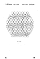
- FIGS. 14a and 14b illustrate a display of 7 eyelets and the arrangement of 7 fibers in each eyelet
- FIGS. 15a and 15b illustrate the display of 7 eyelets with shift correction and without shift correction
- FIGS. 16a, 16b and 16c illustrate the reconstruction of an edge in a 7 eyelet display
- FIG. 17 illustrates the layout of a 100 eyelet array
- FIG. 18 illustrates a neural superposition mask for use with the array of FIG. 17;
- FIG. 20 illustrates an original and a neural superpostion matrix
- FIG. 21 is a representation by dots of a neural superposition eye
- FIGS. 22a and 22b illustrate the result of an edge detection routine
- FIGS. 23a and 23b illustrate the correct interpretations of the representations of FIG. 22.
- FIG. 24 is a algorithm for an apposition eye
- FIG. 25 is an algorithm for a neural superposition eye.
- the present invention overcomes the limitations and disadvantages of single aperture optical systems by utilizing a system having multiaperture light gathering optics.
- FIG. 1a It is assumed that in FIG. 1a that the multiaperture system 22 has the same total aperture (the sum of all individual apertures) as the single lens system 21. Therefore, the same photon flux 25 is intercepted by both systems. The total energy delivered to the detectors 26, 27 is the same in both cases. The individual small lenses 24 have the same focal length as the one large lens 23. Therefore, the image plane is in both cases the same distance away from the lenses.
- each small lens Since the size of an image produced by a lens depends on the focal length but not on the diameter of the lens, each small lens will produce an image identical to the one produced by the large lens, albeit at much reduced intensity. If the object is infinitely (compared to the focal length) away, parts of the images produced by the small lenses will overlap. The individual intensities will add up and the end product should be identical as far as intensity and size is concerned. However, the quality of the two images is not the same. The reason is that the resolving power is determined by the lens diameter since the image is made possible by the diffraction of the light wave at the physical boundary (aperture) of the lens. The many different light waves going through the small lenses are not in phase with each other. Any interference occurring between them is random and does not, therefore, contribute to the image definition.
- FIG. 2 shows the case where again the total apertures are the same and the f-numbers of each small lens 24 is the same as the f-number of the large lens 23.
- the images obtained by the small lenses 24 are now much smaller than the image produced by the large lens 23.
- the image plane is also closer to the lenses, which makes the optical system more compact.
- the design is optimized properly as indicated in the figure, it can be arranged that (1) the field of view of the individual lenses do not overlap, (2) the size of the Airy disk is equal to the space available for it (detector size), which means the Airy disks produced by the many lenses ar not allowed to overlap.
- FIG. 3 illustrates this.
- the incoming wave 25 in FIG. 3a originates at an object point and converges into an Airy disk 28 probably smaller in size than the detector element 26.
- Diffuse light (noise) 30 may originate in the same regions in space as the object wave came from or it may have been scattered from anywhere into the ray path, so that it will be converged by the lens onto the same detector element as if it were originating from the object point.
- Noise and signal are usually distinguished by chopping the light beam. The intensity of the signal will then build up in time ⁇ -n, where n is the number of observed chops, while the noise will build up ⁇ - ⁇ n. If integrated for a sufficient amount of time, the signal-to-noise ratio will be improved to a sufficient extent that the signal can be identified.
- FIG. 3b shows the same situation for the superposition image.
- the cone 31 which intercepts the scattered radiation 32 is smaller, but so is the cone which intercepts the signal. Therefore signal-to-noise is not changed.
- the size of the Airy disk 33 is now the same as the detector 34. Therefore, while the signal-to-noise is, in this case, no better and no worse than for the single aperture system, the overall resolution also should be the same.
- such a multiaperture system would require precise alignment of all the individual lenses to form a correct superposition image. Therefore, such a system is not very practical.
- FIG. 3c shows the situation in case of the apposition image.
- the projections of the Airy disk 35 and detector 36 (which are the same size) now fill the FOV entirely.
- the signal-to-noise ratio is still the same as in FIG. 3b.
- the signal-to-noise ratio would be improved by a factor of ⁇ 10, while an increase of the area of a single lens would not result in an improvement of signal to noise (assuming the scattering particles are homogeneously distributed).
- the differences are that in the multiaperture system, the 10 light waves coming from the scatered particles are not in phase, but are random while in the single aperture system it is only one lightwave which is now collected through a 10 times larger aperture area exactly as the signal wave is.
- FIG. 4 One presently preferred embodiment of the invention is illustrated schematically by FIG. 4. It comprises the multiaperture optic array formed of lenses 40, tubular supports 41, detection layer 42, correlation layer 45 and processing layer 44. Each individual lens 40 forms an image on the detection layer 41.
- the detection layer contains individual detectors, typically 100 per lens.
- the correlation layer 43 is a large scale integration (LSI) structure which contains one amplifier per detector and one memory element per detector. The output from each detector is amplified and converted in a number which is stored in the respective memory element. Amplifier, A-D converter, and memory element are physically located underneath each detector in the correlation layer as shown in FIG. 6. Certain detectors will view the same location in space ("equivalent" detectors).
- LSI large scale integration
- the content of the memory elements of "equivalent” detectors need to be added and therefore are connected with a wire (hard wired instruction) in the correlation layer.
- the results of all these additions are stored in a memory matrix (a regular computer core) which is physically located in the processing layer.
- the contents of this memory matrix can be accessed and rearranged using state-of-the-art circuitry, like any microprocessor would do. Therefore, the processing layer contains similar circuitry, as state-of-the-art microprocessors. This circuitry can perform image evaluation on the contents of the memory matrix.
- FIG. 5 shows a typical eyelet, or lens aperture member 50. It comprises a cylindrical member 51, an aperture stop 52, lenses 53, 54, and output optical fibers 55. The end surface of fibers 55 are polished and receive electromagnetic wave energy that is transmitted by the fibers to associated detectors.
- FIG. 6 shows details of the detector layer 42 (partially in section), the correlation layer 43 (partially in phantom) and the processing layer 44 (also partially in phantom.)
- Detector layer 42 comprises a multiplicity of detector elements 40, each of which is cylindrical in shape and consists of a reflecting layer 64, a transparent insulation layer 61, a transparent core 62 and a photosensitive layer 63. Typical diameter of one fiber detector is 100 micrometers. A great many of these fiber detectors are glued together to form the detector layer.
- the output from photosensitive layer 63 feeds amplifier 65 in correlation layer 43.
- the output of amplifier 65 is analog to digital converted by analog/digital converter 66 and read into memory 67. All memories in the correlation layer are accessed by the programming layer memory matrix 68.
- Amplifier 65, analog/digital converter 66 and memory 67 are fabricated in accordance with very large scale integrated circuit techniques and are physically positioned beneath detector element 60.
- FIG. 7 illustrates a simplified functional block diagram of the perceptual process of the invention
- FIG. 8 is a block diagram of the multiplexer shown in FIG. 8.
- Each object necessarily has to have a boundary. In an image, this boundary is recognized as an edge.
- the combination of the edges form an outline of an object.
- an object is recognizable just by such a outline drawing although it does not contain all the information necessary to describe the object completely.
- a complete description of the object would be obtained by a picture of the object (e.g., a color photograph). It is obvious that for some applications an outline drawing is sufficient and for other application, a picture is required.
- Digitizing of an image produced by a large single lens can, in principle, be accomplished in two different ways, namely by temporal acquisition and spatial acquisition.
- Temporal acquisition involves reading and digitizing one pixel at a time and feeding this information through one line into a memory where it can be stored as a linear array or a matrix, depending on the architecture of the memory.
- Spatial acquisition would involve reading and digitizing all the pixels simultaneously and feeding them into the memory with a number (n) of lines, where n is equal to the number of pixels.
- temporal acquisition is a television camera, while a focal plane array would be an example for spatial acquisition if it could be read simultaneously; and even if this could be done most computers lack the number of input ports to handle such a flow of information.
- FIG. 4 shows how such a detection system may be realized by large scale integration.
- the lenses 40 supported by small tubes 41 form an image (or Airy disk) on the detectors on the surface of the detection layer 42.
- a memory cell is located directly under each detector.
- the memory cells are interconnected with each other in the correlation layer to form a complete memory.
- the memory can be read by the processing layer which may comprise a ROM with programmed steps how to evaluate the information.
- the output of the processing layer relays the results of these calculations, to the maincomputer of the vehicle. These results may contain the identification of the target, its position, speed, and any other desired information.
- the image is represented by a set of numbers forming a two or more (e.g., gray scale) dimensional matrix.
- the number of elements of this matrix reflects the number of eyelets (there may be more than one element per eyelet), but this number is necessarily limited by practical considerations.
- the number of elements can be as large as desired. The upper limit is just the collection time one is willing to allow and the size of the memory.
- FIG. 9(a) shows a matrix describing an image.
- This matrix may be the result of the readout of the eyelets of an apposition eye. Each number may reflect the intensity seen by one individual eyelet.
- a value (n) will be set to ⁇ 0 ⁇ if n 4 and to ⁇ 1 ⁇ if n 4.
- the resulting matrix consisting of only zeros and ones is also shown in FIG. 9(a).
- the image obtained if the ones are represented by points and the zeros are ignored is shown next to the matrix in FIG. 9(a). If displayed on the screen a human observer will recognize the image as a triangle. For a machine a procedure has to be developed so that it will also recognize this figure as a triangle.
- this is done by computing a ⁇ recognition coefficient ⁇ (N) which is one number and will adequately and uniquely describe the shape of the object.
- N the recognition coefficient (N) is computed as follows: ##EQU1## where j is the column number, i is the row number, L the number of rows, and K the total number of columns. I(i,j) is either 0 or 1.
- the weighing factor W(i,j) for the ij th element is computed as follows:
- the weighing factor mask is aligned on the matrix that column number ⁇ 1 ⁇ covers the most left sided ⁇ 1 ⁇ of the matrix and row number ⁇ 1 ⁇ covers the highest ⁇ 1 ⁇ of the matrix. This is illustrated in FIG. 10, which shows the weighing mask and the position of the triangle. Each element of the matrix is divided by its corresponding member of the weighing mask and the results are added. Since the eye is hexagonal and the weighing mask is a regular matrix, only every second member of the weighing mask is actually used.
- the result of the computation is one number, the recognition coefficient, which is unique for the shape of the object.
- the result in the example shown is:
- the recognition coefficient for common shapes need to be determined once for each eye after it is produced. If they are permanently entered in a ROM the eye will be able to detect and recognize objects of a given shape.
- the three types are:
- FIG. 2 shows these three types of eyes in addition to the regular single aperture eye.
- the field of view of the individual eyelets are adjacent and not, or only insignificantly, overlapping.
- An object which is too small to fill the entire field of view of the individual eyelet is preceived as one point filling the whole field of view being located in the center of the field of view. Therefore, in order for two points to be resolved, they have to be far enough apart so that they fall into the field of views of two different eyelets.
- the resolving power of such an eye is, therefore, inversely proportional to the diameter of individual lens, assuming that the detector is located at the focal point of the lens.
- Such a lens then acts as a collimator, defining a parallel bundle, having the same diameter as the lens, as field of view.
- detectors there may be more than one detector in the apposition eye, although obviously only one is necessary for determination if there is an object point or not.
- the other detectors may be used for the same purpose, either duplicating the first one, or more likely detecting the same object point at a different wavelength.
- the size of the Airy disk is on the order of the diameter of the one (although fused) rhabdom. If the Airy disk were much smaller, the eyelet could resolve two different points within its field of view, but the detector would add them electronically back together. To avoid this, an apposition eye having separated rhabdomeres would be the next step in evolution. It is reasonable to assume that the rhabdomeres would separate first without the lens being enlarged and at a later step the lenses would get larger and the detector plane would move out of the focal point into an image plane, thus evolving into the superposition eye. Therefore, as an intermediate eye, creating an Airy disk in the order of the diameter of the cluster of rhabdomeres, but the rhabdomeres are now separated.
- the Airy disk will be displaced to one side.
- the seven individual rhabdomeres will be unevenly illuminated.
- a center of gravity of illumination can, therefore, be calculated, which will reveal the true position of the object within the field of view.
- the detector plane In the case of the superposition eye, the detector plane is moved towards a position between 1f and 2f (f: focal length of the lens). The effect is that now a real image is formed.
- the size of this image can be considerably larger than the diameter of the lens. If the walls of the eyelets are transparent (clear zone) the image spreads over the detector of the neighboring lens. The same happens with the images created by the neighboring eyelets. Therefore, many images overlay (are superpositioned). Of course the individual images must be carefully aligned to make an object recognizable.
- the detector plane In the case of neural superposition, the detector plane is located close to the focal point of the lens, but not at the focal point. The consequence is that a small, although poorly resolved, image is obtained within the eyelet.
- the walls of the eyelet may be opaque, therefore no optical superposition takes place.
- the field of view of the neural superposition eye is smaller than the one of the superposition eye, but larger than the one of the apposition eye.
- FIG. 11 shows the situation for the neural superposition eye.
- the field of view of the individual eyelets overlaps.
- the overlap is only partial, which means the optical axes are offset against each other.
- the offset ( ⁇ ) being:
- x is the field of view of an individual eyelet and n is the number of detectors in one linear row.
- the shaded area in FIG. 11 is the image of a rectangular object. If one were to describe the right edge of this rectangle using eyelet #1, only the detector #4 (1.4) would give information on the location of the edge.
- each individual image is poorly defined. The resolving power of the total eye depends, in contrast to the apposition eye, now linearly on the diameter of the lens of an individual eyelet.
- the requirement was that the Airy disk has a diameter equal to the detector cluster diameter (the distance from detectors 1 to 4).
- the requirement is that the diameter of the Airy disk is equal the diameter of one detector, which means about a factor of five smaller. Therefore, the diameter of the individual lenses has to be a factor of five larger. If the smallest size of the detector is given by practical limitations, this new diameter is the optimum diameter for resolution, even for a single aperture eye. Any larger lens diameter would not increase the resolving power of the eye.
- the image would need to be spread out over a larger number of detectors and, therefore, the focal length needs to be increased, which in turn, would require a larger diameter of the lens in order to keep the f-number the same.
- Short focal length and convex image plane mean small depth of the overall eye, which was an overriding requirement for the evolution of the insect eye. If it is necessary to cover a substantial part of the surface of a missile with an optical sensor, the same requirement would logically prevail.
- the conclusion applied is that the neural superposition eye more redundant than the apposition eye.
- the loss of one eye means more loss of information in case of the apposition eye.
- the apposition eye has a better resolving power. How much better depends on the degree of redundancy the neural superposition eye has, which means how often is the same point of an object sampled by a different detector. Obviously, there is an optimum, depending on the application.
- the image of either the apposition eye or the superposition eye is represented as a matrix of numbers.
- the recognition of an object can then simply be done by cross correlation with stored information describing an identical or very similar object. This method is indeed unambiguous. However, if complicated shapes are involved the deviation from the correlation coefficient which can be tolerated becomes smaller and smaller the more complicated the shape of the object turns out to be.
- FIG. 12 shows a simple example.
- the image matrix is shown after all values were set to either one or zero. If the ones are represented by dots and the zeros are ignored, the attached image is obtained. Then the edge detection process using the mask shown in FIG. 13 is applied. The resulting image matrix and the representation of ones by points is shown next in FIG. 12 ((c) and (d)).
- a subroutine which connects all points by a straight line is then applied and the final image is obtained as shown in FIG. 12 (e).
- the multiaperture eye is target oriented not scene oriented. This means the eye is specialized to sort out a target and recognize it rather than collect all available information in great detail and reconstruct the total scene as an image of reality. Therefore, for the multiaperture eye two major sources of noise exist. This is actual noise and another type of noise designated ⁇ information noise. ⁇ This ⁇ information noise ⁇ is all the unwanted information (detail) which is collected but is not germane to the target. Optical preprocessing as discussed above is one way to reduce this ⁇ information noise. ⁇ The part of the surplus information which is strongly correlated (e.g., an edge) will contribute to the image.
- An initial attempt to remove noise may be to define a threshold. Any number in the image matrix smaller than the threshold number will be set to zero. Of course this removes not only noise but signal as well. If the signal to noise ratio 1, then thresholding is of course not acceptable. Therefore, other noise suppression methods have to be used.
- the neural superposition eye has considerable less resolving power than the apposition eye. Therefore, to justify its use, the target would have to be so noisy that a higher resolving power would be useless. The high redundancy of the neural superposition eye will have to be used for noise supression.
- FIG. 3 shows such a situation. Assume that one of the small particles will scatter a light beam coming from the side into the field of view of an individual detector. The detector will detect this as a contribution to the energy coming from the target point.
- the light cone depicted in FIG. 3(b) represents the light cone accepted by one of the seven detectors in one eyelet of the neural superposition eye. If one particle only were to scatter the beam coming from the side, only one detector is affected. Of course all particles scatter but the waves are not coherent and it is not reasonable that all of their Pointing Vectors will be parallel.
- An increase in the aperture which means in this case an increase in the number of eyelets indeed increases the S/N ratio.
- the optical system shown therein consists of a 2 mm diameter plano-convex lens 54 of 2 mm focal length and a 1 mm diameter plano-convex lens 53 having 1 mm focal length. Both can be moved in respect to each other, so that they can be arranged in the form of a Kepler telescope, which would form a real image in the detector plane. They can be arranged also with both focal points coinciding with overlapping focal length.
- the detector system consists of a 7-piece bundle of optical fibers which will carry the light outside the eyelet where this fiber bundle can be spread apart into the individual fibers which can be connected to individual detectors.
- the fibers can be optically insulated from each other or not. Diameter of one fiber is 140 ⁇ m.
- the analog output of the detectors can be digitized and manipulated in a computer.
- the individual eyelets discussed above are arranged in a bundle. In one embodiment of the invention it is a bundle of seven, while in a second embodiment it is a bundle of close to 100.
- the signals coming from the detectors can be digitized and manipulated in a computer.
- the signals from the center fibers would be used to assemble a coarse image which can be displayed on a video terminal.
- the location of each picture point which is as large in size, as the total field of view of an individual eyelet, can be better defined by checking the intensity distribution in the first maximum ring. That means the display point can be moved (slightly) into a location which corresponds better to the actual location of image point of a physical point source, which would create the particular diffraction pattern which was observed. The resulting image will be sharper than the original coarse image.
- FIG. 14(b) shows the arrangement of the seven fibers into a bundle. Each eyelet contains one of these bundles.
- the squares of FIG. 14(a) represent the FOV of an individual eyelet and are assigned spaces on the video screen.
- the display point is free to move within the square as required.
- the intensity of the display point is coded as indicated on the Figure.
- Each square is fed by a different eyelet. If only the center fiber information is used the display points are automatically displayed on the center of the square. If the real point which creates the image point is not located on the axis of the eyelet, but towards the side of the field of view, the single detector could not tell the difference (only the intensity would be reduced somewhat, which, however, could have other causes), therefore, the display point has to be located in the center of the square for want of better information.
- FIG. 15 shows the image of an edge. In FIG. 15(a) the display points are centered and in FIG. 15(b) the display points move to an improved location.
- the real point is indeed a point (an object smaller than the field of view of an individual eyelet) with this signal processing, and improvement in resolving power can be achieved which goes beyond the theoretical resolving power of the eyelet.
- the real point is a gray area which fills the whole field of view, (as a part of a big object) no improvement of resolving power occurs.
- the display points will remain centered in their squares, since the diffraction pattern will have a symmetrical intensity distribution.
- an improvement of resolution is not required in a case like this. Only the edges of a large object are of interest, and at the location of the edges there will be eyelets which have their field of view only partially filled. And here, of course, the improvement process will function again.
- the 100 eyelet embodiment is therefore divided into 68 neural superposition eyelets and 32 apposition eyelets.
- the neural superposition eyelets have a field of view of 12 degrees. Each optical axis is offset from its neighbor by 2 degrees with little overlap to the neighboring field of view.
- FIG. 17 shows this embodiment. In FIG. 17 all eyelets with a number 76 after the comma are apposition eyelets, the rest are neural superposition eyelets.
- each optical fiber coming out of each eyelet is routed to a detector panel where each optical fiber is terminated at a solid state fiberoptic detector which produces an output voltage proportional to the light intensity entering the fiber.
- This output voltage goes through a calibration potentiometer (FIG. 8) which allows for adjustment of each one of the fibers for equal output when the complete eye is viewing a uniform light source (no object of recognition).
- the output of each calibration potentiometer is fed to one channel of a 658 channel analog multiplexer which sequentially scans 658 fibers.
- FIG. 8 shows the block diagram of the multiplexer. The scan rate is adjustable by changing the clock frequency of the counter which drives the multiplexers.
- all multiplexer channel outputs are tied to one common output which is amplified and then externally fed to the computer analog-to-digital converter.
- the clock which causes the multiplexer to scan is also externally connected to the A-D converted to maintain synchronous operation.
- the output voltage of the particular channel being sampled is displayed by a front panel digital voltmeter.
- Counter and front panel digital readouts are also provided to indicate which eyelet and which fiber within that eyelet is being sampled. Additional front panel controls enable manual or automatic channel advance, reset to channel 0, single or continuous sweep modes, and start and stop of the sweep.
- the multiplexer is only used in order to be able to utilize a microcomputer (HP85) as it exists.
- the desirable situation would, of course, be to feed each detector output directly (and parallel) into a memory location.
- One of the next steps is to built or find a microcomputer which has 1000 input ports.
- FIG. 7 gives a simplified flow diagram at the present set-up. The initial noise suppression is done by thresholding only as it was demonstrated in FIG. 9.
- the apposition part or the neural superposition part of the eye can be used.
- the functioning of the apposition eye has already been described with the 7 eyelet model.
- the shift correction, which may or may not be applied is one of the subroutines.
- Another subroutine would be to connect all points with lines and display the result on the video screen.
- the ⁇ Cortical Processing ⁇ the coefficients which were computed with a subroutine are matched with stored coefficients and conclusion are drawn.
- a neural superposition mask (FIG. 18) has to be applied to the acquired image matrix.
- the neural superposition image of the (i,j) the neural-commatidium will be: ##EQU2## where w1, w2, w3, w4 in the above equation are weighing functions which are determined by the sensitivity of the eye.
- NSP (Neural Superposition) processing is performed by convolving the image of the detector array (FIG. 19) with the above NSP mask (FIG. 18).
- the neural superposition consists of superimposing the NSP mask over a portion of the original image, multiplying each fiber element by the corresponding mask element, summing the products, then creating in a new matrix a new image element whose location corresponds to the element forming the center of the NSP mask.
- the mask is moved over each element of the original image matrix and the procedure repeated to create the neural superposition image point by point.
- FIG. 20 shows the original image matrix and the result of the neural superposition procedure. Due to the limited screen size it is not advantageous to display the 2nd and 3rd decimal point, although it is stored in the machine. For this reason the image points are again shown as dots in FIG. 21.
- the edge can now be discovered which is the boundary line between an illuminated field and on a dark field.
- One row of eyelets is inoperative for yet undetermined reasons.
- the illuminated points at the boundary of the eye stem from a software imperfection. Since these eyelets are at the very boundary of the total eye, they do not have the benefit of information input of more eyelets to the right. Therefore, not all weighing functions are available and the ones which are available are influenced by the bright points to the left.
- the next step is to detect the edge with the previously described edge detection scheme.
- the result is seen in FIG. 22 in dot representation and line representation. Examining the neural superposition process closer, it is realized that always two parallel rows of eyelets will detect the edge. Therefore, the line representation should account for this fact. This had been done in FIG. 23.
- the correct interpretation of the dot representation is shown, which amounts to two edges. The true location of the edge must be between the two which is indicated in FIG. 23, type B.
- the algorithm used for the apposition eye is shown in FIG. 24 and the algorithm for the neural superposition eye in FIG. 25. Both algorithms use the same subroutine for contrast embodiment.
- the shape of the target is known beforehand.
- the environment it is supposed to survey is known and an intruder constitutes a change in this environment and is so detected.
- This shape is of minor importance, the major importance is the fact that he is there, and where he is. If a picture of him is also desired the above information can be used to direct a regular (roving) camera to him.
- the multiaperture security surveillance camera has a 360° field of view and is of course non-roving.
- the target is and it is not so important what the exact shape of the target is.
- the approximate shape of the target is known beforehand.
- the shape of the target is known beforehand. Even if it should be a complex shape it can be approximated with a simple but target specific shape, so that the robot will find the correct part.
- some of the sensor can be used for shape and the others can be used for color detection.
Abstract
Description
W(i,j)=j+(i-1)×K
N=1/6 +1/20+1/22+1/34+1/38+1/48+1/54+1/62+/1/70+1/76+1/77+1/78+1/79+1/80+1/81+1/82+1/83+1/84+1/85+1/86=0.523625381589
β=X/n
P.sub.o =P.sub.s.sup.n ; P.sub.s <1
Claims (8)
Priority Applications (2)
| Application Number | Priority Date | Filing Date | Title |
|---|---|---|---|
| US06/475,676 US4585948A (en) | 1983-03-15 | 1983-03-15 | Non-scanning integrated optical system with wide field of view search capability |
| US06/555,803 US4585937A (en) | 1983-03-15 | 1983-11-28 | High efficiency fiber-shaped detector |
Applications Claiming Priority (1)
| Application Number | Priority Date | Filing Date | Title |
|---|---|---|---|
| US06/475,676 US4585948A (en) | 1983-03-15 | 1983-03-15 | Non-scanning integrated optical system with wide field of view search capability |
Related Child Applications (1)
| Application Number | Title | Priority Date | Filing Date |
|---|---|---|---|
| US06/555,803 Continuation-In-Part US4585937A (en) | 1983-03-15 | 1983-11-28 | High efficiency fiber-shaped detector |
Publications (1)
| Publication Number | Publication Date |
|---|---|
| US4585948A true US4585948A (en) | 1986-04-29 |
Family
ID=23888626
Family Applications (1)
| Application Number | Title | Priority Date | Filing Date |
|---|---|---|---|
| US06/475,676 Expired - Fee Related US4585948A (en) | 1983-03-15 | 1983-03-15 | Non-scanning integrated optical system with wide field of view search capability |
Country Status (1)
| Country | Link |
|---|---|
| US (1) | US4585948A (en) |
Cited By (19)
| Publication number | Priority date | Publication date | Assignee | Title |
|---|---|---|---|---|
| US4893025A (en) * | 1988-12-30 | 1990-01-09 | Us Administrat | Distributed proximity sensor system having embedded light emitters and detectors |
| US5015844A (en) * | 1989-02-17 | 1991-05-14 | The United States Of America As Represented By The Secretary Of The Air Force | Optical surveillance sensor apparatus |
| US5260826A (en) * | 1992-01-21 | 1993-11-09 | Physical Optics Corporation | Nonscanning sectioning microscope |
| WO1995004299A1 (en) * | 1993-08-03 | 1995-02-09 | Northrop Grumman Corporation | Non-mechanical step scanner system for electro-optical sensors |
| US5463566A (en) * | 1991-08-21 | 1995-10-31 | Alenia Aeritalia & Selenia S.P.A. | Preprocessor for detection of punctiform sources in infrared scenarios |
| US5719623A (en) * | 1993-03-23 | 1998-02-17 | Hamamatsu Photonics K.K. | Streak tube |
| US5864836A (en) * | 1995-10-12 | 1999-01-26 | Universita' Degli Studi Di Roma "La Sapienza" | Optically programmable optoelectronic cellular neural network |
| US6567219B1 (en) * | 1999-08-13 | 2003-05-20 | Semiconductor Energy Laboratory Co., Ltd. | Laser irradiation apparatus |
| US20030138999A1 (en) * | 1999-08-13 | 2003-07-24 | Semiconductor Energy Laboratory Co., Ltd. | Laser irradiation apparatus |
| US6657719B1 (en) * | 1999-11-09 | 2003-12-02 | The United States Of America As Represented By The Department Of Commerce | Fiber optic tomographic plasma uniformity monitor |
| US6804470B1 (en) * | 1997-03-04 | 2004-10-12 | Stuart Gary Mirell | Energy-depleted radiation apparatus and method |
| US20040239584A1 (en) * | 2003-03-14 | 2004-12-02 | Martin Edelmann | Image display device |
| WO2009040792A1 (en) * | 2007-09-26 | 2009-04-02 | Elbit Systems Ltd. | Wide field of view optical tracking system |
| WO2011045324A2 (en) | 2009-10-14 | 2011-04-21 | Fraunhofer-Gesellschaft zur Förderung der angewandten Forschung e.V. | Device, image processing device and method for optical imaging |
| US8885177B2 (en) | 2007-09-26 | 2014-11-11 | Elbit Systems Ltd. | Medical wide field of view optical tracking system |
| US20160291115A1 (en) * | 2015-03-30 | 2016-10-06 | Luminit Llc | Compound Eye Laser Tracking Device |
| CN111066263A (en) * | 2017-07-21 | 2020-04-24 | 加州理工学院 | Ultra-thin plane lens-free camera |
| US10890417B2 (en) | 2015-03-30 | 2021-01-12 | Luminit Llc | Compound eye laser tracking device |
| US11882371B2 (en) | 2017-08-11 | 2024-01-23 | California Institute Of Technology | Lensless 3-dimensional imaging using directional sensing elements |
Citations (5)
| Publication number | Priority date | Publication date | Assignee | Title |
|---|---|---|---|---|
| US4114037A (en) * | 1977-05-16 | 1978-09-12 | Northern Telecom Limited | Multiple lens system for an optical imaging device |
| US4227212A (en) * | 1978-09-21 | 1980-10-07 | Westinghouse Electric Corp. | Adaptive updating processor for use in an area correlation video tracker |
| US4270047A (en) * | 1978-04-28 | 1981-05-26 | Canon Kabushiki Kaisha | Information detecting apparatus |
| US4272783A (en) * | 1977-11-02 | 1981-06-09 | Saab-Scania Ab | Correlation follower for tracking an object |
| US4410804A (en) * | 1981-07-13 | 1983-10-18 | Honeywell Inc. | Two dimensional image panel with range measurement capability |
-
1983
- 1983-03-15 US US06/475,676 patent/US4585948A/en not_active Expired - Fee Related
Patent Citations (5)
| Publication number | Priority date | Publication date | Assignee | Title |
|---|---|---|---|---|
| US4114037A (en) * | 1977-05-16 | 1978-09-12 | Northern Telecom Limited | Multiple lens system for an optical imaging device |
| US4272783A (en) * | 1977-11-02 | 1981-06-09 | Saab-Scania Ab | Correlation follower for tracking an object |
| US4270047A (en) * | 1978-04-28 | 1981-05-26 | Canon Kabushiki Kaisha | Information detecting apparatus |
| US4227212A (en) * | 1978-09-21 | 1980-10-07 | Westinghouse Electric Corp. | Adaptive updating processor for use in an area correlation video tracker |
| US4410804A (en) * | 1981-07-13 | 1983-10-18 | Honeywell Inc. | Two dimensional image panel with range measurement capability |
Cited By (33)
| Publication number | Priority date | Publication date | Assignee | Title |
|---|---|---|---|---|
| US4893025A (en) * | 1988-12-30 | 1990-01-09 | Us Administrat | Distributed proximity sensor system having embedded light emitters and detectors |
| US5015844A (en) * | 1989-02-17 | 1991-05-14 | The United States Of America As Represented By The Secretary Of The Air Force | Optical surveillance sensor apparatus |
| US5463566A (en) * | 1991-08-21 | 1995-10-31 | Alenia Aeritalia & Selenia S.P.A. | Preprocessor for detection of punctiform sources in infrared scenarios |
| US5260826A (en) * | 1992-01-21 | 1993-11-09 | Physical Optics Corporation | Nonscanning sectioning microscope |
| US5719623A (en) * | 1993-03-23 | 1998-02-17 | Hamamatsu Photonics K.K. | Streak tube |
| WO1995004299A1 (en) * | 1993-08-03 | 1995-02-09 | Northrop Grumman Corporation | Non-mechanical step scanner system for electro-optical sensors |
| US5448395A (en) * | 1993-08-03 | 1995-09-05 | Northrop Grumman Corporation | Non-mechanical step scanner for electro-optical sensors |
| US5864836A (en) * | 1995-10-12 | 1999-01-26 | Universita' Degli Studi Di Roma "La Sapienza" | Optically programmable optoelectronic cellular neural network |
| US6804470B1 (en) * | 1997-03-04 | 2004-10-12 | Stuart Gary Mirell | Energy-depleted radiation apparatus and method |
| US7910416B2 (en) | 1999-08-13 | 2011-03-22 | Semiconductor Energy Laboratory Co., Ltd. | Laser irradiation apparatus |
| US6567219B1 (en) * | 1999-08-13 | 2003-05-20 | Semiconductor Energy Laboratory Co., Ltd. | Laser irradiation apparatus |
| US20030138999A1 (en) * | 1999-08-13 | 2003-07-24 | Semiconductor Energy Laboratory Co., Ltd. | Laser irradiation apparatus |
| US7160765B2 (en) | 1999-08-13 | 2007-01-09 | Semiconductor Energy Laboratory Co., Ltd. | Method for manufacturing a semiconductor device |
| US20070111549A1 (en) * | 1999-08-13 | 2007-05-17 | Koichiro Tanaka | Laser irradiation apparatus |
| US6657719B1 (en) * | 1999-11-09 | 2003-12-02 | The United States Of America As Represented By The Department Of Commerce | Fiber optic tomographic plasma uniformity monitor |
| US20040239584A1 (en) * | 2003-03-14 | 2004-12-02 | Martin Edelmann | Image display device |
| US8885177B2 (en) | 2007-09-26 | 2014-11-11 | Elbit Systems Ltd. | Medical wide field of view optical tracking system |
| US8384912B2 (en) | 2007-09-26 | 2013-02-26 | Elbit Systems Ltd. | Wide field of view optical tracking system |
| WO2009040792A1 (en) * | 2007-09-26 | 2009-04-02 | Elbit Systems Ltd. | Wide field of view optical tracking system |
| US8593647B2 (en) | 2007-09-26 | 2013-11-26 | Elbit Systems Ltd. | Wide field of view optical tracking system |
| EP2432213A1 (en) * | 2009-10-14 | 2012-03-21 | Fraunhofer-Gesellschaft zur Förderung der angewandten Forschung e.V. | Device, image processing device and method for optical imaging |
| WO2011045324A2 (en) | 2009-10-14 | 2011-04-21 | Fraunhofer-Gesellschaft zur Förderung der angewandten Forschung e.V. | Device, image processing device and method for optical imaging |
| EP2429176A1 (en) * | 2009-10-14 | 2012-03-14 | Fraunhofer-Gesellschaft zur Förderung der angewandten Forschung e.V. | Device, image processing device and method for optical imaging |
| US20110228142A1 (en) * | 2009-10-14 | 2011-09-22 | Fraunhofer-Gesellschaft Zur Foerderung Der Angewandten Forschung E.V. | Device, image processing device and method for optical imaging |
| US8629930B2 (en) | 2009-10-14 | 2014-01-14 | Fraunhofer-Gesellschaft Zur Foerderung Der Angewandten Forschung E.V. | Device, image processing device and method for optical imaging |
| WO2011045324A3 (en) * | 2009-10-14 | 2011-06-23 | Fraunhofer-Gesellschaft zur Förderung der angewandten Forschung e.V. | Device, image processing device and method for optical imaging |
| DE102009049387B4 (en) * | 2009-10-14 | 2016-05-25 | Fraunhofer-Gesellschaft zur Förderung der angewandten Forschung e.V. | Apparatus, image processing apparatus and method for optical imaging |
| US20160291115A1 (en) * | 2015-03-30 | 2016-10-06 | Luminit Llc | Compound Eye Laser Tracking Device |
| US10281551B2 (en) * | 2015-03-30 | 2019-05-07 | Luminit Llc | Compound eye laser tracking device |
| US10890417B2 (en) | 2015-03-30 | 2021-01-12 | Luminit Llc | Compound eye laser tracking device |
| CN111066263A (en) * | 2017-07-21 | 2020-04-24 | 加州理工学院 | Ultra-thin plane lens-free camera |
| CN111066263B (en) * | 2017-07-21 | 2023-10-03 | 加州理工学院 | Ultra-thin planar lens-free camera |
| US11882371B2 (en) | 2017-08-11 | 2024-01-23 | California Institute Of Technology | Lensless 3-dimensional imaging using directional sensing elements |
Similar Documents
| Publication | Publication Date | Title |
|---|---|---|
| US4585948A (en) | Non-scanning integrated optical system with wide field of view search capability | |
| US5471056A (en) | Airborne scanner image spectrometer | |
| US5132802A (en) | High contrast image apparatus employing optical filters to cause each image pick-up element to have its maximum sensitivity in a different spectral range | |
| US5448395A (en) | Non-mechanical step scanner for electro-optical sensors | |
| US5371358A (en) | Method and apparatus for radiometric calibration of airborne multiband imaging spectrometer | |
| US5151822A (en) | Transform digital/optical processing system including wedge/ring accumulator | |
| EP0659269A1 (en) | Airborne multiband imaging spectrometer | |
| EP1308029B1 (en) | Multicolor staring sensor system | |
| CN101384945A (en) | Optically multiplexed imaging systems and methods of operation | |
| EP0775414B1 (en) | Apparatus and method for converting an optical image of an object into a digital representation | |
| US6987256B2 (en) | Polarized semi-active laser last pulse logic seeker using a staring focal plane array | |
| US5319188A (en) | Collinated light direction sensor system | |
| US8860942B1 (en) | Apparatus for multi-spectral imaging of point event detection | |
| US4650321A (en) | Spatial/spectral real time imaging | |
| US4341447A (en) | Infrared camera ranging system | |
| US5008522A (en) | Device for the selective detection of objects | |
| US5291018A (en) | Robigon and sinugon; detector geometries | |
| Davis et al. | Resolution issues in InSb focal plane array system design | |
| DE4422886C2 (en) | Method and device for the optical determination of spatial positions of individual reflecting objects | |
| EP0813690B1 (en) | Arrangement for the detection of targets | |
| US5434406A (en) | Hemispheric matrixsized imaging optical system | |
| US4606067A (en) | Device for recognizing far-away electro-magnetically radiating objects | |
| US20160344955A1 (en) | Multi-directional, Multi-spectral Star Tracker with a Common Aperture and Common Camera | |
| US4585937A (en) | High efficiency fiber-shaped detector | |
| GB2075789A (en) | Missile mounted scanner |
Legal Events
| Date | Code | Title | Description |
|---|---|---|---|
| AS | Assignment |
Owner name: UNITED STATES OF AMERICA AS REPRESENTED BY THE SEC Free format text: ASSIGNMENT OF ASSIGNORS INTEREST.;ASSIGNORS:SCHNEIDER, RICHARD T.;LONG, JAMES F.;REEL/FRAME:004142/0116 Effective date: 19830607 Owner name: UNITED STATES OF AMERICA AS REPRESENTED BY THE SEC Free format text: ASSIGNMENT OF ASSIGNORS INTEREST;ASSIGNORS:SCHNEIDER, RICHARD T.;LONG, JAMES F.;REEL/FRAME:004142/0116 Effective date: 19830607 |
|
| AS | Assignment |
Owner name: UNITED STATES OF AMERICA, AS REPRESENTED BY THE SE Free format text: ASSIGNMENT OF 1/2 OF ASSIGNORS INTEREST;ASSIGNOR:LONG, JAMES F.;REEL/FRAME:004627/0785 Effective date: 19860527 |
|
| FPAY | Fee payment |
Year of fee payment: 4 |
|
| REMI | Maintenance fee reminder mailed | ||
| REMI | Maintenance fee reminder mailed | ||
| LAPS | Lapse for failure to pay maintenance fees | ||
| FP | Lapsed due to failure to pay maintenance fee |
Effective date: 19940501 |
|
| STCH | Information on status: patent discontinuation |
Free format text: PATENT EXPIRED DUE TO NONPAYMENT OF MAINTENANCE FEES UNDER 37 CFR 1.362 |