FIELD OF THE INVENTION
The invention relates to an automatic dough parting and kneading machine in which one or more channels are disposed above the kneading apparatus, which receive the pieces of dough from the parting chambers after they have been expelled and deliver them through the channel apparatus to the periodically moved kneading apparatus.
BACKGROUND OF THE INVENTION
In the known automatic dough parting and kneading machine according to German Pat. No. 10 80 041, the channel apparatus is connected with the kneading apparatus in such a way that during the kneading process an expulsion and scraping off of the pieces of dough and a subsequent transfer thereof into the channel apparatus takes place. The expelled pieces of dough that are being kneaded are prevented from coming together by means of an interposed collecting flap inside the channel apparatus. In this dough parting and kneading machine, the vertical and spirally circling movements of the channel apparatus must be made together with the collecting flap and the drive mechanisms, so that the masses that must be moved limit the output per cycle. Sticking also causes problems at the collecting flap, because the pieces of dough always drop onto the same bearing surfaces.
OBJECT AND SUMMARY OF THE INVENTION
Accordingly, it is an object of the present invention to alleviate the deficiencies and disadvantages of the prior art by providing a channel means between the piece of dough and the kneading apparatus, which channel means is preferably stationary. After being expelled from the measuring chambers, the pieces of dough are delivered via the channel means directly to the kneading apparatus, without an intervening collecting flap. As a result, interruptions caused by sticking are avoided, and the mass of the kneading apparatus is reduced considerably, thereby enabling an increase in the output of the kneading apparatus.
Because of the synchronized adjustment of the dough parting apparatus relative to the kneading apparatus and its movement, the pieces of dough are guided uninterruptedly from the expulsion point until they are deposited into the kneading apparatus via the channel means, resulting in a satisfactory transfer into the pre-kneading cup or cups.
In accordance with the teachings of the present invention, there is herein disclosed an improved automatic dough parting and kneading apparatus in which a parting means is adapted to receive a substantially measured quantity of dough, and in which a channel is disposed below the parting means for receiving the measured dough quantity (or quantities). A scraping means is provided between the parting means and the channel to preclude substantial pieces of dough from sticking to the parting means. A kneading belt is disposed below the channel to receive the quantity of dough. A kneading cup means is disposed between the channel and the kneading belt; and means are provided for selectively raising the kneading cup means and advancing the kneading belt to advance the dough quantities, the kneading cup means being lowered after the kneading belt advances.
In accordance with the further teachings of the present invention, the kneading cup means includes a pre-kneading cup which is selectively brought into partial telescopic engagement with the channel. The kneading cup means further includes a plurality of substantially interchangeable kneading cups which, together with the pre-kneading cup, are mounted on a kneading cup carrier frame. The center-to-center distances between the channel, the pre-kneading cup, and the kneading cups may be adjusted. Preferably, the parting means includes a rotatably-mounted parting chamber roller adapted for alternate clockwise and counterclockwise pivotal movement, and the scraping means includes a scraper shaft adapted for counterclockwise rotation relative to the pivotal movement of the parting chamber roller.
These and other objects of the present invention will become apparent from a reading of the following specification, taken in conjunction with the enclosed drawings.
BRIEF DESCRIPTION OF THE DRAWINGS
FIG. 1 shows the principle of a dough parting apparatus with a following wiper device, channel apparatus and kneading apparatus disposed beneath it, wherein the filling process of the measuring chambers and the kneading process are shown taken place, a parting chamber roller drive, a mechanism for raising and lowering frame, a kneading belt advancing drive and synchronizer being shown diagrammatically;
FIG. 2 shows the situation after the filling process and before the scraping process; the kneading process is ended and the kneading cup carriers are raised so that the pieces of dough can be advanced;
FIG. 3 shows the situation after the pieces of dough have been scraped off and the pre-kneading cups have been lowered to the kneading belt, so that an uninterrupted guidance of the pieces of dough takes place;
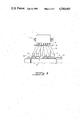
FIG. 4 shows the situation of readiness for refilling of the measuring chambers during the kneading process; and
FIG. 5 illustrates in principle the front view of FIGS. 1-4.
DESCRIPTION OF THE PREFERRED EMBODIMENT
The dough parting apparatus of the machine, in the illustrated exemplary embodiment, has a parting chamber roller 2 having individual parting chambers 3 and pivotably supported at 1 and 1' (see FIG. 5). A portion of the supply of dough located in a funnel 4 is filled by means of the main piston 5 into each of the individual chambers 3. Once the parting chambers 3 are filled, the parting chamber roller 2 is caused to pivot counterclockwise, as viewed in FIG. 1 whereupon the pieces of dough are expelled and scraped off from the parting piston 7 by means of the scraper shaft 6 which is likewise rotating counterclockwise that is, in the same direction as the counterclockwise movement of the parting chamber roller 2 (as viewed in FIG. 1). After the parting chamber roller 2 has reached its terminal pivoting position (FIG. 3), it is pivoted clockwise back into the refilling position (FIG. 4).
The channel apparatus 14 having an end 8 that is tubular in the lower portion is located beneath the dough parting apparatus. Beneath the end 8 is the kneading apparatus having the kneading cup carrier frame 9, in which the pre-kneading cups 10 and then the kneading cups 11 are fastened. The kneading belt 12 is located beneath these kneading cups.
The pre-kneading cups 10 and the kneading cups 11, together with the kneading cup carrier frame 9, are set into a spirally circling movement in a known manner. During the period when the kneading movement is executed, the kneading belt 12 is held stationary, so that the pieces of dough are round-kneaded in the pre-kneading cups 10 and the kneading cups 11.
During the period of round-kneading of the pieces of dough resting on the kneading belt, the filling process of the measuring chambers takes place. The measuring chambers 3 are filled with dough in that the main piston 5 presses the dough into the chambers. The parting pistons 7 are pushed back against the adjustable stop shaft 15 constituting a first stop means. By the pivoting of the parting chamber roller 2, the parting pistons 7 are brought into the expulsion position by means of the stop shaft 16 constituting a second stop means, which is disposed in a stationary manner (FIGS. 2 and 3), and which cooperates with a cam surface on the rear portion of the parting piston (as shown more clearly in FIG. 2). Thereafter, the scraper shaft 6 scrapes the portions of dough from the parting pistons 7 (FIG. 3).
Once the pre-kneading of the row of pieces of dough is completed, because of the prespecified duration of kneading, then as shown in FIG. 2 the kneading cup carrier frame 9 is raised, so that subsequently the kneading belt 12 advances the row of pieces of dough by an increment of one interval between rows in the direction of the arrow, that is, from the pre-kneading zone where the pre-kneading cups 10 are located into the kneading zone of the kneading cups 11.
While the kneading cup carrier frame 9 is raised from the kneading belt 12, no kneading movement takes place, and so the tubular lower ends 8 of the channel apparatus 14 enter into the pre-kneading cups 10 as these latter move upward (FIG. 2). During this period of time, the kneading belt 12 advances the row of dough pieces.
The kneading movement of the kneading cup carrier frame 9 is executed with known rotating eccentrics 13 and 13'; the axial zero position of the kneading eccentrics exists when the kneading eccentrics are moving upward.
The channel apparatus 14 receives the expelled pieces of dough at its upper end at predetermined intervals. The course of the channel in the channel apparatus 14 may be inclined, so that the tubular lower ends 8 may be spaced apart by a selectable distance, matching the transverse spacing between the pre-kneading cups 10. The channel apparatus 14 is easily interchangeable or adjustable for various transverse spacings, as is the receptacle for the pre-kneading cups 10 and the kneading cups 11, in terms of the transverse spacing between them.
Obviously, many modifications may be made without departing from the basic spirit of the present invention. Accordingly, within the scope of the appended claims, the invention may be practiced other than specifically disclosed herein.