US4580225A - Method for producing multiple entry threads - Google Patents
Method for producing multiple entry threads Download PDFInfo
- Publication number
- US4580225A US4580225A US06/534,793 US53479383A US4580225A US 4580225 A US4580225 A US 4580225A US 53479383 A US53479383 A US 53479383A US 4580225 A US4580225 A US 4580225A
- Authority
- US
- United States
- Prior art keywords
- thread
- workpiece
- cutting
- tool
- entry
- Prior art date
- Legal status (The legal status is an assumption and is not a legal conclusion. Google has not performed a legal analysis and makes no representation as to the accuracy of the status listed.)
- Expired - Fee Related
Links
Images


Classifications
-
- G—PHYSICS
- G05—CONTROLLING; REGULATING
- G05B—CONTROL OR REGULATING SYSTEMS IN GENERAL; FUNCTIONAL ELEMENTS OF SUCH SYSTEMS; MONITORING OR TESTING ARRANGEMENTS FOR SUCH SYSTEMS OR ELEMENTS
- G05B19/00—Program-control systems
- G05B19/02—Program-control systems electric
- G05B19/18—Numerical control [NC], i.e. automatically operating machines, in particular machine tools, e.g. in a manufacturing environment, so as to execute positioning, movement or co-ordinated operations by means of program data in numerical form
- G05B19/182—Numerical control [NC], i.e. automatically operating machines, in particular machine tools, e.g. in a manufacturing environment, so as to execute positioning, movement or co-ordinated operations by means of program data in numerical form characterised by the machine tool function, e.g. thread cutting, cam making, tool direction control
- G05B19/186—Generation of screw- or gearlike surfaces
-
- Y—GENERAL TAGGING OF NEW TECHNOLOGICAL DEVELOPMENTS; GENERAL TAGGING OF CROSS-SECTIONAL TECHNOLOGIES SPANNING OVER SEVERAL SECTIONS OF THE IPC; TECHNICAL SUBJECTS COVERED BY FORMER USPC CROSS-REFERENCE ART COLLECTIONS [XRACs] AND DIGESTS
- Y10—TECHNICAL SUBJECTS COVERED BY FORMER USPC
- Y10T—TECHNICAL SUBJECTS COVERED BY FORMER US CLASSIFICATION
- Y10T82/00—Turning
- Y10T82/20—Lathe for screw cutting
Definitions
- microfiche appendix forming a part of this application comprising one microfiche containing 31 frames.
- This invention relates to numerically controlled machine processes and, more particularly, to a method for numerically controlled machining of multiple entry threads.
- Multiple entry threads i.e., multiple parallel threads on a single shank with each thread having its own entry point at the end of the shank
- the mating part must also have multiple threads and requires a thread pitch equal to that of the multiple threads.
- Multiple entry threads have a number of applications, including their use to aid the quick replacement of automobile racing wheels.
- the conventional method for machining multiple entry threads is to initially produce a single thread and then to machine each additional thread by starting the cutting tool from a backed off position (along the threading axis) whose distance away from the thread entry point is proportional to the thread lead and inversely proportional to the number of threads to be cut.
- a double entry thread by the prior art method, an initial thread is cut, then the cutting tool is backed off from the initial entry point by one-half of the thread lead (thread lead is the distance between turns of the same thread). The backed off distance is thus added to the length of the threading path followed by the thread cutting tool.
- This method is effective because the speed at which the cutting tool is moved forward is directly related to the speed of the spindle which is turning the workpiece. As the workpiece rotates, the cutting tool advances to make contact at the desired entry point.
- This conventional method is more fully discussed herein below in connection with FIG. 1 and in contrast to the method of the present invention.
- a significant problem with the prior art method is that clearance is always required at the end of the workpiece to accommodate the backoff placement of the cutting tool. This accommodation cannot always be easily made.
- the principal object of the present invention to provide a method for producing multiple entry threads by which the need for tool backoff is eliminated; a method which may be implemented in a numerically controlled system in which the thread cutting tool starts from substantially the same position for each thread.
- This method produces multiple parallel threads on the workpiece and each pass of the cutting tool is started from the same position without the need for backoff clearance and the resulting wasted time and motion in traversing the backoff paths.
- FIG. 1 comprising FIGS. 1A-1C, is a schematic illustration of the prior art method for machining multiple entry threads on a workpiece
- FIG. 2 is a schematic illustration of a path followed by a tool cutting multiple entry threads according to the present invention
- FIG. 3 is a simplified schematic illustration of a numerically controlled lathe for machining multiple entry threads according to the invention
- FIG. 4 is a simplified partial block diagram of a computer numerical control system by which the present invention may be implemented
- FIG. 5 is a high level flow chart illustrating preferred steps for carrying out the present invention.
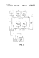
- FIG. 6 is a detailed flow chart illustrating the threading pass step of FIG. 5.
- FIGS. 1A-1C schematically illustrate the process for a triple entry thread, for example.
- These figures show a cutting tool 10 whose programmed, or otherwise controlled, path 12 is designed to produce the desired triple entry threads on the workpiece 14.
- the cutting tool path is illustrated by the arrowed lines 13, showing in each case, a generally rectangular pattern.
- the workpiece 14, during the thread cutting operation is being rotated at some uniform speed about an axis of rotation 16. Means for providing such rotation are not specifically illustrated.
- the cutting tool 10 starts at point A, advances inward toward the workpiece to point B, makes a threading move from point B to point C parallel to the axis of rotation 16, then is withdrawn from C to D, and is returned to the starting point A.
- the tool 10 For the second, parallel thread, (illustrated in FIG. 1B) the tool 10 must be backed off parallel to the axis of rotation 16 by a distance equal to one-third the thread lead length. The fraction one-third arises from the fact that three threads are to be cut. The backoff distance is thus shown as the distance A--A'. The cutting path for the second thread thus starts at point A', progressing to B', to C and back to A'.
- the tool is backed off by two-thirds of the lead length to start from A".
- the cutting tool 10 then follows the path from A" to B", to C, through D and then to a final position.
- FIGS. 1A-1C illustrate, in the prior art method, the backoff distance increases with each thread to be cut. It will, of course, be recognized, that for each thread, multiple cutting passes may be made in which tool 10 is advanced to make a slightly deeper cut on each pass in order to obtain the final thread depth and to compensate for tool deflection.
- the cutting tool 10 traverses an identical path for each thread. From a single starting point, the tool 10 makes as many cutting passes per thread as is required for the desired thread depth, including additional no load passes to correct for tool and part deflection. Multiple, parallel threads are made by keying the starting motion of the cutting tool (from the starting point) to an angular position of the workpiece. It will be recognized, however, that a cutting pass may also be made on each thread at one cutting depth before advancing the tool to the next cutting depth for again making cutting passes on all threads. The important point is that the cutting tool always starts from the same point so that there is no need for clearance to back the tool off nor is there any wasted movement of the tool.
- the tool 10 makes a first pass by moving from starting point A toward the workpiece 14 a distance equal to an offset distance X 1 plus the infeed distance X 2 .
- the workpiece is, of course, being rotated about an axis of rotation parallel with the Z axis so that a thread entry point for the first thread is produced at some angular position of the workpiece.
- the angular position of the workpiece at the first thread entry point may conveniently be referred to herein as the index angle.
- the tool is next moved parallel to the axis of rotation, following the path Z 1 for the length of the thread. At the end of the thread the tool may be pulled directly out of the thread or, as shown, may be pulled out at a slight taper to point B.
- the tool After the tool has pulled out from the thread, it then traverses back to the starting point A.
- the tool is preferably restarted along a path identical to the first pass just described but with the workpiece 14 in a different angular position so that the next thread entry point is separated from the first thread entry point by the desired angular separation.
- the tool 14 After a first pass on all threads, the tool 14 again starts from point A but plunges to a greater depth for the next pass, again passing along all threads at the same depth.
- the number of subsequent passes (illustrated as Z 2 , Z 3 , Z 4 , and Z 5 ) at the same depth as equal to the number of parallel threads.
- traversing moves of tool 10 such as along offset distance X 1
- Threading moves, however, such as along cutting path Z 1 are made with the speed of the cutting tool 10 proportional to the rotational speed of the workpiece 14.
- FIG. 3 is greatly simplified to facilitate an understanding of the invention, but, as is conventional, lathe 20 includes a chuck 24 which holds the workpiece 14 in one end while the opposite end is held against a centering mechanism 26 mounted on tailstock 28.
- the spindle drive motor (not specifically illustrated) mounted within spindle drive housing 21 rotates the chuck 24 and hence the workpiece 14 as it is mounted in the lathe.
- An angular position transducer 29 (e.g., a resolver or shaft encoder) is connected to the spindle drive and is driven thereby to provide a signal indicative of the instantaneous angular position of the spindle.
- a tool holding mechanism 30 carries a cutting tool 10 which is used, in this instance, for cutting threads on workpiece 14.
- the tool holding mechanism 30 includes conventional carriage means so that the cutting tool 10 can be moved in two dimensional directions, i.e., either in a direction parallel to the axis passing through the chuck 24 and centering mechanism 26, or perpendicular thereto.
- the cutting tool 10 may be moved parallel to the longitudinal axis of the workpiece 14 or it may be moved perpendicular thereto. It may at times be convenient herein to refer to the longitudinal axis of the workpiece as the Z axis and the axis perpendicular thereto as the X axis.
- the cutting tool 10 thus is movable in a plane parallel to the X Z plane.
- Controller 22 directs motion of the cutting tool 10 in accordance with a part program which may be supplied from a device such as a paper or magnetic tape reader 23, illustrated as part of the controller 22, but which may be a separate, external device. Alternatively, a part program may be entered through an operator keyboard on the control 22.
- part programs are divided into command blocks or work statements wherein each block of information within a part program defines a unidirectional movement of the machine cutting tool 30 with respect to the workpiece 14. There are certain moves, however, such as circular arcs or thread cutting cycles which are defined by "canned cycles" called by command blocks within the part programs.
- the part program would be such that cutting tool 10 is directed to cut a multiple entry thread on the workpiece using the method of the invention.
- the part program in such case provides the parameters for the multiple entry thread, providing, for example, information on the number of threads and the thread lead length.
- the program for implementing the essential steps of the method is resident in the controller 22.
- Computer numerical controller 22 may, for example, be a Mark Century® 2000 computer numerical control (CNC) available from General Electric Company. However, the method is applicable to other computer numerical control systems available from other manufacturers.
- CNC computer numerical control
- the Mark Century 2000 CNC is a microprocessor based control unit employing Intel 8086 and 8087 microprocessors.
- the hardware architecture for the Mark Century 2000 CNC is shown in FIG. 4.
- a system central processing unit (CPU) 46 performs processing operations for the system and contains the Intel 8086 and 8087 microprocessors.
- a system dynamic RAM 48 (Random Access Memory) contains read-write memory for the system and is coupled to the system CPU and other functional portions of the system through a system bus 50.
- An axis controller 52 connected to the bus provides several control functions for each driven axis of the machine tool.
- the axis controller contains its own microprocessor (not shown) which serves as a front end processor to interface a coordinated group of motion axes of the machine tool 60 to the system bus 50 while other processors within the controller 52 perform computations for the controlled axis.
- Machine tool 60 is a generalized representation of lathe 20 of FIG. 2.
- An input-output (I/O) controller 54 coordinates the system bus I/O operations and thus serves to connect the system bus 50 to a local I/O bus 56.
- the local I/O bus 56 connects the system to a non-volatile memory 58 in which the part programs and all system data which must be preserved are stored.
- the local I/O bus 56 also is connected to a local digital I/O 62 which is functionally associated with a machine control station 64.
- the local digital I/O 62 generates digitized actuator control signals for the machine tool 60 and provides feedback status data from the machine tool 60.
- NC control station 66 is also connected to the I/O controller 54.
- the NC control station 66 serves as a front panel to machine tool operators and part programmers.
- the machine control station 64 is a control panel from which the machine tool operator can perform manual operations and control the execution of the part programs. These control panels are generally illustrated as features of the NC control 22 of FIG. 3.
- the CNC illustrated in FIG. 4 operates under control of the system CPU 46 executing programs resident in the system RAM 48.
- Part programs may be input from an external device such as a paper tape cassette reader through the I/O controller 54 or the keyboard of the NC control station 66. Any part program which is input to the system is stored by the I/O controller 54 into non-volatile memory 58.
- the system CPU directs the execution of other part programs through the I/O controller 54 and the axis controller 52.
- Part programming axis commands are executed through the axis controller 52 which is connected to the machine tool 60, such as the lathe 20, illustrated in FIG. 3.
- the machine tool 60 contains axis feed drives which are under control of the axis controller 52.
- Non-axis commands are executed through the I/O controller 54, connected to the machine tool 60 through the local digital I/O bus 56. Commands entered with pushbuttons and controls on machine control station 64 are communicated to the I/O controller 54 and finally to the machine tool 60 through either the axis controller 52 or the local digital I/O bus 56.
- a CNC as with most other computer control systems, is evolved from a hardwired system into essentially a computer architecture which is customized into a firmware control system through the use of software.
- Computer programs i.e., software, provide the method for reconfiguring each of these computer systems into a system equivalent to those earlier hardwired systems.
- the method disclosed is thus configured in the form of a computer program which forces the hardware system illustrated in FIG. 4 to operate in a particular fashion in order to implement the improved method.
- FIG. 5 there is shown a high level flow chart which graphically illustrates a method according to the invention for machining multiple entry threads with a computer numerically controlled machine tool.
- the flow chart of FIG. 5 provides the basis for a software program which is operable on a CNC such as that of FIGS. 3 and 4.
- the program of the microfiche appendix hereto is a preferred form of such a program and was written for operation on a Mark Century 2000 control as has been described above.
- FIG. 5 there is an initial acceptance of a program block from a part program which, as mentioned above, may be stored on some storage media such as magnetic or paper tape.
- the part program specifies that multiple entry threads are to be cut and provides information such as the number of threads and the thread lead length.
- the following table includes the control words and parameters programmed for multiple pass, constant lead thread cutting sequences.
- the program is for a triangular cutting tool used in a plunge infeed cutting method wherein the incremental infeed of the tool on each cutting pass is controlled to remove an equal volume of metal.
- the computer numerical control uses resident application software, calculates the angular difference between thread entry points.
- This difference termed ⁇ , is determined simply by dividing 360° by M, the multiplicity of the number of threads to be cut. For example, for three threads the angular separation ⁇ is 120°.
- a cutting depth, or tool infeed distance is determined as indicated at box 79.
- the infeed distance on each cutting pass is such that an equal volume of metal is removed from the workpiece.
- the infeed distance for the first pass is specified by the part program and, then, on subsequent passes the initial infeed distance is simply multiplied by the square root of the pass number. For example, infeed distance of the tool on the second pass is ⁇ 2 times the initial infeed distance.
- a threading pass is directed at box 81.
- the threading pass at each infeed depth is repeated for each of the multiple threads until the particular cutting pass has been carried out for all threads. That is, a pass is made on all threads at the same cutting depth before an infeed movement of the cutting tool is made. This is implemented by the functional steps of boxes 83 and 85.
- the details of the threading pass, box 81, are more fully discussed herein below in connection with FIG. 6.
- step 79 for calculation of a new infeed distance which is then followed by implementation of cutting passes at the newly calculated depth. This process is reiterated until all threads are cut to the final depth as determined at box 87.
- step 90 data regarding all moves of the cutting tool for a given thread are generated. That is, the angle of the workpiece driving spindle for the thread entry point is generated along with distance and rate data for each movement of the cutting tool.
- the movement of the cutting tool is necessarily related to, or synchronized with, the speed of the spindle which is turning the workpiece.
- the object is merely to traverse some distance and the speed at which the tool is moved may be entirely independent of the spindle speed.
- the moves (threading or traversing) for that pass are provided in sequence (box 92) to the axis controller (as in FIG. 3, for example) to effect movement of the tool accordingly.
- each move is first tested in decision step 94 to determine if it is a threading move or a traversing move. If the move is a threading move for the particular pass being made, then step 96 is entered and the angle of the spindle for the entry point of the particular threading pass is provided to the spindle axis controller.
- the spindle axis controller controls and monitors the spindle drive, and may, for example, be part of the axis controller 52 of FIG. 4.
- step 98 is entered and the traversing move is executed immediately.
- a command is provided, box 100, to the axis controller to signal that the feed rate (i.e., the rate of tool movement relative to the workpiece) is to be proportional to the spindle speed and that any other feed rate commands are not to be followed.
- the angular position of the spindle is being continuously monitored, as by transducer 29 of FIG. 2, so that once the spindle is in the correct angular position as determined at decision box 102, the threading move data is passed and the move is executed as at step 98.
- the axis controller is inhibited at box 104 from effecting a movement of the tool and the angular position of the spindle continues to be monitored.
- step 106 the process is incremented at step 106 to produce the next move in the pass.
- Each move is tested at step 108 to determine if the pass is complete. If not, there is a return to step 92 to start the next move. The process is repeated until all moves of a pass are complete. There is then an increment to begin the next thread entry as shown at box 83 of FIG. 5.
Landscapes
- Engineering & Computer Science (AREA)
- Human Computer Interaction (AREA)
- Manufacturing & Machinery (AREA)
- Physics & Mathematics (AREA)
- General Physics & Mathematics (AREA)
- Automation & Control Theory (AREA)
- Numerical Control (AREA)
Abstract
Description
______________________________________
CONTROL WORD DESCRIPTION
______________________________________
G84          Plunge Threadcutting, Longitudinal
 X*          Absolute Coordinate of Thread Bottom
U            Total Thread Depth
 Z*          Absolute Coordinate to End of Thread
W            Thread Length
P.sub.1      Incremental Infeed Distance
P.sub.2      Thread Lead
P.sub.3      Taper Data
P.sub.4      Pull Out Data
P.sub.5      Number of Load Passes at Final Depth
P.sub.6      Number of Threads to be Cut
______________________________________
 *X or U; or Z or W alternately.
Claims (3)
Priority Applications (1)
| Application Number | Priority Date | Filing Date | Title |
|---|---|---|---|
| US06/534,793 US4580225A (en) | 1983-09-22 | 1983-09-22 | Method for producing multiple entry threads |
Applications Claiming Priority (1)
| Application Number | Priority Date | Filing Date | Title |
|---|---|---|---|
| US06/534,793 US4580225A (en) | 1983-09-22 | 1983-09-22 | Method for producing multiple entry threads |
Publications (1)
| Publication Number | Publication Date |
|---|---|
| US4580225A true US4580225A (en) | 1986-04-01 |
Family
ID=24131559
Family Applications (1)
| Application Number | Title | Priority Date | Filing Date |
|---|---|---|---|
| US06/534,793 Expired - Fee Related US4580225A (en) | 1983-09-22 | 1983-09-22 | Method for producing multiple entry threads |
Country Status (1)
| Country | Link |
|---|---|
| US (1) | US4580225A (en) |
Cited By (24)
| Publication number | Priority date | Publication date | Assignee | Title |
|---|---|---|---|---|
| US4703415A (en) * | 1983-10-15 | 1987-10-27 | Fanuc Ltd | Method of approach in area cutting |
| US4739489A (en) * | 1983-12-14 | 1988-04-19 | Fanuc Ltd. | Area cutting method |
| US4920830A (en) * | 1985-02-22 | 1990-05-01 | Jiri Stepan | Rotary wire stripper |
| US5144871A (en) * | 1989-12-08 | 1992-09-08 | Mitsubishi Denki K.K. | Numerically controlled screw cutting method for fine screw surface finishing |
| US5321346A (en) * | 1990-12-27 | 1994-06-14 | Fanuc Ltd. | NC data creation method |
| US6155148A (en) * | 1996-12-10 | 2000-12-05 | Fanuc Ltd. | Thread cutting method using lathe and numerical controller |
| US6176155B1 (en) | 1998-09-18 | 2001-01-23 | Schleuniger Holding Ag | Semi-automatic wire processing apparatus |
| EP2309355A1 (en) * | 2003-06-17 | 2011-04-13 | Kennametal Inc. | Uncoated cutting tool using brazed-in superhard blank |
| CN102601464A (en) * | 2011-12-21 | 2012-07-25 | 宁波方力科技股份有限公司 | Production method of extruder screw |
| US20150227129A1 (en) * | 2014-02-12 | 2015-08-13 | Fanuc Corporation | Numerical controller |
| KR101569173B1 (en) | 2007-08-13 | 2015-11-13 | 신세스 게엠바하 | high versatile variable-angle bone plate system |
| US9295505B2 (en) | 2003-08-26 | 2016-03-29 | DePuy Synthes Products, Inc. | Bone plate |
| US10231768B2 (en) | 2003-05-30 | 2019-03-19 | DePuy Synthes Products, Inc. | Methods for implanting bone plates |
| JP2019119016A (en) * | 2018-01-09 | 2019-07-22 | 株式会社ジェイテクト | Gear processor and gear processing method |
| US10624686B2 (en) | 2016-09-08 | 2020-04-21 | DePuy Synthes Products, Inc. | Variable angel bone plate |
| EP3523087A4 (en) * | 2016-10-06 | 2020-06-24 | Aktiebolaget Ledarskruv | MANUFACTURE OF SCREW RODS AND JOINT PRODUCTION AND MACHINE FOR THE MANUFACTURE THEREOF |
| US10772665B2 (en) | 2018-03-29 | 2020-09-15 | DePuy Synthes Products, Inc. | Locking structures for affixing bone anchors to a bone plate, and related systems and methods |
| US10820930B2 (en) | 2016-09-08 | 2020-11-03 | DePuy Synthes Products, Inc. | Variable angle bone plate |
| US10905476B2 (en) | 2016-09-08 | 2021-02-02 | DePuy Synthes Products, Inc. | Variable angle bone plate |
| US10925651B2 (en) | 2018-12-21 | 2021-02-23 | DePuy Synthes Products, Inc. | Implant having locking holes with collection cavity for shavings |
| US11013541B2 (en) | 2018-04-30 | 2021-05-25 | DePuy Synthes Products, Inc. | Threaded locking structures for affixing bone anchors to a bone plate, and related systems and methods |
| US11026727B2 (en) | 2018-03-20 | 2021-06-08 | DePuy Synthes Products, Inc. | Bone plate with form-fitting variable-angle locking hole |
| US11259851B2 (en) | 2003-08-26 | 2022-03-01 | DePuy Synthes Products, Inc. | Bone plate |
| US11291484B2 (en) | 2004-01-26 | 2022-04-05 | DePuy Synthes Products, Inc. | Highly-versatile variable-angle bone plate system |
Citations (6)
| Publication number | Priority date | Publication date | Assignee | Title |
|---|---|---|---|---|
| US3854353A (en) * | 1973-06-20 | 1974-12-17 | Bendix Corp | Method and apparatus for performing a threading operation on a rotating workpiece |
| US3949285A (en) * | 1974-10-15 | 1976-04-06 | The Superior Electric Company | Tapered thread numerical control system for a lathe |
| US4019035A (en) * | 1976-01-23 | 1977-04-19 | Cincinnati Milacron, Inc. | Method and apparatus for controlling the initiation of multiple start threading cuts |
| US4096770A (en) * | 1977-06-06 | 1978-06-27 | Cincinnati Milacron Inc. | Method and apparatus for modifying the position of a machine slide to compensate for different following errors |
| US4173786A (en) * | 1977-06-23 | 1979-11-06 | Cincinnati Milacron Inc. | Method and apparatus for cutting a thread on a rotating workpiece |
| US4250551A (en) * | 1979-07-11 | 1981-02-10 | Giddings & Lewis, Inc. | Methods and apparatus for lead segment machining |
-
1983
- 1983-09-22 US US06/534,793 patent/US4580225A/en not_active Expired - Fee Related
Patent Citations (6)
| Publication number | Priority date | Publication date | Assignee | Title |
|---|---|---|---|---|
| US3854353A (en) * | 1973-06-20 | 1974-12-17 | Bendix Corp | Method and apparatus for performing a threading operation on a rotating workpiece |
| US3949285A (en) * | 1974-10-15 | 1976-04-06 | The Superior Electric Company | Tapered thread numerical control system for a lathe |
| US4019035A (en) * | 1976-01-23 | 1977-04-19 | Cincinnati Milacron, Inc. | Method and apparatus for controlling the initiation of multiple start threading cuts |
| US4096770A (en) * | 1977-06-06 | 1978-06-27 | Cincinnati Milacron Inc. | Method and apparatus for modifying the position of a machine slide to compensate for different following errors |
| US4173786A (en) * | 1977-06-23 | 1979-11-06 | Cincinnati Milacron Inc. | Method and apparatus for cutting a thread on a rotating workpiece |
| US4250551A (en) * | 1979-07-11 | 1981-02-10 | Giddings & Lewis, Inc. | Methods and apparatus for lead segment machining |
Cited By (31)
| Publication number | Priority date | Publication date | Assignee | Title |
|---|---|---|---|---|
| US4703415A (en) * | 1983-10-15 | 1987-10-27 | Fanuc Ltd | Method of approach in area cutting |
| US4739489A (en) * | 1983-12-14 | 1988-04-19 | Fanuc Ltd. | Area cutting method |
| US4920830A (en) * | 1985-02-22 | 1990-05-01 | Jiri Stepan | Rotary wire stripper |
| US5144871A (en) * | 1989-12-08 | 1992-09-08 | Mitsubishi Denki K.K. | Numerically controlled screw cutting method for fine screw surface finishing |
| US5321346A (en) * | 1990-12-27 | 1994-06-14 | Fanuc Ltd. | NC data creation method |
| US6155148A (en) * | 1996-12-10 | 2000-12-05 | Fanuc Ltd. | Thread cutting method using lathe and numerical controller |
| US6176155B1 (en) | 1998-09-18 | 2001-01-23 | Schleuniger Holding Ag | Semi-automatic wire processing apparatus |
| US10231768B2 (en) | 2003-05-30 | 2019-03-19 | DePuy Synthes Products, Inc. | Methods for implanting bone plates |
| US11419647B2 (en) | 2003-05-30 | 2022-08-23 | DePuy Synthes Products, Inc. | Bone plate |
| US10653466B2 (en) | 2003-05-30 | 2020-05-19 | DePuy Synthes Products, Inc. | Bone plate |
| EP2309355A1 (en) * | 2003-06-17 | 2011-04-13 | Kennametal Inc. | Uncoated cutting tool using brazed-in superhard blank |
| US11259851B2 (en) | 2003-08-26 | 2022-03-01 | DePuy Synthes Products, Inc. | Bone plate |
| US9295505B2 (en) | 2003-08-26 | 2016-03-29 | DePuy Synthes Products, Inc. | Bone plate |
| US10342586B2 (en) | 2003-08-26 | 2019-07-09 | DePuy Synthes Products, Inc. | Bone plate |
| US9314284B2 (en) | 2004-01-26 | 2016-04-19 | DePuy Synthes Products, Inc. | Highly-versatile variable-angle bone plate system |
| US10335211B2 (en) | 2004-01-26 | 2019-07-02 | DePuy Synthes Products, Inc. | Highly-versatile variable-angle bone plate system |
| US11291484B2 (en) | 2004-01-26 | 2022-04-05 | DePuy Synthes Products, Inc. | Highly-versatile variable-angle bone plate system |
| KR101569173B1 (en) | 2007-08-13 | 2015-11-13 | 신세스 게엠바하 | high versatile variable-angle bone plate system |
| CN102601464A (en) * | 2011-12-21 | 2012-07-25 | 宁波方力科技股份有限公司 | Production method of extruder screw |
| US20150227129A1 (en) * | 2014-02-12 | 2015-08-13 | Fanuc Corporation | Numerical controller |
| US9869989B2 (en) * | 2014-02-12 | 2018-01-16 | Fanuc Corporation | Numerical controller |
| US11529176B2 (en) | 2016-09-08 | 2022-12-20 | DePuy Synthes Products, Inc. | Variable angle bone plate |
| US10820930B2 (en) | 2016-09-08 | 2020-11-03 | DePuy Synthes Products, Inc. | Variable angle bone plate |
| US10905476B2 (en) | 2016-09-08 | 2021-02-02 | DePuy Synthes Products, Inc. | Variable angle bone plate |
| US10624686B2 (en) | 2016-09-08 | 2020-04-21 | DePuy Synthes Products, Inc. | Variable angel bone plate |
| EP3523087A4 (en) * | 2016-10-06 | 2020-06-24 | Aktiebolaget Ledarskruv | MANUFACTURE OF SCREW RODS AND JOINT PRODUCTION AND MACHINE FOR THE MANUFACTURE THEREOF |
| JP2019119016A (en) * | 2018-01-09 | 2019-07-22 | 株式会社ジェイテクト | Gear processor and gear processing method |
| US11026727B2 (en) | 2018-03-20 | 2021-06-08 | DePuy Synthes Products, Inc. | Bone plate with form-fitting variable-angle locking hole |
| US10772665B2 (en) | 2018-03-29 | 2020-09-15 | DePuy Synthes Products, Inc. | Locking structures for affixing bone anchors to a bone plate, and related systems and methods |
| US11013541B2 (en) | 2018-04-30 | 2021-05-25 | DePuy Synthes Products, Inc. | Threaded locking structures for affixing bone anchors to a bone plate, and related systems and methods |
| US10925651B2 (en) | 2018-12-21 | 2021-02-23 | DePuy Synthes Products, Inc. | Implant having locking holes with collection cavity for shavings |
Similar Documents
| Publication | Publication Date | Title |
|---|---|---|
| US4580225A (en) | Method for producing multiple entry threads | |
| DE69032694T2 (en) | DYNAMIC ERROR IMPROVEMENT CAUSED BY THE SERVOMECHANISM IN A NUMERICALLY CONTROLLED COMPUTER SYSTEM AND ITS USE IN A CONTINUOUS CYCLE | |
| US3854353A (en) | Method and apparatus for performing a threading operation on a rotating workpiece | |
| DE3785827T2 (en) | SYSTEM FOR REGULATING THE PIN. | |
| KR850000325B1 (en) | Numerical control method | |
| US4963805A (en) | Numerical control apparatus for machining non-circular workpieces | |
| CA2231308C (en) | Adaptive feedrates from geometry modeling for nc machining | |
| DE3886138T2 (en) | Numerically controlled machine tool. | |
| US4757457A (en) | Numerical control method and apparatus with feedrate difference | |
| US4173786A (en) | Method and apparatus for cutting a thread on a rotating workpiece | |
| JPH1190774A5 (en) | ||
| EP0103198A2 (en) | A method for interrupting machine operation in a CNC system | |
| EP0104542B1 (en) | Numerically controlled machining method | |
| Madison | CNC machining handbook: basic theory, production data, and machining procedures | |
| US4386407A (en) | Lathe control system | |
| JPS62237504A (en) | Numerical controller | |
| WO1988010171A1 (en) | Acceleration/deceleration controller | |
| US11402822B2 (en) | Numerical controller | |
| US4698573A (en) | Numerically controlled working process | |
| JPH02311218A (en) | Tapping method | |
| US4514611A (en) | Method of controlling electric discharge machine | |
| US5237251A (en) | Control unit for a machine with a tapping function | |
| EP0301097B1 (en) | Method of numerical control | |
| US4644124A (en) | Wire electrode type electrical discharge machining method | |
| EP0362391A1 (en) | Involute interpolating method |
Legal Events
| Date | Code | Title | Description |
|---|---|---|---|
| AS | Assignment |
Owner name: GENERAL ELECTRIC COMPANY A NY CORP Free format text: ASSIGNMENT OF ASSIGNORS INTEREST.;ASSIGNOR:THOMPSON, WALTER L.;REEL/FRAME:004178/0805 Effective date: 19830919 Owner name: GENERAL ELECTRIC COMPANY A NY CORP, NEW YORK Free format text: ASSIGNMENT OF ASSIGNORS INTEREST;ASSIGNOR:THOMPSON, WALTER L.;REEL/FRAME:004178/0805 Effective date: 19830919 |
|
| FEPP | Fee payment procedure |
Free format text: PAYER NUMBER DE-ASSIGNED (ORIGINAL EVENT CODE: RMPN); ENTITY STATUS OF PATENT OWNER: LARGE ENTITY Free format text: PAYOR NUMBER ASSIGNED (ORIGINAL EVENT CODE: ASPN); ENTITY STATUS OF PATENT OWNER: LARGE ENTITY |
|
| AS | Assignment |
Owner name: GENERAL ELECTRIC COMPANY, A CORP. OF NY Free format text: AGREEMENT;ASSIGNORS:GENERAL ELECTRIC COMPANY;GE FANUC AUTOMATION NORTH AMERICA, INC.;REEL/FRAME:005004/0718 Effective date: 19880101 Owner name: GE FAUNC AUTOMATION NORTH AMERICA, A CORP. OF DE Free format text: AGREEMENT;ASSIGNORS:GENERAL ELECTRIC COMPANY;GE FANUC AUTOMATION NORTH AMERICA, INC.;REEL/FRAME:005004/0718 Effective date: 19880101 |
|
| FPAY | Fee payment |
Year of fee payment: 4 |
|
| REMI | Maintenance fee reminder mailed | ||
| LAPS | Lapse for failure to pay maintenance fees | ||
| FP | Lapsed due to failure to pay maintenance fee |
Effective date: 19900403 |
|
| STCH | Information on status: patent discontinuation |
Free format text: PATENT EXPIRED DUE TO NONPAYMENT OF MAINTENANCE FEES UNDER 37 CFR 1.362 |