US4576391A - Rollable pallet assembly and caster device - Google Patents
Rollable pallet assembly and caster device Download PDFInfo
- Publication number
- US4576391A US4576391A US06/513,811 US51381183A US4576391A US 4576391 A US4576391 A US 4576391A US 51381183 A US51381183 A US 51381183A US 4576391 A US4576391 A US 4576391A
- Authority
- US
- United States
- Prior art keywords
- plate
- pallet
- caster
- extending
- secured
- Prior art date
- Legal status (The legal status is an assumption and is not a legal conclusion. Google has not performed a legal analysis and makes no representation as to the accuracy of the status listed.)
- Expired - Fee Related
Links
- 239000011800 void material Substances 0.000 claims 1
- 238000004873 anchoring Methods 0.000 abstract description 2
- 239000000463 material Substances 0.000 description 3
- XEEYBQQBJWHFJM-UHFFFAOYSA-N Iron Chemical compound [Fe] XEEYBQQBJWHFJM-UHFFFAOYSA-N 0.000 description 2
- 238000007792 addition Methods 0.000 description 2
- 230000004075 alteration Effects 0.000 description 2
- 238000000034 method Methods 0.000 description 2
- 238000012986 modification Methods 0.000 description 2
- 230000004048 modification Effects 0.000 description 2
- 238000010079 rubber tapping Methods 0.000 description 2
- 239000004677 Nylon Substances 0.000 description 1
- 229910000831 Steel Inorganic materials 0.000 description 1
- 229910052742 iron Inorganic materials 0.000 description 1
- 229920001778 nylon Polymers 0.000 description 1
- 239000004033 plastic Substances 0.000 description 1
- 229920003023 plastic Polymers 0.000 description 1
- 229920002635 polyurethane Polymers 0.000 description 1
- 239000004814 polyurethane Substances 0.000 description 1
- 239000012858 resilient material Substances 0.000 description 1
- 239000010959 steel Substances 0.000 description 1
- 239000002023 wood Substances 0.000 description 1
Images

Classifications
-
- B—PERFORMING OPERATIONS; TRANSPORTING
- B60—VEHICLES IN GENERAL
- B60B—VEHICLE WHEELS; CASTORS; AXLES FOR WHEELS OR CASTORS; INCREASING WHEEL ADHESION
- B60B33/00—Castors in general; Anti-clogging castors
- B60B33/0002—Castors in general; Anti-clogging castors assembling to the object, e.g. furniture
-
- B—PERFORMING OPERATIONS; TRANSPORTING
- B62—LAND VEHICLES FOR TRAVELLING OTHERWISE THAN ON RAILS
- B62B—HAND-PROPELLED VEHICLES, e.g. HAND CARTS OR PERAMBULATORS; SLEDGES
- B62B5/00—Accessories or details specially adapted for hand carts
- B62B5/0083—Wheeled supports connected to the transported object
-
- B—PERFORMING OPERATIONS; TRANSPORTING
- B65—CONVEYING; PACKING; STORING; HANDLING THIN OR FILAMENTARY MATERIAL
- B65D—CONTAINERS FOR STORAGE OR TRANSPORT OF ARTICLES OR MATERIALS, e.g. BAGS, BARRELS, BOTTLES, BOXES, CANS, CARTONS, CRATES, DRUMS, JARS, TANKS, HOPPERS, FORWARDING CONTAINERS; ACCESSORIES, CLOSURES, OR FITTINGS THEREFOR; PACKAGING ELEMENTS; PACKAGES
- B65D19/00—Pallets or like platforms, with or without side walls, for supporting loads to be lifted or lowered
- B65D19/38—Details or accessories
- B65D19/40—Elements for spacing platforms from supporting surface
- B65D19/42—Arrangements or applications of rollers or wheels
Definitions
- the present invention generally relates to loading pallets and more particularly to improved pallets bearing readily removable caster devices of an improved type.
- Conventional wooden pallets are used for storage of various items and normally do not include wheels or other means for moving them. When it is desired to move them, they must be picked up, by hand or by a fork-lift truck or the like and hauled by the truck or placed on a wheeled dolly or truck for hauling, such as is shown, for example, in U.S. Pat. No. 4,077,644, in U.S. Pat. No, 3,001,797, and in U.S. Pat. No. 3,058,770. These procedures take considerable time and effort and require the use of various types of equipment.
- Each such device includes a rotatable caster secured by a bracket to the underside of a horizontal plate. Another horizontal plate is held in spaced relation thereto by a vertical web at one end of the plates.
- a pocket or sleeve is formed thereby in which an edge, such as a corner, of the pallet is held by anchoring means such as sharpened nuts which with associated bolts connect the caster bracket to the lower plate.
- anchoring means such as sharpened nuts which with associated bolts connect the caster bracket to the lower plate.
- the plates and/or web may also bear spiked surfaces for the same purpose.
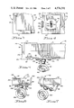
- FIG. 1 is a schematic fragmentary side elevation, party broken away, of a first preferred embodiment of the improved pallet assembly of the present invention.
- FIG. 2 is a schematic fragmentary side elevation, partly broken away, of a second preferred embodiment of the improved pallet assembly of the present invention.
- FIG. 6 is a schematic, fragmentary side elevation of a fifth preferred embodiment of the improved pallet assembly of the present invention.
- the components of device 14 can be made of various conventional inexpensive materials, such as steel or iron or the like (plates 16 and 18, web 20 and bracket 26) for durability and ease of use.
- FIG. 5 A fourth preferred embodiment of the improved pallet assembly of the present invention is schematically depicted in FIG. 5. Components thereof similar to those of any of FIGS. 1 through 4 bear the same numerals but are succeeded by the letter "c".
- assembly 10c is shown which includes pallet 12c and a plurality of devices 14c.
- Each device 14c includes plate 16c, web 20c and plate 18c.
- web 20c slideably receives a depending leg 58 of plate 16c and in turn includes a lower horizontal portion 60 which slideably receives plate 18c and which bears flange 46c.
- the height of wheel 44c is adjustable because socket 38c comprises two telescoping portions 62 and 64 releasably and adjustably secured together by screw 66, as shown in FIG. 5.
- device 14c is readily adaptable to various pallets 12c and allows a maximum of adjustability in a simple effective manner.
- Bracket 26d bears caster wheel 44d.
- Plate 18d is of sufficient length to span and embrace the width of board 12d and includes an upturned end 66, as shown in FIG. 6, which end 66 abuts pallet 12d and terminates with flange 46d.
- End 66 can be made of resilient material thereto, so that it tightly grips pallet 12d but so that device 14d still can be removed from pallet 12d by tapping on flange 46d with a hammer in the direction of the arrow shown in FIG. 6.
- Device 14d has substantially the advantages of devices 14, 14a, 14b and 14c and can be fabricated of similar materials.
- FIG. 7 shows a method by which device 14d can be secured to a pallet.
- the board 12d of a pallet can be raised off the ground, as by a fork-lift truck, and which raised, the device 14d can be placed partially over board 12d.
- device 14d is automatically forced and rotated into the position shown in FIG. 6, with spiked nut 34d retaining device 14d in place.
Landscapes
- Engineering & Computer Science (AREA)
- Mechanical Engineering (AREA)
- Chemical & Material Sciences (AREA)
- Combustion & Propulsion (AREA)
- Transportation (AREA)
- Pallets (AREA)
Abstract
The assembly comprises a flat pallet of extended surface area and a plurality of knock-off caster devices of improved type releasably secured to the pallet. Each caster device includes upper and lower horizontal plates joined at one end by a vertical web to form a sleeve in which an edge or end of the pallet is releasably secured by anchoring spikes, nuts or the like. A caster bracket is secured to the underside of the lower plate and a rotatable caster depends therefrom. A flange, detent or the like is provided to facilitate knock-off of the caster device from the pallet when the device is no longer needed. Preferably, the caster device is adjustable in plate length, sleeve height and/or caster position. The device may include a type which has a pair of casters, brackets and sleeves on opposite ends of the lower plate, which is adjustable to span the pallet. In a second type, the lower plate spans the pallet and has an upturned end abutting the pallet end and bearing a flange. In another embodiment, the device is configured and dimensioned such that the sleeve receives a whole corner of the pallet. Each caster device is inexpensive, durable, efficient and easy to install on and remove from the pallet.
Description
1. Field of the Invention
The present invention generally relates to loading pallets and more particularly to improved pallets bearing readily removable caster devices of an improved type.
2. Prior Art
Conventional wooden pallets are used for storage of various items and normally do not include wheels or other means for moving them. When it is desired to move them, they must be picked up, by hand or by a fork-lift truck or the like and hauled by the truck or placed on a wheeled dolly or truck for hauling, such as is shown, for example, in U.S. Pat. No. 4,077,644, in U.S. Pat. No, 3,001,797, and in U.S. Pat. No. 3,058,770. These procedures take considerable time and effort and require the use of various types of equipment.
Accordingly, there is a need for an improved inexpensive type of loading pallet which can be easily maneuvered with a minimum amount of effort from one location to another, and without the use of a dolly, fork-lift truck or the like and which can also be easily and compactly stored.
The improved rollable pallet assembly and caster device of the present invention satisfy the foregoing needs. The assembly and device are substantially as set forth in the Abstract above. Thus, the assembly has a flat pallet to which are removably affixed a plurality of spaced, knock-off caster devices. The devices are rapidly and easily installed on the pallet for transportation of the pallet and are just as easily and rapidly removed from the pallet when it is desired to store the pallet.
Each such device includes a rotatable caster secured by a bracket to the underside of a horizontal plate. Another horizontal plate is held in spaced relation thereto by a vertical web at one end of the plates.
A pocket or sleeve is formed thereby in which an edge, such as a corner, of the pallet is held by anchoring means such as sharpened nuts which with associated bolts connect the caster bracket to the lower plate. The plates and/or web may also bear spiked surfaces for the same purpose.
A flange, knob, detent or the like may be provided on one of the plates to facilitate knocking the caster device from the pallet. The device may be adjustable in plate length, caster height and/or sleeve depth. Moreover, it can be designed to cover on entire corner of the pallet or to span the pallet so as to provide a caster and sleeve at one or both of the opposite ends of the pallet. The device is simple, inexpensive, light in weight, durable and efficient. Other features of the invention are set forth in the following detailed description and accompanying drawings.
FIG. 1 is a schematic fragmentary side elevation, party broken away, of a first preferred embodiment of the improved pallet assembly of the present invention.
FIG. 2 is a schematic fragmentary side elevation, partly broken away, of a second preferred embodiment of the improved pallet assembly of the present invention.
FIG. 3 is a schematic, fragmentary top plan view of a third preferred embodiment of the improved pallet assembly of the present invention.
FIG. 4 is a schematic, fragmentary bottom plan view of the embodiment of FIG. 3.
FIG. 5 is a schematic, fragmentary side elevation, partly broken away, of a fourth preferred embodiment of the improved pallet assembly of the present invention.
FIG. 6 is a schematic, fragmentary side elevation of a fifth preferred embodiment of the improved pallet assembly of the present invention.
FIG. 7 is a schematic of the assembly of FIG. 6, prior to attachment to the pallet.
Now referring more particularly to FIG. 1 of the accompanying drawings, a first preferred embodiment of the pallet assembly of the invention is schematically depicted therein. Thus, assembly 10 is shown which comprises a flat pallet 12 of wood, plastic or the like which is of extended surface area. A spaced pair of improved caster devices 14 are releasably connected to pallet 12. Each device 14 comprises a short, upper horizontal plate 16, a longer lower horizontal plate 18, and a vertical wall or web 20 interconnecting one end of plates 16 and 18 to form a sleeve 22 having a space of, for example, a depth of about 1 inch, within which an edge or end 24 of pallet 12 is disposed.
A bracket 26 is secured to the underside of plate 18 by bolts 28 and 30 bearing nuts 32 and 34, respectively. It will be noted that nut 34 has a pointed top 36 adapted to engage pallet 12 to help anchor device 14 in place on pallet 12. Bracket 26 includes a depending tubular socket 38 to which is rotatably secured a depending shaft 40 also secured to the hub 42 of a caster wheel 44 of nylon, polyurethane or the like. Wheel 44 rotates freely 360° with a shaft 40.
The components of device 14 can be made of various conventional inexpensive materials, such as steel or iron or the like ( plates 16 and 18, web 20 and bracket 26) for durability and ease of use.
A second preferred embodiment of the improved pallet assembly of the present invention is schematically depicted in FIG. 2. Components similar to those of FIG. 1 bear the same numerals but are succeeded by the letter "a". Thus, assembly 10a is shown which includes pallet 12a bridged by device 14a which comprises a pair of sleeves 20 formed of upper plates 16a, webs 20a and lower plates 18a, the latter slideably interconnected and releasably secured by a key 50. Plates 18a span pallet 12a and bear a pair of brackets 26a and wheels 44a at opposite ends thereof. Spikes 52 protrude from the inner surfaces of webs 20a into pallet 12a, releasably securing device 14a in place on pallet 12a, while flanges 46a are provided for easy knock-off removal of device 14a from pallet 12a after key 50 is loosened so that plates 18a can be slid apart. Thus, device 14a serves the purpose of and is quite similar to a pair of devices 14. Moreover, device 14a is easily adaptable to pallets 12a of various lengths and widths.
Now referring to FIGS. 3 and 4 of the accompanying drawings, a third preferred embodiment of the improved pallet assembly of the present invention is schematically depicted therein. Components thereof similar to those of FIGS. 1 or 2 bear the same numerals but are succeeded by the letter "b". Thus, assembly 10b is shown which comprises a flat pallet 12b and four caster devices 14b and of which is shown in FIGS. 3 and 4. Each device 14b is designed to cover a corner of pallet 12a. Thus, plate 16b is shown in an L-shaped configuration, while plate 18b is rectangular. Web 20b joins plates 16b and 18b at their outer edges to form sleeve 22b in which the entire corner of pallet 12b is inserted. Web 20b has spikes 52b protruding into pallet 12b to hold device 14b thereto. Bracket 26b is secured to plate 18b by four rivets 56 and wheel 44b is centered on bracket 26b by socket 38b and shaft 40b. Device 14b function similarly to device 14a, which has the same advantages and can be fabricated of similar materials.
A fourth preferred embodiment of the improved pallet assembly of the present invention is schematically depicted in FIG. 5. Components thereof similar to those of any of FIGS. 1 through 4 bear the same numerals but are succeeded by the letter "c". Thus, assembly 10c is shown which includes pallet 12c and a plurality of devices 14c. Each device 14c includes plate 16c, web 20c and plate 18c. However, web 20c slideably receives a depending leg 58 of plate 16c and in turn includes a lower horizontal portion 60 which slideably receives plate 18c and which bears flange 46c. Thus, sleeve 22c is adjustable in depth to accommodate various thicknesses of pallet 12c and device 14c is adjustable in effective length of plate 18c so as to permit wheel 44c to be positioned advantageously at various locations with respect to pallet 12c. Spikes 52c protrude from portion 60 and plate 18c to releasable anchor device 14 to pallet 12c.
Moreover, the height of wheel 44c is adjustable because socket 38c comprises two telescoping portions 62 and 64 releasably and adjustably secured together by screw 66, as shown in FIG. 5. Thus, device 14c is readily adaptable to various pallets 12c and allows a maximum of adjustability in a simple effective manner.
A fifth preferred embodiment of the improved pallet assembly of the present invention is schematically depicted in FIG. 6. Components thereof similar to those of any of FIGS. 1 through 5 bear the same numerals but are succeeded by the letter "d". This embodiment would have particular application to pallets made from a plurality of boards extending at right angles to one another forming an open web pattern. The assembly 10d would be secured at one or more corners of such a slab so as to traverse the width of one of said board. Thus, assembly 10d is shown which includes pallet 12d and device 14d. Device 14d includes plates 16d and 18d interconnected by web 20d. Bracket 26d is secured to plate 18d by bolts 30d bearing spiked nuts 34d to hold device 14d in place. Bracket 26d bears caster wheel 44d. Plate 18d is of sufficient length to span and embrace the width of board 12d and includes an upturned end 66, as shown in FIG. 6, which end 66 abuts pallet 12d and terminates with flange 46d. End 66 can be made of resilient material thereto, so that it tightly grips pallet 12d but so that device 14d still can be removed from pallet 12d by tapping on flange 46d with a hammer in the direction of the arrow shown in FIG. 6. Device 14d has substantially the advantages of devices 14, 14a, 14b and 14c and can be fabricated of similar materials.
FIG. 7 shows a method by which device 14d can be secured to a pallet. The board 12d of a pallet can be raised off the ground, as by a fork-lift truck, and which raised, the device 14d can be placed partially over board 12d. As the board 12d is then lowered to the ground, device 14d is automatically forced and rotated into the position shown in FIG. 6, with spiked nut 34d retaining device 14d in place.
Various other modifications, changes, alterations and additions can be made in the improved rollable pallet assembly of the present invention, its components, including the novel caster device of the present invention and the parameters thereof. All such modifications changes, alterations and additions as are within the scope of the appended claims form part of the present invention.
Claims (4)
1. An improved knock-off caster device for a pallet, said device comprising, in combination:
(a) an upper generally horizontal plate,
(b) a lower generally horizontal plate,
(c) a first generally vertical web interconnecting said plates at one end thereof,
(d) a second generally vertically extending plate connected to the opposite end of said lower plate, and extending to an upper terminus, said upper terminus being free from any structure which extends toward said upper plate, said second plate lying opposite said web and extending upwardly from said lower plate in a first plane,
(e) said upper plate having a length substantially shorter than the length of said lower plate to thereby define an opening extending between the opposite end of said upper plate and said first plane, whereby a member of said pallet can be inserted through said opening and into the cavity formed by said plates and web,
(f) a caster bracket connected to the underside of said second plate, and
(g) a caster rotatably secured to and depending from said bracket.
2. A caster assembly for a pallet comprising:
(a) a horizontal base plate,
(b) a first upwardly extending plate connected at its lower end to one end of said base plate,
(c) a second upwardly extending plate lying substantially within a single plane, connected at its lower end to the opposite end of said base plate and extending to an upper terminus, said upper terminus being free from any structure which extends toward said upper plate,
(d) a third plate extending horizontally and substantially parallel to said base plate,
(e) said third plate being connected at one end thereof to the upper end of said first upwardly extending plate,
(f) said base plate having a length significantly greater than said third plate, such that a void space is provided in the area between one end of said third plate and said single plane,
(g) said plates defining a cavity adapted to receive and retain a board on a pallet,
(h) a caster bracket secured to the underside of said first plate, and
(i) a caster secured to said caster bracket.
3. An improved knock-off caster device for a pallet, said device comprising, in combination:
(a) an upper generally horizontal plate,
(b) a lower generally horizontal plate,
(c) a first generally vertical web interconnecting said plates at one end thereof,
(d) a second generally vertically extending plate connected to the opposite end of said lower plate, said second plate lying opposite said web and extending upwardly from said lower plate,
(e) said upper plate having a length substantially shorter than the length of said lower plate, whereby a member of said pallet can be inserted into the cavity formed by said plates and web,
(f) a caster bracket connected to the underside of said second plate,
(g) a caster rotatably secured to and depending from said bracket,
(h) wherein said device includes a flange adapted to be struck to facilitate knocking off said device from a pallet, and
(i) wherein said flange is secured to the top of said second vertically extending plate.
4. The caster device of claim 3 wherein said second vertical plate is resilient.
Priority Applications (1)
| Application Number | Priority Date | Filing Date | Title |
|---|---|---|---|
| US06/513,811 US4576391A (en) | 1983-07-15 | 1983-07-15 | Rollable pallet assembly and caster device |
Applications Claiming Priority (1)
| Application Number | Priority Date | Filing Date | Title |
|---|---|---|---|
| US06/513,811 US4576391A (en) | 1983-07-15 | 1983-07-15 | Rollable pallet assembly and caster device |
Publications (1)
| Publication Number | Publication Date |
|---|---|
| US4576391A true US4576391A (en) | 1986-03-18 |
Family
ID=24044764
Family Applications (1)
| Application Number | Title | Priority Date | Filing Date |
|---|---|---|---|
| US06/513,811 Expired - Fee Related US4576391A (en) | 1983-07-15 | 1983-07-15 | Rollable pallet assembly and caster device |
Country Status (1)
| Country | Link |
|---|---|
| US (1) | US4576391A (en) |
Cited By (31)
| Publication number | Priority date | Publication date | Assignee | Title |
|---|---|---|---|---|
| USD363209S (en) | 1994-10-07 | 1995-10-17 | Murphy Thomas V | Attachable caster unit |
| US5503417A (en) * | 1994-10-07 | 1996-04-02 | Murphy; Thomas V. | Erectable display assembly with casters |
| AT1827U1 (en) * | 1997-01-09 | 1997-12-29 | Geschuetzte Werkstaette St Poe | TRANSPORT AID FOR WOODEN PALLETS |
| AT1828U1 (en) * | 1997-02-27 | 1997-12-29 | Ameisbichler Rudolf | ROLE FOR ATTACHING TO A PALLET |
| US5934639A (en) * | 1996-07-12 | 1999-08-10 | John Gusdorf And Associates, Ltd. | Universal bracket for caster attachment to wire fabricated components |
| DE10002210A1 (en) * | 2000-01-19 | 2001-07-26 | Ludwig Gebhardt Gmbh & Co Betr | Transport device |
| US6450515B1 (en) | 2000-10-10 | 2002-09-17 | James F. Guth | Clip-on wheels for pallets or other structures with runners |
| US20030151231A1 (en) * | 2000-11-21 | 2003-08-14 | Calleja Michael J. | Foldable pallet-cart |
| EP1526058A1 (en) * | 2003-10-21 | 2005-04-27 | Getrag Ford Transmissions GmbH | Transport trolley |
| US6955368B2 (en) * | 2002-09-10 | 2005-10-18 | Bakhoum Ezzat G | Quick assembly, minimal effort carriage for moving heavy objects |
| US20060071438A1 (en) * | 2002-09-10 | 2006-04-06 | Bakhoum Ezzat G | Quick assembly, minimal effort carriage for moving heavy objects |
| US20060075600A1 (en) * | 2004-10-12 | 2006-04-13 | Dominic Dennis P | Vertically adjustable caster |
| US20060103092A1 (en) * | 2004-03-11 | 2006-05-18 | Mark Strahler | Universal mobile base |
| GB2422364A (en) * | 2004-12-03 | 2006-07-26 | Ds Smith | Paperboard dolly with detachable castors |
| EP1666330A3 (en) * | 2004-12-03 | 2007-11-14 | Besin B.V. | Mobile platform |
| EP1886841A1 (en) * | 2006-06-16 | 2008-02-13 | Kwang Yang Motor Co., Ltd. | Wheel device for a frame |
| US20080308359A1 (en) * | 2007-06-15 | 2008-12-18 | Waltz Lucas B | Quick change load wheel assembly |
| US20090056070A1 (en) * | 2007-08-30 | 2009-03-05 | James Jeffrey R | Adapter for mounting caster on height-adjustable leg |
| US20100320034A1 (en) * | 2007-06-15 | 2010-12-23 | Crown Equipment Corporation | Outrigger assembly with quick change load wheel assembly |
| US20130186902A1 (en) * | 2012-01-12 | 2013-07-25 | Hanan BAR-SHLOMO | Multi-purpose device for mobile paint trays, tubs and containers |
| US20150251805A1 (en) * | 2006-02-14 | 2015-09-10 | Menasha Corporation | Mobile Platform and System and Method of Using Same |
| WO2016004435A1 (en) * | 2014-07-03 | 2016-01-07 | Creative Edge Design Group, Ltd. | Convertible pallet for use as a cart |
| US9936809B2 (en) * | 2016-04-29 | 2018-04-10 | Newage Products, Inc. | Cabinet assembly having a releasable support foot |
| US20180194166A1 (en) * | 2017-01-10 | 2018-07-12 | Direct Scaffold Supply, LP | Caster Adapter and Methods Related Thereto |
| USRE46971E1 (en) * | 2010-06-11 | 2018-07-31 | Duane A. Neumann | Flexible skid steer attachment device |
| US10520020B2 (en) * | 2018-02-26 | 2019-12-31 | Hill Phoenix, Inc. | Support assembly with movable bearing assembly |
| US10518577B1 (en) * | 2017-09-19 | 2019-12-31 | Shepherd Hardware Products, Llc | Caster installation system |
| US10604299B1 (en) | 2017-12-29 | 2020-03-31 | Creative Edge Design Group Ltd. | Convertible pallet with selectively actuated rolling feature |
| US10814897B2 (en) | 2018-02-26 | 2020-10-27 | Hill Phoenix, Inc. | Support assembly with movable leg |
| US20220348276A1 (en) * | 2020-08-31 | 2022-11-03 | Troy Shockley | Vertically Stowable Trailer |
| US20240294037A1 (en) * | 2023-03-01 | 2024-09-05 | Timothy J. Heinzen | Removable work box caster |
Citations (18)
| Publication number | Priority date | Publication date | Assignee | Title |
|---|---|---|---|---|
| US113263A (en) * | 1871-04-04 | Improvement in warehouse-trucks | ||
| US853086A (en) * | 1906-06-11 | 1907-05-07 | American Enameled Brick & Tile Co | Brick-supporting pallet. |
| US1790019A (en) * | 1926-11-02 | 1931-01-27 | Lyon Iron Works | Platform |
| US1993237A (en) * | 1928-01-23 | 1935-03-05 | Barrett Cravens Co | Platform |
| US2049344A (en) * | 1934-08-09 | 1936-07-28 | Jr Otto H Wittke | Bucket glide |
| US2132316A (en) * | 1937-09-09 | 1938-10-04 | Anne W Newton | Luggage carrier |
| US2370548A (en) * | 1943-10-06 | 1945-02-27 | Paul J Kordes | Skidway dolly |
| US2414277A (en) * | 1943-05-31 | 1947-01-14 | Shepard Co Lewis | Floor truck |
| US2455048A (en) * | 1947-06-04 | 1948-11-30 | Detroit Engineering Lab Inc | Attachment for trailer boat caster units |
| US2782045A (en) * | 1954-01-04 | 1957-02-19 | Smashproof Company | Caster mounting for creepers and the like |
| US2794611A (en) * | 1952-09-17 | 1957-06-04 | Sjoblom Ake Eric | Pallet deck structure |
| US2819859A (en) * | 1955-03-08 | 1958-01-14 | Shepard Co Lewis | Skid platform construction |
| US3001797A (en) * | 1958-09-30 | 1961-09-26 | John W Kappen | Pallet transporting apparatus |
| US3058770A (en) * | 1960-01-20 | 1962-10-16 | Jesse B Hutchinson | Material handling platform |
| US3761107A (en) * | 1971-05-14 | 1973-09-25 | D Docherty | Furniture-carrying device |
| US3884493A (en) * | 1973-11-23 | 1975-05-20 | Whirlpool Co | Caster wheels for a portable appliance |
| US4077644A (en) * | 1976-10-12 | 1978-03-07 | Rubbermaid Commercial Products Inc. | Platform hand truck |
| US4166638A (en) * | 1978-04-25 | 1979-09-04 | Alfred De Prado | Adjustable dolly |
-
1983
- 1983-07-15 US US06/513,811 patent/US4576391A/en not_active Expired - Fee Related
Patent Citations (18)
| Publication number | Priority date | Publication date | Assignee | Title |
|---|---|---|---|---|
| US113263A (en) * | 1871-04-04 | Improvement in warehouse-trucks | ||
| US853086A (en) * | 1906-06-11 | 1907-05-07 | American Enameled Brick & Tile Co | Brick-supporting pallet. |
| US1790019A (en) * | 1926-11-02 | 1931-01-27 | Lyon Iron Works | Platform |
| US1993237A (en) * | 1928-01-23 | 1935-03-05 | Barrett Cravens Co | Platform |
| US2049344A (en) * | 1934-08-09 | 1936-07-28 | Jr Otto H Wittke | Bucket glide |
| US2132316A (en) * | 1937-09-09 | 1938-10-04 | Anne W Newton | Luggage carrier |
| US2414277A (en) * | 1943-05-31 | 1947-01-14 | Shepard Co Lewis | Floor truck |
| US2370548A (en) * | 1943-10-06 | 1945-02-27 | Paul J Kordes | Skidway dolly |
| US2455048A (en) * | 1947-06-04 | 1948-11-30 | Detroit Engineering Lab Inc | Attachment for trailer boat caster units |
| US2794611A (en) * | 1952-09-17 | 1957-06-04 | Sjoblom Ake Eric | Pallet deck structure |
| US2782045A (en) * | 1954-01-04 | 1957-02-19 | Smashproof Company | Caster mounting for creepers and the like |
| US2819859A (en) * | 1955-03-08 | 1958-01-14 | Shepard Co Lewis | Skid platform construction |
| US3001797A (en) * | 1958-09-30 | 1961-09-26 | John W Kappen | Pallet transporting apparatus |
| US3058770A (en) * | 1960-01-20 | 1962-10-16 | Jesse B Hutchinson | Material handling platform |
| US3761107A (en) * | 1971-05-14 | 1973-09-25 | D Docherty | Furniture-carrying device |
| US3884493A (en) * | 1973-11-23 | 1975-05-20 | Whirlpool Co | Caster wheels for a portable appliance |
| US4077644A (en) * | 1976-10-12 | 1978-03-07 | Rubbermaid Commercial Products Inc. | Platform hand truck |
| US4166638A (en) * | 1978-04-25 | 1979-09-04 | Alfred De Prado | Adjustable dolly |
Cited By (37)
| Publication number | Priority date | Publication date | Assignee | Title |
|---|---|---|---|---|
| US5503417A (en) * | 1994-10-07 | 1996-04-02 | Murphy; Thomas V. | Erectable display assembly with casters |
| USD363209S (en) | 1994-10-07 | 1995-10-17 | Murphy Thomas V | Attachable caster unit |
| US5934639A (en) * | 1996-07-12 | 1999-08-10 | John Gusdorf And Associates, Ltd. | Universal bracket for caster attachment to wire fabricated components |
| AT1827U1 (en) * | 1997-01-09 | 1997-12-29 | Geschuetzte Werkstaette St Poe | TRANSPORT AID FOR WOODEN PALLETS |
| AT1828U1 (en) * | 1997-02-27 | 1997-12-29 | Ameisbichler Rudolf | ROLE FOR ATTACHING TO A PALLET |
| DE10002210A1 (en) * | 2000-01-19 | 2001-07-26 | Ludwig Gebhardt Gmbh & Co Betr | Transport device |
| US6450515B1 (en) | 2000-10-10 | 2002-09-17 | James F. Guth | Clip-on wheels for pallets or other structures with runners |
| US20030151231A1 (en) * | 2000-11-21 | 2003-08-14 | Calleja Michael J. | Foldable pallet-cart |
| US20060071438A1 (en) * | 2002-09-10 | 2006-04-06 | Bakhoum Ezzat G | Quick assembly, minimal effort carriage for moving heavy objects |
| US6955368B2 (en) * | 2002-09-10 | 2005-10-18 | Bakhoum Ezzat G | Quick assembly, minimal effort carriage for moving heavy objects |
| EP1526058A1 (en) * | 2003-10-21 | 2005-04-27 | Getrag Ford Transmissions GmbH | Transport trolley |
| US20060103092A1 (en) * | 2004-03-11 | 2006-05-18 | Mark Strahler | Universal mobile base |
| US20060075600A1 (en) * | 2004-10-12 | 2006-04-13 | Dominic Dennis P | Vertically adjustable caster |
| GB2422364A (en) * | 2004-12-03 | 2006-07-26 | Ds Smith | Paperboard dolly with detachable castors |
| EP1666330A3 (en) * | 2004-12-03 | 2007-11-14 | Besin B.V. | Mobile platform |
| US9701441B2 (en) * | 2006-02-14 | 2017-07-11 | Menasha Corporation | Mobile platform and system and method of using same |
| US20150251805A1 (en) * | 2006-02-14 | 2015-09-10 | Menasha Corporation | Mobile Platform and System and Method of Using Same |
| EP1886841A1 (en) * | 2006-06-16 | 2008-02-13 | Kwang Yang Motor Co., Ltd. | Wheel device for a frame |
| US7845657B2 (en) | 2007-06-15 | 2010-12-07 | Crown Equipment Corporation | Quick change load wheel assembly |
| US8454037B2 (en) | 2007-06-15 | 2013-06-04 | Crown Equipment Corporation | Outrigger assembly with quick change load wheel assembly |
| US8881366B2 (en) | 2007-06-15 | 2014-11-11 | Crown Equipment Corporation | Method of installing a quick change load wheel assembly |
| US20080308359A1 (en) * | 2007-06-15 | 2008-12-18 | Waltz Lucas B | Quick change load wheel assembly |
| US20100320034A1 (en) * | 2007-06-15 | 2010-12-23 | Crown Equipment Corporation | Outrigger assembly with quick change load wheel assembly |
| US20090056070A1 (en) * | 2007-08-30 | 2009-03-05 | James Jeffrey R | Adapter for mounting caster on height-adjustable leg |
| USRE46971E1 (en) * | 2010-06-11 | 2018-07-31 | Duane A. Neumann | Flexible skid steer attachment device |
| US20130186902A1 (en) * | 2012-01-12 | 2013-07-25 | Hanan BAR-SHLOMO | Multi-purpose device for mobile paint trays, tubs and containers |
| US10889407B2 (en) | 2014-07-03 | 2021-01-12 | Creative Edge Design Group, Ltd. | Convertible pallet for use as a cart |
| WO2016004435A1 (en) * | 2014-07-03 | 2016-01-07 | Creative Edge Design Group, Ltd. | Convertible pallet for use as a cart |
| US9936809B2 (en) * | 2016-04-29 | 2018-04-10 | Newage Products, Inc. | Cabinet assembly having a releasable support foot |
| US20180194166A1 (en) * | 2017-01-10 | 2018-07-12 | Direct Scaffold Supply, LP | Caster Adapter and Methods Related Thereto |
| US10933693B2 (en) * | 2017-01-10 | 2021-03-02 | Direct Scaffold Supply, LP | Caster adapter and methods related thereto |
| US10518577B1 (en) * | 2017-09-19 | 2019-12-31 | Shepherd Hardware Products, Llc | Caster installation system |
| US10604299B1 (en) | 2017-12-29 | 2020-03-31 | Creative Edge Design Group Ltd. | Convertible pallet with selectively actuated rolling feature |
| US10814897B2 (en) | 2018-02-26 | 2020-10-27 | Hill Phoenix, Inc. | Support assembly with movable leg |
| US10520020B2 (en) * | 2018-02-26 | 2019-12-31 | Hill Phoenix, Inc. | Support assembly with movable bearing assembly |
| US20220348276A1 (en) * | 2020-08-31 | 2022-11-03 | Troy Shockley | Vertically Stowable Trailer |
| US20240294037A1 (en) * | 2023-03-01 | 2024-09-05 | Timothy J. Heinzen | Removable work box caster |
Similar Documents
| Publication | Publication Date | Title |
|---|---|---|
| US4576391A (en) | Rollable pallet assembly and caster device | |
| US6450515B1 (en) | Clip-on wheels for pallets or other structures with runners | |
| US4488733A (en) | Wheeled plate carrier | |
| US6386560B2 (en) | Dolly for large appliances | |
| US7213869B1 (en) | Hold down | |
| US4793624A (en) | Small, lightweight, strong, multiple use cart having a removable vertical support for moving heavy items in or out of dwellings via a person size doorway | |
| US4533112A (en) | Curb stake with integral support | |
| US4138099A (en) | Materials handling device | |
| US5405236A (en) | Apparatus for lifting and moving an article | |
| US3942654A (en) | Self-adhering support | |
| US7896367B1 (en) | Panel carrier and lifter | |
| EP0538369B1 (en) | Load bearing and/or snow removal device | |
| US5092615A (en) | Collapsible beach table dolly and sled | |
| US6296290B1 (en) | Portable loading ramp for a pickup truck | |
| CA2622080A1 (en) | Vehicle ramp | |
| US4856840A (en) | Method and apparatus for extending the bed of a truck | |
| US4993685A (en) | Automotive ramp apparatus | |
| US5897816A (en) | Concrete corner form | |
| US5642845A (en) | Tool box locking device | |
| US20020139798A1 (en) | Shipping pallet | |
| US9233702B1 (en) | Convertible dolly cart system | |
| US4969620A (en) | Stud climbing/support device | |
| US2293966A (en) | Receptacle | |
| US5624222A (en) | Panel installer | |
| US2974917A (en) | Pallet |
Legal Events
| Date | Code | Title | Description |
|---|---|---|---|
| FEPP | Fee payment procedure |
Free format text: PAYER NUMBER DE-ASSIGNED (ORIGINAL EVENT CODE: RMPN); ENTITY STATUS OF PATENT OWNER: SMALL ENTITY Free format text: PAYOR NUMBER ASSIGNED (ORIGINAL EVENT CODE: ASPN); ENTITY STATUS OF PATENT OWNER: SMALL ENTITY |
|
| REMI | Maintenance fee reminder mailed | ||
| LAPS | Lapse for failure to pay maintenance fees | ||
| STCH | Information on status: patent discontinuation |
Free format text: PATENT EXPIRED DUE TO NONPAYMENT OF MAINTENANCE FEES UNDER 37 CFR 1.362 |
|
| FP | Lapsed due to failure to pay maintenance fee |
Effective date: 19900318 |