US457638A - Stretching device for bolting-cloths - Google Patents
Stretching device for bolting-cloths Download PDFInfo
- Publication number
- US457638A US457638A US457638DA US457638A US 457638 A US457638 A US 457638A US 457638D A US457638D A US 457638DA US 457638 A US457638 A US 457638A
- Authority
- US
- United States
- Prior art keywords
- bolting
- thimble
- cloths
- nut
- reel
- Prior art date
- Legal status (The legal status is an assumption and is not a legal conclusion. Google has not performed a legal analysis and makes no representation as to the accuracy of the status listed.)
- Expired - Lifetime
Links
Images
Classifications
-
- B—PERFORMING OPERATIONS; TRANSPORTING
- B07—SEPARATING SOLIDS FROM SOLIDS; SORTING
- B07B—SEPARATING SOLIDS FROM SOLIDS BY SIEVING, SCREENING, SIFTING OR BY USING GAS CURRENTS; SEPARATING BY OTHER DRY METHODS APPLICABLE TO BULK MATERIAL, e.g. LOOSE ARTICLES FIT TO BE HANDLED LIKE BULK MATERIAL
- B07B1/00—Sieving, screening, sifting, or sorting solid materials using networks, gratings, grids, or the like
- B07B1/18—Drum screens
Definitions
- This invention relates to milling, and has for its object the production of a stretching or straining device by means of which the cloth used for bolting purposes may be stretched tightly between the heads of the bolting-reel.
- Figure 1 represents a side elevation of the shaft and heads or spiders of the bolting-reel
- Fig. 2 represents the saine in section
- Figs. 3 and et represent modifications of the tension-nut
- Fig. 5 represents the forked footpiece used to hold the elevator-rib adj ustably to the reel end.
- A represents the shaft, mounted and driven in the usual way.
- the head B and C are the heads or spiders to which the bolting-cloth is attached.
- the head C is held to the shaft A by a set-screw D, or in any other convenient way.
- a ring or thimble I on the shaft held to it adj ustably by means of a set-screw K, and there is also an internally-threaded nut F.
- the hub E of the head B is extended and threaded
- the nut F internally threaded to t the external threads on the hub F.
- the thimble I has an external collar or flange, and the size is so adjusted that the one cannot pass through the other; but the nut F can be passed over thebody of the thimble I until the internal flange on the nut F comes against the external flange on the thimble I, and the threads on the interior of the nut F, meshing with the threads on the hub E, draw the hub E and the thimble I together'.
- the thimble I is placed on the outside of the reel, and the structure is Serial No. 370,592. (No model.)
- M represents the elevator-bucket attached to the arms of the spider just within the bolting-cloth. This is bolted to the Xed spider C, and is held to the movable spider B by means of a headed screw and forked footpiece N. This holds the bucket securely to the spider and permits the arm of the spider tomove endwise along the bucket M. vThe amount of this motion need not be great, as the amount of end motion of the reel-head is usually through quite a limited space.
- a bolting-reel the combination of a fixed head, a movable head arranged to be adjustably held upon the shaft to both heads, an elevator fastened to the xed head, a slotted foot-piece fastened to the movable head, and a sliding joint connection between the said elevator-bucket and the said foot-piece, substantially as and for the purpose described.
Landscapes
- Treatment Of Fiber Materials (AREA)
Description
J. C. DIBB.
STRBTGHING DEVICE FOR BULTING GLOTHS.
` Patented Aug. .11, 1891.
ws razas nov, momxrma, man
(No Model.)
Y NNNT UNITED STATES PATENT. OEEICE.
JAMES C. DIBB, OF JACKSON, MICHIGAN.
STRETCHING DEVICE FOR BOLTING-CLOTHS.
SPECIFICATION forming part of Letters Patent No. 457,638, dated August 11, 1891.
Application filed November 7, 1890.
To all whom it may concern.-
Be it known that I, JAMES C. DIBB, a citizen of the United States, residing at Jackson, in the county of Jackson and State of Michigan, have invented a new and useful Improvement in Stretching Devices for Bolting- Cloths, of which the following is a specification.
This invention relates to milling, and has for its object the production of a stretching or straining device by means of which the cloth used for bolting purposes may be stretched tightly between the heads of the bolting-reel.
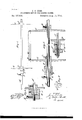
Figure 1 represents a side elevation of the shaft and heads or spiders of the bolting-reel, and Fig. 2 represents the saine in section. Figs. 3 and et represent modifications of the tension-nut. Fig. 5 represents the forked footpiece used to hold the elevator-rib adj ustably to the reel end.
A represents the shaft, mounted and driven in the usual way.
B and C are the heads or spiders to which the bolting-cloth is attached. The head C is held to the shaft A by a set-screw D, or in any other convenient way. In connection with the head B there is a ring or thimble I on the shaft, held to it adj ustably by means of a set-screw K, and there is also an internally-threaded nut F.
In the form shown in Fig. 2 the hub E of the head B is extended and threaded, and the nut F, internally threaded to t the external threads on the hub F., has an internal collar or flange, and the thimble I has an external collar or flange, and the size is so adjusted that the one cannot pass through the other; but the nut F can be passed over thebody of the thimble I until the internal flange on the nut F comes against the external flange on the thimble I, and the threads on the interior of the nut F, meshing with the threads on the hub E, draw the hub E and the thimble I together'. The thimble I is placed on the outside of the reel, and the structure is Serial No. 370,592. (No model.)
so arranged that by fastening the thimble I to the shaft A by means of the set-screw K and loosening the set-screw L the spider B can be drawn forcibly along the shaft and the cloth stretched.
In the form shown in Fig. 3 the parts are reversed. The threaded portion of the hub is inside of the reel and the arrangement of the parts F and I is such that the thimble I forms an abutment, against which the nut F pushes, and thus separates the hub E from the thimble I.
In the form shown in Fig. 4 the sereT is formed on the thimble I and the nut Fabuts against the end of the hub.
In eachcase the arrangement is such that there is a part of variable length between the spider or reel-head and the setting-nut holding the part of variable length to the shaft.
M represents the elevator-bucket attached to the arms of the spider just within the bolting-cloth. This is bolted to the Xed spider C, and is held to the movable spider B by means of a headed screw and forked footpiece N. This holds the bucket securely to the spider and permits the arm of the spider tomove endwise along the bucket M. vThe amount of this motion need not be great, as the amount of end motion of the reel-head is usually through quite a limited space.
Having thus described my invention,WhatI claim as novel, and desire secured to me by Letters Patent, is-
In a bolting-reel, the combination of a fixed head, a movable head arranged to be adjustably held upon the shaft to both heads, an elevator fastened to the xed head, a slotted foot-piece fastened to the movable head, and a sliding joint connection between the said elevator-bucket and the said foot-piece, substantially as and for the purpose described.
' JAMES C. DIBB.
Witnesses:
CHARLES H. FrsK, D. E. WLLBER.
Publications (1)
| Publication Number | Publication Date |
|---|---|
| US457638A true US457638A (en) | 1891-08-11 |
Family
ID=2526513
Family Applications (1)
| Application Number | Title | Priority Date | Filing Date |
|---|---|---|---|
| US457638D Expired - Lifetime US457638A (en) | Stretching device for bolting-cloths |
Country Status (1)
| Country | Link |
|---|---|
| US (1) | US457638A (en) |
-
0
- US US457638D patent/US457638A/en not_active Expired - Lifetime
Similar Documents
| Publication | Publication Date | Title |
|---|---|---|
| US1006950A (en) | Elastic turnbuckle. | |
| US186229A (en) | Improvement in devices for drawing pulleys from shafting | |
| US807299A (en) | Vibrator for medical use. | |
| US206067A (en) | Improvement in feed screws and nuts for rock-drills | |
| US158680A (en) | Improvement in bandage-winders | |
| US1123790A (en) | Grinding mechanism. | |
| US609344A (en) | Bicycle-gearing | |
| US586731A (en) | Churn | |
| US230343A (en) | Thomas eyan | |
| US300647A (en) | Speed-regulator | |
| US347462A (en) | Half to bybon mcneal | |
| US784229A (en) | Machine for dressing or separating flour, &c. | |
| US519984A (en) | Sylvania | |
| US248261A (en) | Take-up and tension for grain-binders | |
| US924341A (en) | Spring-fastening. | |
| US809790A (en) | Feed for coal-cutting machines. | |
| US102066A (en) | Alexander thompson | |
| US573412A (en) | Mounting and driving bolting-reels | |
| US469993A (en) | Bolt and nut fastening device | |
| US143648A (en) | Improvement in pitman-rods | |
| US604836A (en) | Dental engine | |
| US122151A (en) | Improvement in windlasses | |
| USRE5762E (en) | Improvement in toy propellers | |
| US888847A (en) | Rail-bending device. | |
| US255115A (en) | Metal-planer |