US4573244A - Combination condiment grinder and dispenser - Google Patents
Combination condiment grinder and dispenser Download PDFInfo
- Publication number
- US4573244A US4573244A US06/738,827 US73882785A US4573244A US 4573244 A US4573244 A US 4573244A US 73882785 A US73882785 A US 73882785A US 4573244 A US4573244 A US 4573244A
- Authority
- US
- United States
- Prior art keywords
- condiment
- slide member
- grinding
- housing
- lever
- Prior art date
- Legal status (The legal status is an assumption and is not a legal conclusion. Google has not performed a legal analysis and makes no representation as to the accuracy of the status listed.)
- Expired - Lifetime
Links
- 235000013409 condiments Nutrition 0.000 title claims abstract description 61
- 238000000227 grinding Methods 0.000 claims abstract description 45
- 238000010008 shearing Methods 0.000 claims description 9
- 230000006835 compression Effects 0.000 claims description 5
- 238000007906 compression Methods 0.000 claims description 5
- 150000003839 salts Chemical class 0.000 abstract description 6
- 235000002566 Capsicum Nutrition 0.000 abstract description 2
- 239000006002 Pepper Substances 0.000 abstract description 2
- 235000016761 Piper aduncum Nutrition 0.000 abstract description 2
- 235000017804 Piper guineense Nutrition 0.000 abstract description 2
- 244000203593 Piper nigrum Species 0.000 abstract description 2
- 235000008184 Piper nigrum Nutrition 0.000 abstract description 2
- 235000013599 spices Nutrition 0.000 description 7
- 235000013305 food Nutrition 0.000 description 4
- 230000000994 depressogenic effect Effects 0.000 description 3
- 239000000463 material Substances 0.000 description 3
- 210000003813 thumb Anatomy 0.000 description 3
- 210000003811 finger Anatomy 0.000 description 2
- 235000011194 food seasoning agent Nutrition 0.000 description 2
- 230000003213 activating effect Effects 0.000 description 1
- 206010006514 bruxism Diseases 0.000 description 1
- 238000010276 construction Methods 0.000 description 1
- 230000000881 depressing effect Effects 0.000 description 1
- 230000000694 effects Effects 0.000 description 1
- 210000004247 hand Anatomy 0.000 description 1
- 239000002184 metal Substances 0.000 description 1
- 238000002156 mixing Methods 0.000 description 1
- 239000000203 mixture Substances 0.000 description 1
- 239000002245 particle Substances 0.000 description 1
- 238000002360 preparation method Methods 0.000 description 1
- 238000010298 pulverizing process Methods 0.000 description 1
- 230000001105 regulatory effect Effects 0.000 description 1
- 239000007787 solid Substances 0.000 description 1
- 238000003756 stirring Methods 0.000 description 1
- 239000002023 wood Substances 0.000 description 1
Images


Classifications
-
- A—HUMAN NECESSITIES
- A47—FURNITURE; DOMESTIC ARTICLES OR APPLIANCES; COFFEE MILLS; SPICE MILLS; SUCTION CLEANERS IN GENERAL
- A47J—KITCHEN EQUIPMENT; COFFEE MILLS; SPICE MILLS; APPARATUS FOR MAKING BEVERAGES
- A47J42/00—Coffee mills; Spice mills
- A47J42/32—Coffee mills; Spice mills with other grinding or pulverising members
- A47J42/34—Coffee mills; Spice mills with other grinding or pulverising members hand driven
Definitions
- the invention relates to a combination condiment grinder and dispenser apparatus and is more particularly concerned with a hand-held and hand operated grinder mechanism for peppercorns or the like and for holding another seasoning such as salt.
- table grinders or so called peppermills intended for different types of condiments when preparing food has become increasingly popular owing to an increased interest in seasoned dishes and in spices.
- a common feature of most known types of table grinders is that they are intended for grinding one single variety of spice or a single mixture of spices.
- Hand-held and hand-operated spice or condiment grinders or peppermills generally have an elongated cylindrical housing which is asthetically configured as an attractive item of tableware.
- the so called spice grinders or peppermills enclose a condiment storage chamber and the grinding mechanism dispenses the ground condiments through an opening provided in the bottom.
- the most widely used type of spice or pepper grinders have a crank arm directly connected to the shaft of the grinding mechanism which is turned continuously and unidirectionally with one hand of the user while the other hand holds the peppermill over the food generally vertically with the ground condiment or spice dropping, out of the bottom.
- crank-type grinders which are structured as indicated above that both hands are needed for operating the same. This can be inconvenient if the user wants to stir food while mixing condiment, otherwise has one hand occupied or if the user is handicapped.
- U.S. Pat. Nos. 3,055,599 and 3,096,036 are both examples of the spring loaded and thumb depressed central spindle mechanism with a serrated surface for grinding peppercorns together with the cooperating tapered surface. As a result, the pulverized or ground pieces of peppercorn are dropped on through the exit aperture at the lower end of the peppermill housing.
- U.S. Pat. No. 2,698,719 is a depression-type mechanism also using a cutter-type central spindle device in cooperation with cooperating tapered or conical surfaces to shape or pulverize the condiment.
- U.S. Pat. No. 2,683,566 again is a variation of the thumb depressed device for grinding condiment.
- U.S. Pat. No. 2,876,956 shows a structural variation but which is somewhat similar in principle also to U.S. Pat. No. 2,679,360 for activating the cooperating cutting surfaces by a centrally located spring loaded depression member.
- U.S. Pat. No. 4,374,574 shows a single hand-operated mechanism which involves a clutching mechanism for rotating one cutting or grinder surface relative to a stationary surface.
- the invention comprises a generally upstanding, asthetically configured body or housing which includes a hand and lever recess portion.
- the L-shaped lever has an upstanding or generally vertical portion in the recess and an inwardly extending actuator arm.
- the grinding surface which functions linearly, cooperates with an angled surface to trap the peppercorns or condiment material to crack it and then force it down for final pulverization so that the ground materials can fall out through a gap at the lower end of the housing.
- An anti-dribble feature is included so that upon cessation of grinding no ground particles will continue to fall from the device.
- An upper chamber in the device is also provided with another condiment such as salt.
- An adjustment mechanism is provided to the lower end of the housing for adjusting the coarseness of the grind for the peppercorns or other condiment as desired.
- the device has an adjustability feature to regulate the coarseness of the grind according to the preferences or needs of users.
- the device also contains a chamber for salt or other desired condiment so that two condiments used in food preparation are in the device and can be dispensed by only one hand.
- the device is easily and conveniently loaded both with peppercorns and with a supply of condiment for the upper surface.
- the mechanism for grinding is essentially quite simple and designed for long life and reliability as a commercial and home kitchen and tableware item.
- FIG. 1 is a perspective view of the condiment dispenser grinder housing showing generally its asthetic appearance from the outside;
- FIG. 2 is a cutaway view in perspective showing details of the internal mechanism and the condiment compartments and the general manner of function of the device;
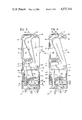
- FIG. 3 is a side elevational view of one-half of the body showing additional details of construction
- FIG. 4 is the same view as side elevational view of FIG. 3 but with the operating lever pivoted so as to further illustrate the grinding action;
- FIG. 5 is a top plan view of the housing or body showing the perforated opening for the condiment in the top compartment;
- FIG. 6 is a bottom plan view of the housing showing the adjustment mechanism for regulating the coarseness of the condiment grinder
- FIG. 7 shows an enlarged cross-sectional view along the line 7--7 of FIG. 3 showing details of a large adjustment or for coarse grind
- FIG. 8 is a similar view as FIG. 7 showing the adjustment feature to a finer grind than in FIG. 7.
- FIGS. 9 and 11 show that the grind adjustment feature may be located in the side wall rather than on the bottom;
- FIGS. 10 and 12 show that the nose of the grinding block is spaced with respect to grinding surface according to type of grind desired
- FIG. 13 shows one form of anti-dribble feature in the form of a rigid lip
- FIGS. 14A and 14B show a flexible anti-dribble device
- FIGS. 14C and 14D show a rotatable anti-dribble device.
- the invention generally designated by the number 10, has an upper end 12, a lower end 14, side surfaces 16, back surface 18 and a front surface 20.
- the front surface of the housing can be seen to include a lever recess area which begins approximately half-way up the front edge surface 20 and which extends inwardly generally horizontally a short distance and then angles upwardly and rearwardly.
- the recess is in close proximity to the top surface 12 and is roughly one-half the front to back dimension at its deepest.
- Recess surface 22 extends inwardly and merges with surface 24 which angles upwardly and rearwardly. The recess then extends outwardly again as surface 26 near the top surface 12 of the housing or body.
- the surfaces as generally described are not precisely defined by sharp corners or edges.
- the device is rounded at corners and along edges so that it presents an asthetically pleasing shape and configuration.
- the description of the recess-defining surfaces are included generally for convenience sake and to aid in description of the device.
- the invention will be made from two matching halves which will join along a centerline 28 as can be seen in most of the views in the drawings.
- each half of the plastic body includes internal wall structure of a predetermined thickness and predetermined location. While plastic has been specified, wood or light metal may also be used as the body material.
- the top surface 12 has its wall up to centerline 28 as described above.
- the two halves of the body include horizontal wall 30 which is located approximately midway down from the top of the body and which horizontal wall 30 also joins with upwardly and rearwardly extending compartment wall 32 which near the top reverse curves forwardly as wall 34 and which finally joins top surface 12 with upwardly extending wall 36.
- walls 30, 32, 34 and 36 as well as the outside walls of course are joined together to define condiment chamber 38.
- Chamber 38 at the top is seen to have rectangular or other shaped opening 40 with perforated slide plate 42 reciprocally movable therein so that compartment 38 can be replenished with condiment or seasoning such as salt when desired.
- the lower portion of the housing shows a stop wall 50 extending horizontally in from the front edge 20 of the device to approximately two-thirds the way to the rear edge surface 18 of the housing.
- a bottom wall 52 forming the lower exterior of the device.
- a ramp wall 54 extending from the front edge 20 downwardly and rearwardly toward the back surface of the device terminates at a point 56 at a distance of slightly halfway past the vertical centerline of the dispenser body.
- a horizontal dividing wall 58 extends from point 56 generally horizontally forwardly to the front surface 20 as is seen in the drawings.
- a vertical spacing is defined between walls 52 and wall 58 for purposes which are now to be described.
- adjustable grinding block 60 which has a tapered ramp surface 62 upper, and lower surfaces which are in close proximity to wall 58 and wall 52 respectively, and a rear surface 64 as well as shearing edge 63.
- An eccentric shaft is aligned between two openings in the upper and lower walls 58 and 52 such that in one position as shown in FIG. 8 the grinding block 60 is moved rearwardly for a fine grind and may be moved toward the front edge 20 when a coarser grind is desired.
- a simple manipulation of the finger member 66 to turn shaft 68 which in turn moves cam 70 to move the block. Note that the shaft 68 is aligned in the openings in spaced apart walls 52 and 58. As it is turned, the cam moves the block toward or away from a slide member 88.
- the mechanism includes the L-shaped lever member number 80 having generally vertical and longer arm 82 which pivots around axis 84 and which has an inwardly extending actuating arm 86.
- a nose portion on arm 86 engages a movable or slide member 88 having coacting grinding teeth or serrations 90 which coact with the grinder block 60, the angled surface 62 and shearing edge 63 described above.
- a compression spring 92 is disposed behind the slide member 88 and which slide member has an outwardly or rearwardly extending arm 94 which confines compression spring 92 such that slide bar 88 is always biased upwardly against the pressure exerted by arm 86 of lever 80.
- An opening 96 is defined between the two halves in the front wall 20 so that slide cover 98 can be retracted away from the opening and a fresh supply of peppercorns or condiment inserted therein into compartment 55.
- the inwardly extending lever portion 86 is located between compartment wall 30 of the upper compartment and wall 50 of lower compartment 55.
- condiment grinder 10 has the grind adjustment feature mounted on the side wall rather than on the bottom. It will be noted that a shaft connected to the indicator and finger member 104 is offset with respect to eccentric 102 which moves in opening 100 in block 60. Three setting for fine, coarse and medium grinds are provided.
- FIGS. 13 and 14A through 14D illustrate the several forms which a retainer or anti-dribble feature for fines may take.
- an elongated lip 106 formed along the bottom end of lever member 88 comprises a solid anti-dribble device to close off the ejection slot.
- FIGS. 14A and 14B include flexible member 108 mounted in any desirable fashion on the bottom ends of member 88.
- the ejection slot again is closed off to prevent dribbling of fines when the grinder is not in use.
- FIGS. 14C and 14D illustrate a rotatable member 110, 112 which may have spring 114 to bias part 110 outwardly.
- the spring 114 biases the member 110, 112 open when the slide 88 is moved downwardly.
Landscapes
- Engineering & Computer Science (AREA)
- Mechanical Engineering (AREA)
- Food Science & Technology (AREA)
- Seasonings (AREA)
- Food-Manufacturing Devices (AREA)
- Table Devices Or Equipment (AREA)
- Jellies, Jams, And Syrups (AREA)
Abstract
Description
Claims (20)
Priority Applications (8)
| Application Number | Priority Date | Filing Date | Title |
|---|---|---|---|
| US06/738,827 US4573244A (en) | 1985-05-29 | 1985-05-29 | Combination condiment grinder and dispenser |
| US06/792,455 US4697749A (en) | 1985-05-29 | 1985-10-29 | Combination condiment grinder and dispenser |
| CA000509275A CA1249793A (en) | 1985-05-29 | 1986-05-15 | Combination condiment grinder and dispenser |
| AU57652/86A AU568038B2 (en) | 1985-05-29 | 1986-05-21 | Spice or pepper grinder |
| AT86106967T ATE46074T1 (en) | 1985-05-29 | 1986-05-22 | COMBINED SPICE GRINDER AND SHAKER. |
| DE8686106967T DE3665398D1 (en) | 1985-05-29 | 1986-05-22 | Combination condiment grinder and dispenser |
| EP86106967A EP0205935B1 (en) | 1985-05-29 | 1986-05-22 | Combination condiment grinder and dispenser |
| HK470/93A HK47093A (en) | 1985-05-29 | 1993-05-13 | Combination condiment grinder and dispenser |
Applications Claiming Priority (1)
| Application Number | Priority Date | Filing Date | Title |
|---|---|---|---|
| US06/738,827 US4573244A (en) | 1985-05-29 | 1985-05-29 | Combination condiment grinder and dispenser |
Related Child Applications (1)
| Application Number | Title | Priority Date | Filing Date |
|---|---|---|---|
| US06/792,455 Division US4697749A (en) | 1985-05-29 | 1985-10-29 | Combination condiment grinder and dispenser |
Publications (1)
| Publication Number | Publication Date |
|---|---|
| US4573244A true US4573244A (en) | 1986-03-04 |
Family
ID=24969650
Family Applications (1)
| Application Number | Title | Priority Date | Filing Date |
|---|---|---|---|
| US06/738,827 Expired - Lifetime US4573244A (en) | 1985-05-29 | 1985-05-29 | Combination condiment grinder and dispenser |
Country Status (7)
| Country | Link |
|---|---|
| US (1) | US4573244A (en) |
| EP (1) | EP0205935B1 (en) |
| AT (1) | ATE46074T1 (en) |
| AU (1) | AU568038B2 (en) |
| CA (1) | CA1249793A (en) |
| DE (1) | DE3665398D1 (en) |
| HK (1) | HK47093A (en) |
Cited By (15)
| Publication number | Priority date | Publication date | Assignee | Title |
|---|---|---|---|---|
| US4697749A (en) * | 1985-05-29 | 1987-10-06 | F. Bartow Fite | Combination condiment grinder and dispenser |
| US5199655A (en) * | 1991-12-02 | 1993-04-06 | Yang Hang Te | Pistol-shaped pepper grinder |
| US6277424B1 (en) | 1999-07-22 | 2001-08-21 | Mongkol Kwangwaropas | Pepper seed polishing machine |
| WO2002019880A2 (en) | 2000-09-07 | 2002-03-14 | Chef'n Corporation | Multiple chamber condiment grinder |
| US6511006B1 (en) | 2001-07-16 | 2003-01-28 | Chef'n Corporation | Condiment grinder residue catch |
| US6568616B1 (en) * | 2002-10-11 | 2003-05-27 | Samson Bright Industrial Co. Ltd. | Hand-held condiment grinder |
| US20030192971A1 (en) * | 2002-04-16 | 2003-10-16 | Chef'n Corporation | Apparatus for grinding material, such as spice or grain |
| US20080229585A1 (en) * | 2007-03-22 | 2008-09-25 | Robert Kelly | Seasoning spoon |
| US20090039188A1 (en) * | 2007-08-09 | 2009-02-12 | Robbins Industries, Inc. | Condiment grinder and dispenser |
| US20090078807A1 (en) * | 2007-09-21 | 2009-03-26 | Yu Wing Tang | Adjustable grinder |
| US20090200410A1 (en) * | 2007-11-09 | 2009-08-13 | Chef'n Corporation | Modular grinding core and grinding devices incorporating the same |
| US20100200685A1 (en) * | 2009-02-09 | 2010-08-12 | Yienn Lih Enterprise Co., Ltd. | Pepper mill |
| USD777523S1 (en) | 2013-06-12 | 2017-01-31 | Catherine Beers | Seasoning dispenser |
| US20170181580A1 (en) * | 2015-12-24 | 2017-06-29 | King's Flair Marketing Limited | Food processing device |
| US11737607B2 (en) | 2021-02-16 | 2023-08-29 | Edward Scott Rubin | Cooking utensil with seasoning grinder integrated into the handle |
Families Citing this family (3)
| Publication number | Priority date | Publication date | Assignee | Title |
|---|---|---|---|---|
| US6676052B2 (en) * | 2001-09-10 | 2004-01-13 | Yienn Lih Enterprise Co., Ltd. | Pepper grinding tool with a sideways lever operated with one hand |
| US7784721B2 (en) * | 2007-03-06 | 2010-08-31 | Lifetime Brands, Inc. | Spice grinding and dispensing device |
| PL3357382T3 (en) | 2017-02-02 | 2019-09-30 | Keeeper Gmbh | Distribution device with an outer container and a movable inner container therein |
Citations (11)
| Publication number | Priority date | Publication date | Assignee | Title |
|---|---|---|---|---|
| US1930056A (en) * | 1930-12-12 | 1933-10-10 | Paul C Klingler | Ice crusher |
| US2045058A (en) * | 1933-11-10 | 1936-06-23 | Teves Kg Alfred | Grinding mill |
| US2047566A (en) * | 1934-06-20 | 1936-07-14 | Paul C Klingler | Ice crusher |
| US2679360A (en) * | 1950-11-08 | 1954-05-25 | Arni Arnold | Hand supported comminutor with reciprocable grinding member |
| US2683566A (en) * | 1951-06-16 | 1954-07-13 | John W Bentley | Pepper mill |
| US2698719A (en) * | 1950-11-27 | 1955-01-04 | Edward C Heard | Pepper mill |
| US2876956A (en) * | 1956-02-13 | 1959-03-10 | John W Bentley | Pepper mill for table use and the like |
| US3055599A (en) * | 1959-11-09 | 1962-09-25 | Cowles Edwin | Pepper mills |
| US3096036A (en) * | 1961-02-23 | 1963-07-02 | Bo Mer Mfg Corp | Pepper mills |
| US3827641A (en) * | 1972-09-29 | 1974-08-06 | Gullaskrufs Glasbruks Ab | Multi-purpose grinding mill |
| US4374574A (en) * | 1980-11-03 | 1983-02-22 | Tom David | Condiment grinder-dispenser |
Family Cites Families (5)
| Publication number | Priority date | Publication date | Assignee | Title |
|---|---|---|---|---|
| AT23322B (en) * | 1904-12-21 | 1906-03-10 | Ernst Charles Fischer | Spice container. |
| FR911245A (en) * | 1945-06-05 | 1946-07-02 | Table salt mill | |
| AU496605B2 (en) * | 1976-03-01 | 1977-09-08 | Figge Johansson Karl | Spice mill |
| WO1984000484A1 (en) * | 1982-07-29 | 1984-02-16 | John Cas Czelen | Condiment grinder |
| AU2773684A (en) * | 1984-05-07 | 1985-11-14 | Hofmann G.m.b.H. | Shaker |
-
1985
- 1985-05-29 US US06/738,827 patent/US4573244A/en not_active Expired - Lifetime
-
1986
- 1986-05-15 CA CA000509275A patent/CA1249793A/en not_active Expired
- 1986-05-21 AU AU57652/86A patent/AU568038B2/en not_active Expired
- 1986-05-22 DE DE8686106967T patent/DE3665398D1/en not_active Expired
- 1986-05-22 EP EP86106967A patent/EP0205935B1/en not_active Expired
- 1986-05-22 AT AT86106967T patent/ATE46074T1/en not_active IP Right Cessation
-
1993
- 1993-05-13 HK HK470/93A patent/HK47093A/en not_active IP Right Cessation
Patent Citations (11)
| Publication number | Priority date | Publication date | Assignee | Title |
|---|---|---|---|---|
| US1930056A (en) * | 1930-12-12 | 1933-10-10 | Paul C Klingler | Ice crusher |
| US2045058A (en) * | 1933-11-10 | 1936-06-23 | Teves Kg Alfred | Grinding mill |
| US2047566A (en) * | 1934-06-20 | 1936-07-14 | Paul C Klingler | Ice crusher |
| US2679360A (en) * | 1950-11-08 | 1954-05-25 | Arni Arnold | Hand supported comminutor with reciprocable grinding member |
| US2698719A (en) * | 1950-11-27 | 1955-01-04 | Edward C Heard | Pepper mill |
| US2683566A (en) * | 1951-06-16 | 1954-07-13 | John W Bentley | Pepper mill |
| US2876956A (en) * | 1956-02-13 | 1959-03-10 | John W Bentley | Pepper mill for table use and the like |
| US3055599A (en) * | 1959-11-09 | 1962-09-25 | Cowles Edwin | Pepper mills |
| US3096036A (en) * | 1961-02-23 | 1963-07-02 | Bo Mer Mfg Corp | Pepper mills |
| US3827641A (en) * | 1972-09-29 | 1974-08-06 | Gullaskrufs Glasbruks Ab | Multi-purpose grinding mill |
| US4374574A (en) * | 1980-11-03 | 1983-02-22 | Tom David | Condiment grinder-dispenser |
Cited By (27)
| Publication number | Priority date | Publication date | Assignee | Title |
|---|---|---|---|---|
| US4697749A (en) * | 1985-05-29 | 1987-10-06 | F. Bartow Fite | Combination condiment grinder and dispenser |
| US5199655A (en) * | 1991-12-02 | 1993-04-06 | Yang Hang Te | Pistol-shaped pepper grinder |
| US6277424B1 (en) | 1999-07-22 | 2001-08-21 | Mongkol Kwangwaropas | Pepper seed polishing machine |
| US6926214B2 (en) | 2000-09-07 | 2005-08-09 | Chef'n Corporation | Multiple chamber condiment grinder |
| WO2002019880A2 (en) | 2000-09-07 | 2002-03-14 | Chef'n Corporation | Multiple chamber condiment grinder |
| US7210643B2 (en) | 2000-09-07 | 2007-05-01 | Chef'n Corporation | Multiple chamber condiment grinder |
| US6672524B1 (en) | 2000-09-07 | 2004-01-06 | Chef'n Corporation | Multiple chamber condiment grinder |
| US20040159726A1 (en) * | 2000-09-07 | 2004-08-19 | Holcomb David A. | Multiple chamber condiment grinder |
| EP1683453A2 (en) | 2000-09-07 | 2006-07-26 | Chef'n Corporation | Multiple chamber condiment grinder |
| US20060049292A1 (en) * | 2000-09-07 | 2006-03-09 | Chef'n Corporation | Multiple chamber condiment grinder |
| US6511006B1 (en) | 2001-07-16 | 2003-01-28 | Chef'n Corporation | Condiment grinder residue catch |
| US20030192971A1 (en) * | 2002-04-16 | 2003-10-16 | Chef'n Corporation | Apparatus for grinding material, such as spice or grain |
| US6871808B2 (en) | 2002-04-16 | 2005-03-29 | Chef'n Corporation | Apparatus for grinding material, such as spice or grain |
| US20050133646A1 (en) * | 2002-04-16 | 2005-06-23 | Chef'n Corporation | Apparatus for grinding material, such as spice or grain |
| US6568616B1 (en) * | 2002-10-11 | 2003-05-27 | Samson Bright Industrial Co. Ltd. | Hand-held condiment grinder |
| US20080229585A1 (en) * | 2007-03-22 | 2008-09-25 | Robert Kelly | Seasoning spoon |
| US7648094B2 (en) | 2007-08-09 | 2010-01-19 | Fox Run Usa, Llc | Condiment grinder and dispenser |
| US20090039188A1 (en) * | 2007-08-09 | 2009-02-12 | Robbins Industries, Inc. | Condiment grinder and dispenser |
| US20090078807A1 (en) * | 2007-09-21 | 2009-03-26 | Yu Wing Tang | Adjustable grinder |
| US20090200410A1 (en) * | 2007-11-09 | 2009-08-13 | Chef'n Corporation | Modular grinding core and grinding devices incorporating the same |
| US7828237B2 (en) | 2007-11-09 | 2010-11-09 | Chef'n Corporation | Modular grinding core and grinding devices incorporating the same |
| US20100200685A1 (en) * | 2009-02-09 | 2010-08-12 | Yienn Lih Enterprise Co., Ltd. | Pepper mill |
| US8011609B2 (en) * | 2009-02-09 | 2011-09-06 | Yienn Lih Enterprise Co., Ltd. | Pepper mill |
| USD777523S1 (en) | 2013-06-12 | 2017-01-31 | Catherine Beers | Seasoning dispenser |
| US20170181580A1 (en) * | 2015-12-24 | 2017-06-29 | King's Flair Marketing Limited | Food processing device |
| US10674871B2 (en) * | 2015-12-24 | 2020-06-09 | King's Flair Marketing Limited | Food processing device |
| US11737607B2 (en) | 2021-02-16 | 2023-08-29 | Edward Scott Rubin | Cooking utensil with seasoning grinder integrated into the handle |
Also Published As
| Publication number | Publication date |
|---|---|
| CA1249793A (en) | 1989-02-07 |
| EP0205935A1 (en) | 1986-12-30 |
| HK47093A (en) | 1993-05-21 |
| ATE46074T1 (en) | 1989-09-15 |
| EP0205935B1 (en) | 1989-09-06 |
| AU5765286A (en) | 1986-12-04 |
| DE3665398D1 (en) | 1989-10-12 |
| AU568038B2 (en) | 1987-12-10 |
Similar Documents
| Publication | Publication Date | Title |
|---|---|---|
| US4697749A (en) | Combination condiment grinder and dispenser | |
| US4573244A (en) | Combination condiment grinder and dispenser | |
| US11642805B2 (en) | Dual sided razor | |
| US7644883B2 (en) | Food processor lid | |
| US20080093489A1 (en) | Spice Grinder Assembly with Grind Adjusting Wheel | |
| US7210643B2 (en) | Multiple chamber condiment grinder | |
| US5651506A (en) | Multi-compartment condiment grinder | |
| RU2473296C2 (en) | System of metering coffee and tea | |
| US20040200075A1 (en) | Dispensing utensil | |
| US6793168B1 (en) | Condiment grinder | |
| US7648094B2 (en) | Condiment grinder and dispenser | |
| AU2001289195A1 (en) | Multiple chamber condiment grinder | |
| US6568616B1 (en) | Hand-held condiment grinder | |
| JP2000005024A (en) | Daily necessities with packing container | |
| US10219635B2 (en) | Nut dispenser device | |
| US5343800A (en) | Seasoning can structure | |
| CN218219990U (en) | Grinding mechanism and bean grinder | |
| US20220095670A1 (en) | Finger-operated herb grinder | |
| US20240008685A1 (en) | Compact manual coffee grinder machine, for domestic use | |
| US20240237858A1 (en) | Rotary Grater And/Or Slicer | |
| KR20180001820U (en) | Coffee grinder jig and coffee grinder with jig | |
| JP2022186553A (en) | Seasoning mill | |
| US594205A (en) | Pancake-turner | |
| JP2519462Y2 (en) | mill | |
| EP0329759A1 (en) | Peppermill having disposable cartridge |
Legal Events
| Date | Code | Title | Description |
|---|---|---|---|
| AS | Assignment |
Owner name: F. BARTOW FITE, 1706 HOWELL PLACE, SEATTLE, WASHIN Free format text: ASSIGNMENT OF ASSIGNORS INTEREST.;ASSIGNORS:HOLCOMB, DAVID A.;TRYON, JAMES A.;REEL/FRAME:004428/0448 Effective date: 19850711 |
|
| STCF | Information on status: patent grant |
Free format text: PATENTED CASE |
|
| FEPP | Fee payment procedure |
Free format text: PAYOR NUMBER ASSIGNED (ORIGINAL EVENT CODE: ASPN); ENTITY STATUS OF PATENT OWNER: SMALL ENTITY |
|
| FPAY | Fee payment |
Year of fee payment: 4 |
|
| FPAY | Fee payment |
Year of fee payment: 8 |
|
| AS | Assignment |
Owner name: CHEF'N CORPORATION, WASHINGTON Free format text: ASSIGNMENT OF ASSIGNORS INTEREST;ASSIGNOR:FITE, F. BARTOW;REEL/FRAME:007986/0248 Effective date: 19960521 |
|
| FEPP | Fee payment procedure |
Free format text: PAYOR NUMBER ASSIGNED (ORIGINAL EVENT CODE: ASPN); ENTITY STATUS OF PATENT OWNER: SMALL ENTITY Free format text: PAYER NUMBER DE-ASSIGNED (ORIGINAL EVENT CODE: RMPN); ENTITY STATUS OF PATENT OWNER: SMALL ENTITY |
|
| FPAY | Fee payment |
Year of fee payment: 12 |
|
| AS | Assignment |
Owner name: JPMORGAN CHASE BANK, N.A., WASHINGTON Free format text: SECURITY AGREEMENT;ASSIGNOR:THE CHEF'N CORPORATION;REEL/FRAME:027240/0270 Effective date: 20111116 |
|
| AS | Assignment |
Owner name: CAPITALSOUTH PARTNERS FUND II LIMITED PARTNERSHIP, Free format text: SECURITY AGREEMENT;ASSIGNORS:THE CHEF'N CORPORATION;CHEF'N ACQUISITION, INC.;REEL/FRAME:027255/0258 Effective date: 20111116 Owner name: CAPITALSOUTH PARTNERS SBIC FUND III, L.P., NORTH C Free format text: SECURITY AGREEMENT;ASSIGNORS:THE CHEF'N CORPORATION;CHEF'N ACQUISITION, INC.;REEL/FRAME:027255/0258 Effective date: 20111116 |
|
| AS | Assignment |
Owner name: THE CHEF'N CORPORATION, WASHINGTON Free format text: RELEASE BY SECURED PARTY;ASSIGNORS:CAPITALSOUTH PARTNERS FUND II LIMITED PARTNERSHIP;CAPITALSOUTH PARTNERS SBIC FUND III, L.P.;REEL/FRAME:034760/0293 Effective date: 20141223 |