US4568826A - Ambient lighting detection mechanism - Google Patents
Ambient lighting detection mechanism Download PDFInfo
- Publication number
- US4568826A US4568826A US06/494,406 US49440683A US4568826A US 4568826 A US4568826 A US 4568826A US 49440683 A US49440683 A US 49440683A US 4568826 A US4568826 A US 4568826A
- Authority
- US
- United States
- Prior art keywords
- collar
- photocell
- body member
- aperture
- light
- Prior art date
- Legal status (The legal status is an assumption and is not a legal conclusion. Google has not performed a legal analysis and makes no representation as to the accuracy of the status listed.)
- Expired - Fee Related
Links
- 238000001514 detection method Methods 0.000 title claims abstract description 13
- 238000000034 method Methods 0.000 claims description 4
- 230000001105 regulatory effect Effects 0.000 claims 2
- 230000002093 peripheral effect Effects 0.000 claims 1
- 239000000463 material Substances 0.000 description 5
- 238000009434 installation Methods 0.000 description 2
- 230000035945 sensitivity Effects 0.000 description 2
- 239000004593 Epoxy Substances 0.000 description 1
- 238000010276 construction Methods 0.000 description 1
- 230000003247 decreasing effect Effects 0.000 description 1
- 230000009977 dual effect Effects 0.000 description 1
- 238000010292 electrical insulation Methods 0.000 description 1
- 239000011521 glass Substances 0.000 description 1
- 230000000284 resting effect Effects 0.000 description 1
Images

Classifications
-
- G—PHYSICS
- G01—MEASURING; TESTING
- G01J—MEASUREMENT OF INTENSITY, VELOCITY, SPECTRAL CONTENT, POLARISATION, PHASE OR PULSE CHARACTERISTICS OF INFRARED, VISIBLE OR ULTRAVIOLET LIGHT; COLORIMETRY; RADIATION PYROMETRY
- G01J1/00—Photometry, e.g. photographic exposure meter
- G01J1/02—Details
-
- F—MECHANICAL ENGINEERING; LIGHTING; HEATING; WEAPONS; BLASTING
- F21—LIGHTING
- F21V—FUNCTIONAL FEATURES OR DETAILS OF LIGHTING DEVICES OR SYSTEMS THEREOF; STRUCTURAL COMBINATIONS OF LIGHTING DEVICES WITH OTHER ARTICLES, NOT OTHERWISE PROVIDED FOR
- F21V23/00—Arrangement of electric circuit elements in or on lighting devices
-
- H—ELECTRICITY
- H05—ELECTRIC TECHNIQUES NOT OTHERWISE PROVIDED FOR
- H05B—ELECTRIC HEATING; ELECTRIC LIGHT SOURCES NOT OTHERWISE PROVIDED FOR; CIRCUIT ARRANGEMENTS FOR ELECTRIC LIGHT SOURCES, IN GENERAL
- H05B41/00—Circuit arrangements or apparatus for igniting or operating discharge lamps
- H05B41/02—Details
-
- H—ELECTRICITY
- H05—ELECTRIC TECHNIQUES NOT OTHERWISE PROVIDED FOR
- H05B—ELECTRIC HEATING; ELECTRIC LIGHT SOURCES NOT OTHERWISE PROVIDED FOR; CIRCUIT ARRANGEMENTS FOR ELECTRIC LIGHT SOURCES, IN GENERAL
- H05B41/00—Circuit arrangements or apparatus for igniting or operating discharge lamps
- H05B41/14—Circuit arrangements
- H05B41/36—Controlling
- H05B41/38—Controlling the intensity of light
- H05B41/39—Controlling the intensity of light continuously
- H05B41/392—Controlling the intensity of light continuously using semiconductor devices, e.g. thyristor
- H05B41/3921—Controlling the intensity of light continuously using semiconductor devices, e.g. thyristor with possibility of light intensity variations
- H05B41/3922—Controlling the intensity of light continuously using semiconductor devices, e.g. thyristor with possibility of light intensity variations and measurement of the incident light
-
- G—PHYSICS
- G01—MEASURING; TESTING
- G01J—MEASUREMENT OF INTENSITY, VELOCITY, SPECTRAL CONTENT, POLARISATION, PHASE OR PULSE CHARACTERISTICS OF INFRARED, VISIBLE OR ULTRAVIOLET LIGHT; COLORIMETRY; RADIATION PYROMETRY
- G01J1/00—Photometry, e.g. photographic exposure meter
- G01J1/02—Details
- G01J1/0266—Field-of-view determination; Aiming or pointing of a photometer; Adjusting alignment; Encoding angular position; Size of the measurement area; Position tracking; Photodetection involving different fields of view for a single detector
Definitions
- the present invention is related generally to an apparatus for detecting ambient lighting levels within a given area and, more particularly, to a system and method for controlling the lighting level of gas discharge lamps through the use of the detected ambient level of the light in the immediate vicinity of the lamps.
- photocell arrangement to detect the presence and/or intensity of light within a given area to control the energization of the light is well known in the art.
- the photocell is connected in a feedback loop of the circuitry, to cause increased or decreased energization of the lamp, and provide a stable or predetermined level of lighting output from the system. Examples of lighting systems incorporating such a photocell are shown by U.S. patent application Ser. No. 286,770 filed July 27, 1981, now U.S. Pat. No. 4,464,610, entitled Modular Lighting Control with Circulating Inductor; Ser. No. 309,260 filed Oct. 7, 1981, now U.S. Pat. No. 4,463,287, entitled Four Lamp Modular Lighting Control; Ser. No.
- This invention is concerned with the mounting of a photocell arrangement for ready access to light in the immediate vicinity of the lighting system, and a particular construction of the photocell arrangement providing for ease of adjustment of the amount of light impinging upon the pohotocell.
- the present invention provides a mounting arrangement for a photocell in the immediate vicinity of the lighting system to enable detection of ambient lighting by the photocell within the area. Mounting of the photocell arrangement is arranged to minimize time, additional hardware, and installation equipment. This improvement and others is the result of an adjustable lighting level detection mechanism designed for ease of installation, adjustment and operation.
- Efficient operation of the photocell is directly related to the ability of the device to pick up ambient lighting within the room for use in controlling the lighting provided by the fixture.
- the ability to change the sensitivity of the photocell detection means involves altering the field of view of the photocell by opening or closing the lens passage to the photocell.
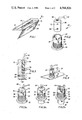
- FIG. 1 is a perspective view of a fluorescent lighting fixture including a light detector constructed in accordance with the present invention
- FIG. 2 is an exploded view of the light detector of the present invention
- FIG. 3 is a cross-sectional view of a body member of the light detector
- FIG. 4 is a perspective view of a portion of the light in FIG. 1 illustrating the mounting of the light detector
- FIG. 5a, 5b and 5c are perspective views of the light detector of the present invention illustrating three operating positions for the body of the detector;
- FIG. 6 is a partial cross-sectional view of an alternate embodiment for mounting the light detector of the present invention.
- FIG. 7 is an exploded perspective view of the mounting hardware used in the embodiment shown in FIG. 6;
- FIG. 8 is a plan view of the embodiment and detector shown in FIG. 6.
- FIG. 1 A four lamp fluorescent fixture 10 is shown in FIG. 1 including a modular lighting control system such as shown in U.S. patent application Ser. No. 309,260 filed Oct. 7, 1981. This application is assigned to the same assignee as the present application. While the fluorescent bulbs are not shown in the fixture of FIG. 1, the base structure 12 includes dual ballasts 14 mounted therein and a control circuit 16 such as that shown in the above-identified U.S. application. Base 12 is provided with a diffuser 18 mounted on a hinge at one edge (not shown) and having a latch at the other edge (now shown). A lighting level detector 20 is shown mounted within diffuser 18 of the lamp and is electrically connected to control circuit 16, as further explained in the above-identified U.S. patent application.
- detector 20 includes a collar 26 and a body 28. Collar 26 has a cylindrical opening 30 therethrough into which body 28 fits in a sliding relationship. An external flange 32 is provided as an integral portion of collar 26 near one edge thereof and external threads 34 are provided on the surface of the collar at the end near flange 32. As can be seen in FIG. 4, detector 20 is mounted within a surface such as diffuser 18 by providing an opening through the surface large enough for collar 26 but not flange 32.
- Collar 26 further includes first and second slots 38 and 40 within the surface of the collar extending axially from the edge opposite flange 32. The purpose of these slots will be more readily understood with the aid of material and figures to be explained hereinafter.
- Body 28 slidingly engages the inner surface of collar 26, and may be constructed of any one of a number of materials. Plastic is the preferred material for the body due to the relative ease in working with the material as well as the electrical insulation abilities.
- the body has a generally cylindrical shape with concentric apertures 46 and 48 extending axially therethrough. While the apertures are in an axial direction, they need not be concentric with the center of body 28, but only concentric with one another.
- a photocell 50 is positioned near the juncture of the two concentric apertures. Electrical connections 52 are made between photocell 50 and a pair of electrical leads 54 near the lower end of aperture 46. A plug 56 is inserted into aperture 46 near electrical connections 52 and the balance of aperture 46 is filled with an epoxy material 58 to seal the photocell and its connections within the body.
- a diffuser 60 constructed of glass or plastic, closes the end of aperture 48. Diffuser 60 operates to focus light into aperture 48 and thus onto photocell 50.
- An aperture 64 extends radially into body 28 and intersects aperture 48.
- the surface of aperture 64 is threaded to matingly engage a set screw 66.
- set screw 66 By turning set screw 66 either further into aperture 64 or out of the aperture, the amount of light directed into aperture 48 and at the photocell may be adjusted. In this way, the sensitivity of the photocell and thus the detector may be adjusted by appropriate movement of set screw 66.
- FIG. 5a illustrates a first operational position for detector 20 wherein body 28 does not extend below collar 26. This position is maintained as a result of lug 70 resting on the top edge of collar 26. In this position, diffuser 60 is essentially flush with the outer surface of collar 26 and directs light into aperture 48 and the photocell.
- body 28 and thus diffuser 60 are at a position below the lower edge of the collar.
- This alternate position is the preferred operational position for the detector and allows preset light entry through diffuser 60 and onto photocell 50.
- FIG. 5c illustrates detection device 20 in a photocell setting position wherein lug 70 has been positioned into slot 40 to allow body 28 to extend sufficiently to expose set screw 66. In this position, the amount of light impinging upon photocell 50 is adjusted as noted above by turning the set screw until the appropriate position has been reached. Once the adjustment is complete, body 28 should be returned to either the first or second operating positions shown in FIGS. 5a and 5b, respectively.
- FIG. 6 An alternate method of securing detection device 20 for operation is shown in FIG. 6.
- Fluorescent lighting fixtures with which the detection device is used are generally mounted within a suspended ceiling. These suspended ceilings are supported by T-bars 74, one of which is shown in FIG. 6.
- the design of the T-bars is relatively conventional and is manufactured by a number of concerns such as Donn Corporation. Rather than mount detection device 20 within the diffuser of lighting fixture 10, the device may be attached to one of the T-bars supporting the ceiling.
- a first mounting plate 76 has an overturned edge designed to engage the horizontal flange of T-bar 74.
- the surface of plate 76 has an aperture 78 therethrough of sufficient diameter to allow passage of collar 26 of the detector.
- a second plate 80 likewise has an aperture 82 of sufficient size to allow passage of collar 26 therethrough.
- First and second plates 76 and 80 are arranged with T-bar 74 and detection device 20 as shown in FIGS. 6 and 8. Collar 26 is passed through aperture 78 of plate 76 such that flange 32 engages the face of the first plate. Second plate 80 is positioned over the collar and nut 36 is threaded onto threads 34 to bind plates 76 and 80 to the T-bar.
Abstract
Description
Claims (4)
Priority Applications (1)
| Application Number | Priority Date | Filing Date | Title |
|---|---|---|---|
| US06/494,406 US4568826A (en) | 1983-05-13 | 1983-05-13 | Ambient lighting detection mechanism |
Applications Claiming Priority (1)
| Application Number | Priority Date | Filing Date | Title |
|---|---|---|---|
| US06/494,406 US4568826A (en) | 1983-05-13 | 1983-05-13 | Ambient lighting detection mechanism |
Publications (1)
| Publication Number | Publication Date |
|---|---|
| US4568826A true US4568826A (en) | 1986-02-04 |
Family
ID=23964344
Family Applications (1)
| Application Number | Title | Priority Date | Filing Date |
|---|---|---|---|
| US06/494,406 Expired - Fee Related US4568826A (en) | 1983-05-13 | 1983-05-13 | Ambient lighting detection mechanism |
Country Status (1)
| Country | Link |
|---|---|
| US (1) | US4568826A (en) |
Cited By (12)
| Publication number | Priority date | Publication date | Assignee | Title |
|---|---|---|---|---|
| US5039853A (en) * | 1989-06-29 | 1991-08-13 | Multipoint Control Systems, Inc. | Constant-current light-sensing system and improved sensor housing |
| US5245183A (en) * | 1992-09-10 | 1993-09-14 | The United States Of America As Represented By The Secretary Of The Army | Vibration resistant coaxial infrared diode and integrated circuit board |
| US5455488A (en) * | 1994-01-28 | 1995-10-03 | Cmc Technologies, Inc. | Miniature light-activated lamp control apparatus and the like |
| EP0717584A1 (en) * | 1994-12-14 | 1996-06-19 | Etap N.V. | Lighting device having a light-sensitive control element |
| NL9402119A (en) * | 1994-12-14 | 1996-07-01 | Etap Nv | Illumination arrangement with photosensitive control element |
| US5892330A (en) * | 1997-04-25 | 1999-04-06 | Widmayer; Don F. | Manually controlable light feedback adjustment device for gas discharge lighting systems |
| US6084228A (en) * | 1998-11-09 | 2000-07-04 | Control Devices, Inc. | Dual zone solar sensor |
| US20040217258A1 (en) * | 2003-04-30 | 2004-11-04 | Clugston P. Edward | Solar sensor including reflective element to transform the angular response |
| US20070001113A1 (en) * | 2005-06-30 | 2007-01-04 | Streetlight Intelligence, International Ltd. | Housing for sensor |
| US20080007394A1 (en) * | 2006-06-30 | 2008-01-10 | Roberts L M | Integrated sensor and light level adjustment apparatus for "daylight harvesting" |
| AT13051U1 (en) * | 2009-04-27 | 2013-05-15 | Tridonic Gmbh & Co Kg | SENSOR FOR A LIGHTING SYSTEM |
| USD916024S1 (en) * | 2019-04-22 | 2021-04-13 | Ningbo Bethlehem Electrical Appliances Co., Ltd. | Connector for lamp |
Citations (7)
| Publication number | Priority date | Publication date | Assignee | Title |
|---|---|---|---|---|
| US2756349A (en) * | 1953-07-23 | 1956-07-24 | Micro Balancing Inc | Light integrating means for photocell circuit |
| US3225187A (en) * | 1963-03-29 | 1965-12-21 | Mc Graw Edison Co | Luminaire assembly |
| US3289005A (en) * | 1966-11-29 | Adjustable mounting means for photo- cells located in outdoor structures | ||
| US3408501A (en) * | 1966-04-14 | 1968-10-29 | Gen Electric | Photoelectric control device with rotatable housing for adjustable light control to the photosensitive element |
| US3584228A (en) * | 1969-03-27 | 1971-06-08 | Gen Electric | Luminaire photoelectric control device with reflective shield |
| US4023035A (en) * | 1974-12-12 | 1977-05-10 | Creative Technology Corporation | Light sensitive lamp adapter |
| US4359636A (en) * | 1980-12-05 | 1982-11-16 | Honeywell Inc. | Detector balance apparatus and method employing selective masks |
-
1983
- 1983-05-13 US US06/494,406 patent/US4568826A/en not_active Expired - Fee Related
Patent Citations (7)
| Publication number | Priority date | Publication date | Assignee | Title |
|---|---|---|---|---|
| US3289005A (en) * | 1966-11-29 | Adjustable mounting means for photo- cells located in outdoor structures | ||
| US2756349A (en) * | 1953-07-23 | 1956-07-24 | Micro Balancing Inc | Light integrating means for photocell circuit |
| US3225187A (en) * | 1963-03-29 | 1965-12-21 | Mc Graw Edison Co | Luminaire assembly |
| US3408501A (en) * | 1966-04-14 | 1968-10-29 | Gen Electric | Photoelectric control device with rotatable housing for adjustable light control to the photosensitive element |
| US3584228A (en) * | 1969-03-27 | 1971-06-08 | Gen Electric | Luminaire photoelectric control device with reflective shield |
| US4023035A (en) * | 1974-12-12 | 1977-05-10 | Creative Technology Corporation | Light sensitive lamp adapter |
| US4359636A (en) * | 1980-12-05 | 1982-11-16 | Honeywell Inc. | Detector balance apparatus and method employing selective masks |
Cited By (17)
| Publication number | Priority date | Publication date | Assignee | Title |
|---|---|---|---|---|
| US5039853A (en) * | 1989-06-29 | 1991-08-13 | Multipoint Control Systems, Inc. | Constant-current light-sensing system and improved sensor housing |
| US5245183A (en) * | 1992-09-10 | 1993-09-14 | The United States Of America As Represented By The Secretary Of The Army | Vibration resistant coaxial infrared diode and integrated circuit board |
| US5455488A (en) * | 1994-01-28 | 1995-10-03 | Cmc Technologies, Inc. | Miniature light-activated lamp control apparatus and the like |
| EP0717584A1 (en) * | 1994-12-14 | 1996-06-19 | Etap N.V. | Lighting device having a light-sensitive control element |
| NL9402119A (en) * | 1994-12-14 | 1996-07-01 | Etap Nv | Illumination arrangement with photosensitive control element |
| US5892330A (en) * | 1997-04-25 | 1999-04-06 | Widmayer; Don F. | Manually controlable light feedback adjustment device for gas discharge lighting systems |
| US6084228A (en) * | 1998-11-09 | 2000-07-04 | Control Devices, Inc. | Dual zone solar sensor |
| US20060208153A1 (en) * | 2003-04-30 | 2006-09-21 | Control Devices, Inc. | Solar sensor including reflective element to transform the angular response |
| US20040217258A1 (en) * | 2003-04-30 | 2004-11-04 | Clugston P. Edward | Solar sensor including reflective element to transform the angular response |
| US7235765B2 (en) | 2003-04-30 | 2007-06-26 | Control Devices, Inc. | Solar sensor including reflective element to transform the angular response |
| US20070209657A1 (en) * | 2003-04-30 | 2007-09-13 | Clugston P E Jr | Solar sensor including reflective element to transform the angular response |
| US20070001113A1 (en) * | 2005-06-30 | 2007-01-04 | Streetlight Intelligence, International Ltd. | Housing for sensor |
| WO2007003032A1 (en) * | 2005-06-30 | 2007-01-11 | Streetlight Intelligence, Inc. | Housing for sensor |
| US7321115B2 (en) | 2005-06-30 | 2008-01-22 | Streetlight Intelligence International, Ltd | Sensor housing having locking member with multiplicity of angular rotations and methods of aligning |
| US20080007394A1 (en) * | 2006-06-30 | 2008-01-10 | Roberts L M | Integrated sensor and light level adjustment apparatus for "daylight harvesting" |
| AT13051U1 (en) * | 2009-04-27 | 2013-05-15 | Tridonic Gmbh & Co Kg | SENSOR FOR A LIGHTING SYSTEM |
| USD916024S1 (en) * | 2019-04-22 | 2021-04-13 | Ningbo Bethlehem Electrical Appliances Co., Ltd. | Connector for lamp |
Similar Documents
| Publication | Publication Date | Title |
|---|---|---|
| US4568826A (en) | Ambient lighting detection mechanism | |
| CA2087154C (en) | Lighting fixture support assembly | |
| US6948831B1 (en) | Recessed light assembly adapted for use with motion detector | |
| USRE41726E1 (en) | Method and apparatus for controlling the temperature of a multiparameter light and/or a component thereof using orientation and/or parameter information | |
| US5003432A (en) | Down lighting systems and fixtures therefor | |
| US4164784A (en) | Adjustable illuminating device | |
| IE61415B1 (en) | A method for automatic switching and control of lighting | |
| US4912334A (en) | Infrared aircraft beacon light | |
| EP0734197A1 (en) | Remote control system for individual control of spaced lighting fixtures | |
| US4890200A (en) | Down lighting systems and fixtures therefor | |
| US5803589A (en) | Ceiling lighting fixture | |
| US4023034A (en) | Light admitting means for photocell-controlled lighting fixture | |
| US7011435B1 (en) | Apparatus for retrofitting a remote control device to a stage lighting fixture | |
| US5195870A (en) | Ceiling fan having lighting fixture | |
| US2807709A (en) | Lighting fixture for ceiling illumination | |
| US5467228A (en) | Light control device | |
| US3463917A (en) | Post top-mounted luminaire | |
| JPH1125723A (en) | Desk lamp | |
| WO1986005351A1 (en) | Device for control of lighting fixture | |
| US3754136A (en) | Floodlight having t-shaped hinge connection | |
| JP2615157B2 (en) | lighting equipment | |
| US6802627B2 (en) | Directional luminaire | |
| JPH1050136A (en) | Lighting equipment and lighting system | |
| CA2277645A1 (en) | Motion detector within flush mounted ceiling light | |
| JP2863194B2 (en) | Thermal switch |
Legal Events
| Date | Code | Title | Description |
|---|---|---|---|
| AS | Assignment |
Owner name: CORNELL-DUBILIER ELECTRIC CORPORATION, A CORP. OF Free format text: ASSIGNMENT OF ASSIGNORS INTEREST.;ASSIGNORS:PITEL, IRA J.;READ, EDWIN C.;BENOUAR, M. HAMED;REEL/FRAME:004143/0291 Effective date: 19830531 Owner name: CORNELL-DUBILIER ELECTRIC CORPORATION, A CORP. OF Free format text: ASSIGNMENT OF ASSIGNORS INTEREST;ASSIGNORS:PITEL, IRA J.;READ, EDWIN C.;BENOUAR, M. HAMED;REEL/FRAME:004143/0291 Effective date: 19830531 |
|
| AS | Assignment |
Owner name: IRVING TRUST COMPANY, 1290 AVENUE OF THE AMERICAS, Free format text: SECURITY INTEREST;ASSIGNOR:CORNELL-DUBILIER ELECTRONICS, INC.,;REEL/FRAME:004856/0538 Effective date: 19871130 Owner name: IRVING TRUST COMPANY,NEW YORK Free format text: SECURITY INTEREST;ASSIGNOR:CORNELL-DUBILIER ELECTRONICS, INC.,;REEL/FRAME:004856/0538 Effective date: 19871130 |
|
| FEPP | Fee payment procedure |
Free format text: PAYOR NUMBER ASSIGNED (ORIGINAL EVENT CODE: ASPN); ENTITY STATUS OF PATENT OWNER: LARGE ENTITY Free format text: PAT HOLDER CLAIMS SMALL ENTITY STATUS - SMALL BUSINESS (ORIGINAL EVENT CODE: SM02); ENTITY STATUS OF PATENT OWNER: LARGE ENTITY |
|
| FPAY | Fee payment |
Year of fee payment: 4 |
|
| FEPP | Fee payment procedure |
Free format text: PAT HLDR NO LONGER CLAIMS SMALL ENT STAT AS SMALL BUSINESS (ORIGINAL EVENT CODE: LSM2); ENTITY STATUS OF PATENT OWNER: LARGE ENTITY |
|
| FPAY | Fee payment |
Year of fee payment: 8 |
|
| REMI | Maintenance fee reminder mailed | ||
| LAPS | Lapse for failure to pay maintenance fees | ||
| FP | Lapsed due to failure to pay maintenance fee |
Effective date: 19980204 |
|
| STCH | Information on status: patent discontinuation |
Free format text: PATENT EXPIRED DUE TO NONPAYMENT OF MAINTENANCE FEES UNDER 37 CFR 1.362 |