US4565119A - Vane-type rotary actuator - Google Patents
Vane-type rotary actuator Download PDFInfo
- Publication number
- US4565119A US4565119A US06/622,659 US62265984A US4565119A US 4565119 A US4565119 A US 4565119A US 62265984 A US62265984 A US 62265984A US 4565119 A US4565119 A US 4565119A
- Authority
- US
- United States
- Prior art keywords
- cylindrical
- vane
- packing
- metal
- shaft
- Prior art date
- Legal status (The legal status is an assumption and is not a legal conclusion. Google has not performed a legal analysis and makes no representation as to the accuracy of the status listed.)
- Expired - Fee Related
Links
Images
Classifications
-
- F—MECHANICAL ENGINEERING; LIGHTING; HEATING; WEAPONS; BLASTING
- F15—FLUID-PRESSURE ACTUATORS; HYDRAULICS OR PNEUMATICS IN GENERAL
- F15B—SYSTEMS ACTING BY MEANS OF FLUIDS IN GENERAL; FLUID-PRESSURE ACTUATORS, e.g. SERVOMOTORS; DETAILS OF FLUID-PRESSURE SYSTEMS, NOT OTHERWISE PROVIDED FOR
- F15B15/00—Fluid-actuated devices for displacing a member from one position to another; Gearing associated therewith
- F15B15/08—Characterised by the construction of the motor unit
- F15B15/12—Characterised by the construction of the motor unit of the oscillating-vane or curved-cylinder type
-
- F—MECHANICAL ENGINEERING; LIGHTING; HEATING; WEAPONS; BLASTING
- F01—MACHINES OR ENGINES IN GENERAL; ENGINE PLANTS IN GENERAL; STEAM ENGINES
- F01C—ROTARY-PISTON OR OSCILLATING-PISTON MACHINES OR ENGINES
- F01C19/00—Sealing arrangements in rotary-piston machines or engines
- F01C19/08—Axially-movable sealings for working fluids
-
- F—MECHANICAL ENGINEERING; LIGHTING; HEATING; WEAPONS; BLASTING
- F04—POSITIVE - DISPLACEMENT MACHINES FOR LIQUIDS; PUMPS FOR LIQUIDS OR ELASTIC FLUIDS
- F04C—ROTARY-PISTON, OR OSCILLATING-PISTON, POSITIVE-DISPLACEMENT MACHINES FOR LIQUIDS; ROTARY-PISTON, OR OSCILLATING-PISTON, POSITIVE-DISPLACEMENT PUMPS
- F04C2240/00—Components
- F04C2240/80—Other components
- F04C2240/801—Wear plates
Definitions
- This invention relates to a vane-type rotary actuator.
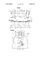
- FIG. 1 is a sectional view showing an embodiment of the invention.
- FIG. 2 is a sectional view taken on line A-B of FIG. 1.
- a fixed packing 6 is attached to the groove 15 of a fixed vane 4, which is attached to a cylinder 2 with a bolt 11.
- a slidable packing 7 is attached to the groove 16 of a moving vane 5, which is attached to a shaft 3 with a bolt 10.
- Packing 6 and 7 both have radial portions that are connected to extend continuously around respective vanes 4 and 5.
- each of the seal plates 8 is arranged with its periphery slightly compressed by the inner surface of the cylinder 2 in the radial direction thereof while the middle hole thereof slightly expands from the outer circumferential surface of the cylinder portion of a shaft 3.
- the shaft 3 is rotatably supported by a bearing 9 in the middle of the cylinder 2.
- the inner circumferential face of the seal plate 8 and the cylinder surface of the shaft 3 are slidably engaged.
- Each of end covers 1 disposed at both ends is combined with the cylinder 2 by means of bolts 14.
- the cylinder 2 is provided with inlet and outlet ports 12 and 13 for a fluid.
- the shaft which has the moving vane 5 mounted thereon is arranged to be rotatable in the right and left directions according as the fluid is allowed to flow in and out through the fluid inlet and outlet ports 12 and 13.
- a feature of the invention resides in the arrangement of each seal plate 8.
- the seal plate 8 has the outer circumferential edge 17 and the inner circumferential edge 18 thereof sharply formed and is set in position with some degree of deformation (compression) thereon in the radial direction.
- the arrangement prevents any leakage from occurring between the cylinder surface and the pressed contact face of the seal plate 8 both in the axial and circumferential directions.
- the faces adjoining the packings 6 and 7 are arranged to be perfectly continuous. In this case, deformation inflicted on the seal plate 8 by fluid pressure is only in the direction of plate thickness thereof and, since the outer and inner circumferential faces of the seal plate 8 are slidable in the direction of the plate thickness, the edge portions 17 and 18 of the seal plate remain undeformed.
- the seal plate 8 according to the present invention is made of a material preferably selected from the group consisting of nylon, polyethylene of ultrahigh molecular weight (UHMW), poly-urethane rubber, etc.
- Conceivable materials usable for this purpose include a complex consisting of polyurethane rubber and fluoro-resin, a complex consisting of a metal and a synthetic rubber and the like.
Abstract
A vane-type rotary actuator in which a disc like seal member made of an elastic material with a hole provided in the middle thereof is pressed in place in contact with a flange surface. With seal material thus somewhat deformed in the radial direction thereof, pressure required for sealing is generated at the inner surface of a cylinder and the outer surface of a shaft cylinder.
Description
This is a continuation of application Ser. No. 389,928 filed June 18, 1982 now abandoned.
This invention relates to a vane-type rotary actuator.
It is an object of the invention to provide a vane-type rotary actuator in which leakage from the outer circumference of a slidably arranged packing is perfectly prevented by forming a continuous sliding surface which has the same cross-section as the outer circumference of the packing.
The object and features of the invention will become apparent from the following detailed description of a preferred embodiment thereof taken in connection with the accompanying drawings.
FIG. 1 is a sectional view showing an embodiment of the invention.
FIG. 2 is a sectional view taken on line A-B of FIG. 1.
Referring to FIG. 2, a fixed packing 6 is attached to the groove 15 of a fixed vane 4, which is attached to a cylinder 2 with a bolt 11. A slidable packing 7 is attached to the groove 16 of a moving vane 5, which is attached to a shaft 3 with a bolt 10. Packing 6 and 7 both have radial portions that are connected to extend continuously around respective vanes 4 and 5.
Referring now to FIG. 1, each of the seal plates 8 is arranged with its periphery slightly compressed by the inner surface of the cylinder 2 in the radial direction thereof while the middle hole thereof slightly expands from the outer circumferential surface of the cylinder portion of a shaft 3. The shaft 3 is rotatably supported by a bearing 9 in the middle of the cylinder 2. The inner circumferential face of the seal plate 8 and the cylinder surface of the shaft 3 are slidably engaged. Each of end covers 1 disposed at both ends is combined with the cylinder 2 by means of bolts 14.
Again referring to FIG. 2, the cylinder 2 is provided with inlet and outlet ports 12 and 13 for a fluid. The shaft which has the moving vane 5 mounted thereon is arranged to be rotatable in the right and left directions according as the fluid is allowed to flow in and out through the fluid inlet and outlet ports 12 and 13.
A feature of the invention resides in the arrangement of each seal plate 8. The seal plate 8 has the outer circumferential edge 17 and the inner circumferential edge 18 thereof sharply formed and is set in position with some degree of deformation (compression) thereon in the radial direction. The arrangement prevents any leakage from occurring between the cylinder surface and the pressed contact face of the seal plate 8 both in the axial and circumferential directions. The faces adjoining the packings 6 and 7 are arranged to be perfectly continuous. In this case, deformation inflicted on the seal plate 8 by fluid pressure is only in the direction of plate thickness thereof and, since the outer and inner circumferential faces of the seal plate 8 are slidable in the direction of the plate thickness, the edge portions 17 and 18 of the seal plate remain undeformed.
Further, an eccentric motion of the shaft 3 due to machining tolerance and a clearance of the bearing 9 is absorbed by elastic deformation of the seal plate 8 in the radial direction thereof. Therefore, the continuous faces of the seal plate 8 remains undisturbed by such an eccentric motion.
The seal plate 8 according to the present invention is made of a material preferably selected from the group consisting of nylon, polyethylene of ultrahigh molecular weight (UHMW), poly-urethane rubber, etc. Conceivable materials usable for this purpose include a complex consisting of polyurethane rubber and fluoro-resin, a complex consisting of a metal and a synthetic rubber and the like.
Claims (2)
1. A vane-type rotary actuator comprising:
a cylindrical housing defining a cylindrical space having an axial direction and a radial direction, said housing defining an axially extending cylindrical metal wall extending around said cylindrical space and a pair of spaced apart radially extending radial metal walls on opposite ends of said cylindrical space;
a shaft having an outer axially extending metal shaft surface, said shaft rotatably mounted to said cylindrical housing extending through a center of said cylindrical space, said cylindrical metal wall and said outer metal shaft surface defining an annular vane space therebetween, said pair of radial metal walls extending between said cylindrical metal wall and said metal outer shaft surface and bounding opposite ends of said annular vane space;
a pair of radially extending seal plates each engaged over a respective one of said radial metal walls, each seal plate being made of elastic material and being radially elastically compressed in position by said cylindrical metal wall, each seal plate having an outer cylindrical surface compressedly engaged against said cylindrical metal wall and an inner cylindrical surface defining a hole through said seal plate and compressedly engaged against said outer metal shaft surface, said seal plates having radial planar walls facing said cylindrical space and against which said fixed packing and said slidable packing bear, said seal plates being each made of a material chose from the group consisting of nylon, UHMW polyethylene, poly-urethane rubber, a complex of poly-urethane rubber and fluoro-resin, and a complex of metal and synthetic rubber;
a fixed vane connected to said fixed cylindrical housing an extending into said vane space;
a fixed packing connected to said fixed vane having an axially extending portion engaged against said outer metal shaft surface and a pair of radially extending portions connected to said axially extending portion each bearing against one of said seal plates;
a movable vane connected to said shaft and extending into said vane space;
a slidable packing connected to said movable vane having an axially extending portion bearing against said cylindrical metal wall and a pair of radially extending portions connected to said axially extending portion and each bearing against one of said seal plates;
said fixed packing including a second axially extending portion bearing against said cylindrical metal wall and connected to said pair of radially extending portions of said fixed packing to form a closed packing around said fixed vane, said slidable packing including a second axially extending portion bearing against said outer metal shaft surface and connected to said pair of radially extending portions of said slidable packing to form a closed packing around said movable vane.
2. An actuator according to claim 1, including bearing members connected between said shaft and said housing for rotatably mounting said shaft to said housing.
Priority Applications (1)
| Application Number | Priority Date | Filing Date | Title |
|---|---|---|---|
| US06/622,659 US4565119A (en) | 1982-06-18 | 1984-06-20 | Vane-type rotary actuator |
Applications Claiming Priority (2)
| Application Number | Priority Date | Filing Date | Title |
|---|---|---|---|
| US38992882A | 1982-06-18 | 1982-06-18 | |
| US06/622,659 US4565119A (en) | 1982-06-18 | 1984-06-20 | Vane-type rotary actuator |
Related Parent Applications (1)
| Application Number | Title | Priority Date | Filing Date |
|---|---|---|---|
| US38992882A Continuation | 1982-06-18 | 1982-06-18 |
Publications (1)
| Publication Number | Publication Date |
|---|---|
| US4565119A true US4565119A (en) | 1986-01-21 |
Family
ID=27012914
Family Applications (1)
| Application Number | Title | Priority Date | Filing Date |
|---|---|---|---|
| US06/622,659 Expired - Fee Related US4565119A (en) | 1982-06-18 | 1984-06-20 | Vane-type rotary actuator |
Country Status (1)
| Country | Link |
|---|---|
| US (1) | US4565119A (en) |
Cited By (11)
| Publication number | Priority date | Publication date | Assignee | Title |
|---|---|---|---|---|
| US4774875A (en) * | 1987-08-20 | 1988-10-04 | Turn Act Inc. | Actuator seal arrangement |
| US4817504A (en) * | 1984-07-20 | 1989-04-04 | Tol-O-Matic, Inc. | Oscillatory actuator with direct contact shaft-shoulder to end cap seal |
| US5125632A (en) * | 1991-01-29 | 1992-06-30 | John A. Blatt | Rotary actuated workpiece holder |
| US5440970A (en) * | 1994-09-21 | 1995-08-15 | Caterpillar Inc. | Hydraulic rotary actuator |
| US5809955A (en) * | 1996-04-10 | 1998-09-22 | Mitsubishi Jidosha Kogyo Kabushiki Kaisha | Hydraulic actuator and variable valve driving mechanism making use of the same |
| US5956901A (en) * | 1997-06-24 | 1999-09-28 | Northrop Grumman Corporation | Gas driven hatch cover assembly |
| US5979163A (en) * | 1997-12-29 | 1999-11-09 | Circular Motion Controls, Inc. | Rotationally pivotal motion controller |
| US20060162548A1 (en) * | 2005-01-27 | 2006-07-27 | 2051172 Ontario Inc. | Rotary hydraulic cylinder |
| US20140271296A1 (en) * | 2013-03-14 | 2014-09-18 | Woodward, Inc. | No Corner Seal Rotary Vane Actuator |
| US9732771B2 (en) | 2013-02-06 | 2017-08-15 | Woodward, Inc. | Hydraulic rotary actuator |
| US9957831B2 (en) | 2014-07-31 | 2018-05-01 | The Boeing Company | Systems, methods, and apparatus for rotary vane actuators |
Citations (9)
| Publication number | Priority date | Publication date | Assignee | Title |
|---|---|---|---|---|
| US2189088A (en) * | 1935-11-29 | 1940-02-06 | Ernest L Thompson | Fluid pressure motor |
| US3008425A (en) * | 1960-06-13 | 1961-11-14 | Chambers George Harold | Gear pump seal |
| US3032020A (en) * | 1960-04-04 | 1962-05-01 | Konstruktioner & Experiment A | Hydraulic servomotor |
| US3049103A (en) * | 1961-05-01 | 1962-08-14 | Pacific Valves Inc | Pressure actuated valve control |
| US3359871A (en) * | 1965-10-22 | 1967-12-26 | Houdaille Industries Inc | Rotary actuator hub seal |
| US3737169A (en) * | 1971-05-13 | 1973-06-05 | Federal Mogul Corp | Gasket material and method of making same |
| US3750535A (en) * | 1970-10-13 | 1973-08-07 | Chukyo Gijutsu Center Kk | Rotary actuator |
| US3919448A (en) * | 1971-09-13 | 1975-11-11 | Chicago Rawhide Mfg Co | Modified elastomeric compositions, method and oil seals made therefrom |
| US4345509A (en) * | 1980-06-23 | 1982-08-24 | Caterpillar Tractor Co. | Contaminant trap for fluid operated rotary actuator |
-
1984
- 1984-06-20 US US06/622,659 patent/US4565119A/en not_active Expired - Fee Related
Patent Citations (9)
| Publication number | Priority date | Publication date | Assignee | Title |
|---|---|---|---|---|
| US2189088A (en) * | 1935-11-29 | 1940-02-06 | Ernest L Thompson | Fluid pressure motor |
| US3032020A (en) * | 1960-04-04 | 1962-05-01 | Konstruktioner & Experiment A | Hydraulic servomotor |
| US3008425A (en) * | 1960-06-13 | 1961-11-14 | Chambers George Harold | Gear pump seal |
| US3049103A (en) * | 1961-05-01 | 1962-08-14 | Pacific Valves Inc | Pressure actuated valve control |
| US3359871A (en) * | 1965-10-22 | 1967-12-26 | Houdaille Industries Inc | Rotary actuator hub seal |
| US3750535A (en) * | 1970-10-13 | 1973-08-07 | Chukyo Gijutsu Center Kk | Rotary actuator |
| US3737169A (en) * | 1971-05-13 | 1973-06-05 | Federal Mogul Corp | Gasket material and method of making same |
| US3919448A (en) * | 1971-09-13 | 1975-11-11 | Chicago Rawhide Mfg Co | Modified elastomeric compositions, method and oil seals made therefrom |
| US4345509A (en) * | 1980-06-23 | 1982-08-24 | Caterpillar Tractor Co. | Contaminant trap for fluid operated rotary actuator |
Non-Patent Citations (2)
| Title |
|---|
| Mechanical Properties of Polymers, L. Nielsen, Reinhold Publishing Corp., N.Y., 1962. * |
| Seals and Sealing Handbook, R. Warring, Trade & Technical Press Ltd., England, (date unknown). * |
Cited By (12)
| Publication number | Priority date | Publication date | Assignee | Title |
|---|---|---|---|---|
| US4817504A (en) * | 1984-07-20 | 1989-04-04 | Tol-O-Matic, Inc. | Oscillatory actuator with direct contact shaft-shoulder to end cap seal |
| US4774875A (en) * | 1987-08-20 | 1988-10-04 | Turn Act Inc. | Actuator seal arrangement |
| US5125632A (en) * | 1991-01-29 | 1992-06-30 | John A. Blatt | Rotary actuated workpiece holder |
| US5440970A (en) * | 1994-09-21 | 1995-08-15 | Caterpillar Inc. | Hydraulic rotary actuator |
| US5809955A (en) * | 1996-04-10 | 1998-09-22 | Mitsubishi Jidosha Kogyo Kabushiki Kaisha | Hydraulic actuator and variable valve driving mechanism making use of the same |
| US5956901A (en) * | 1997-06-24 | 1999-09-28 | Northrop Grumman Corporation | Gas driven hatch cover assembly |
| US5979163A (en) * | 1997-12-29 | 1999-11-09 | Circular Motion Controls, Inc. | Rotationally pivotal motion controller |
| US20060162548A1 (en) * | 2005-01-27 | 2006-07-27 | 2051172 Ontario Inc. | Rotary hydraulic cylinder |
| US9732771B2 (en) | 2013-02-06 | 2017-08-15 | Woodward, Inc. | Hydraulic rotary actuator |
| US20140271296A1 (en) * | 2013-03-14 | 2014-09-18 | Woodward, Inc. | No Corner Seal Rotary Vane Actuator |
| US9841021B2 (en) * | 2013-03-14 | 2017-12-12 | Woodward, Inc. | No corner seal rotary vane actuator |
| US9957831B2 (en) | 2014-07-31 | 2018-05-01 | The Boeing Company | Systems, methods, and apparatus for rotary vane actuators |
Similar Documents
| Publication | Publication Date | Title |
|---|---|---|
| JPH0143514Y2 (en) | ||
| US5217233A (en) | Spiral groove seal system for sealing a high pressure gas | |
| EP0076826B1 (en) | Compact scroll-type fluid compressor | |
| US4565119A (en) | Vane-type rotary actuator | |
| US5228784A (en) | Squeeze film damper composite ring seal | |
| US5542829A (en) | Scroll compressor | |
| US4981423A (en) | Hydraulic motor with wobble-stick and brake assembly | |
| JPH0127272B2 (en) | ||
| CA1073742A (en) | Gerotor gearset device | |
| US5713578A (en) | Hydraulic sealing device | |
| US5085521A (en) | Squeeze film damper seal | |
| US7273004B2 (en) | Reciprocating machine | |
| EP0145205B1 (en) | Fluid pressure device and improved shaft seal | |
| US5624248A (en) | Gerotor motor and improved balancing plate seal therefor | |
| US4495856A (en) | Rotary actuator | |
| US4153258A (en) | Packing seal | |
| US3767333A (en) | Energy converters with crankpin concentric pistons | |
| US5123333A (en) | Seals for housing of a rotary actuator | |
| US5795141A (en) | Scroll type compressor having anti-rotation pin members | |
| US4068986A (en) | Sealing means for radial faces of piston in orbital piston device | |
| AU601217B2 (en) | Pump | |
| EP0733165B1 (en) | Radial journal bearing with slide shoe, and slide shoe for a radial journal bearing | |
| JPH0315668A (en) | Power transmitting device | |
| JPH0348364B2 (en) | ||
| US5417555A (en) | Rotary vane machine having end seal plates |
Legal Events
| Date | Code | Title | Description |
|---|---|---|---|
| FEPP | Fee payment procedure |
Free format text: PAT HLDR NO LONGER CLAIMS SMALL ENT STAT AS INDIV INVENTOR (ORIGINAL EVENT CODE: LSM1); ENTITY STATUS OF PATENT OWNER: LARGE ENTITY |
|
| FPAY | Fee payment |
Year of fee payment: 4 |
|
| FEPP | Fee payment procedure |
Free format text: PAYOR NUMBER ASSIGNED (ORIGINAL EVENT CODE: ASPN); ENTITY STATUS OF PATENT OWNER: LARGE ENTITY |
|
| FPAY | Fee payment |
Year of fee payment: 8 |
|
| REMI | Maintenance fee reminder mailed | ||
| LAPS | Lapse for failure to pay maintenance fees | ||
| FP | Lapsed due to failure to pay maintenance fee |
Effective date: 19980121 |
|
| STCH | Information on status: patent discontinuation |
Free format text: PATENT EXPIRED DUE TO NONPAYMENT OF MAINTENANCE FEES UNDER 37 CFR 1.362 |