US4561414A - Ball throwing machine - Google Patents
Ball throwing machine Download PDFInfo
- Publication number
- US4561414A US4561414A US06/626,176 US62617684A US4561414A US 4561414 A US4561414 A US 4561414A US 62617684 A US62617684 A US 62617684A US 4561414 A US4561414 A US 4561414A
- Authority
- US
- United States
- Prior art keywords
- ball
- throwing machine
- ball throwing
- machine body
- support means
- Prior art date
- Legal status (The legal status is an assumption and is not a legal conclusion. Google has not performed a legal analysis and makes no representation as to the accuracy of the status listed.)
- Expired - Fee Related
Links
- 239000000463 material Substances 0.000 claims description 4
- 239000011347 resin Substances 0.000 claims description 4
- 229920005989 resin Polymers 0.000 claims description 4
- 239000011295 pitch Substances 0.000 description 11
- 230000036544 posture Effects 0.000 description 2
- JOYRKODLDBILNP-UHFFFAOYSA-N Ethyl urethane Chemical compound CCOC(N)=O JOYRKODLDBILNP-UHFFFAOYSA-N 0.000 description 1
- 238000010276 construction Methods 0.000 description 1
- 230000008878 coupling Effects 0.000 description 1
- 238000010168 coupling process Methods 0.000 description 1
- 238000005859 coupling reaction Methods 0.000 description 1
- 238000009987 spinning Methods 0.000 description 1
Images


Classifications
-
- A—HUMAN NECESSITIES
- A63—SPORTS; GAMES; AMUSEMENTS
- A63B—APPARATUS FOR PHYSICAL TRAINING, GYMNASTICS, SWIMMING, CLIMBING, OR FENCING; BALL GAMES; TRAINING EQUIPMENT
- A63B69/00—Training appliances or apparatus for special sports
- A63B69/40—Stationarily-arranged devices for projecting balls or other bodies
- A63B69/406—Stationarily-arranged devices for projecting balls or other bodies with rotating discs, wheels or pulleys gripping and propelling the balls or bodies by friction
-
- Y—GENERAL TAGGING OF NEW TECHNOLOGICAL DEVELOPMENTS; GENERAL TAGGING OF CROSS-SECTIONAL TECHNOLOGIES SPANNING OVER SEVERAL SECTIONS OF THE IPC; TECHNICAL SUBJECTS COVERED BY FORMER USPC CROSS-REFERENCE ART COLLECTIONS [XRACs] AND DIGESTS
- Y10—TECHNICAL SUBJECTS COVERED BY FORMER USPC
- Y10T—TECHNICAL SUBJECTS COVERED BY FORMER US CLASSIFICATION
- Y10T403/00—Joints and connections
- Y10T403/32—Articulated members
- Y10T403/32254—Lockable at fixed position
- Y10T403/32262—At selected angle
- Y10T403/32311—Ball and socket
Definitions
- This invention relates to a ball throwing machine used for baseball practice, e.g., for practicing batting balls and catching batted balls.
- the ball throwing machine body has a pair of rotatable bodies which are adapted to be rotated in opposite directions and at different speeds relative to each other. Balls are successively nipped between these two rotatable bodies and thrown. In this case, a spin is imparted to the ball to a degree which depends on the difference between the rotative speeds of the rotatable bodies to produce different types of pitches, such as a shoot and a curve. Further, said ball throwing machine body is supported on a base through support means.
- a ball body is mounted to project upwardly from a base.
- the ball throwing machine body is provided with a holder member for holding said ball body, said holder member being adapted to be turnable around the center of the ball body.
- the holder member is so arranged that it is fixed to the ball body in its arbitrary angular position relative to the ball body. And, the turning of the holder member allows the ball throwing machine body to assume various postures.
- pitches are limited in type, so that for example, a pitch which rises just short of the batter, i.e., a hop cannot be obtained.
- An object of this invention is to make it possible to obtain various types of pitches by making it possible to arbitrarily select the direction of spin of the ball when the ball is thrown.
- Another object of the invention is to make it possible to obtain more types of pitches by making it possible to vertically change the ball throwing position.
- a further object of the invention is to increase the durability of an apparatus for producing various types of pitches.
- Still another object of the invention is to simplify the arrangement of an apparatus for producing various types of pitches and to facilitate the operation thereof.
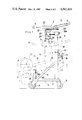
- FIG. 1 is a front view of a ball throwing machine
- FIG. 2 is a side view of the ball throwing machine
- FIG. 3 is a plan view of the ball throwing machine
- FIG. 4 is an enlarged sectional view of a portion of FIG. 1;
- FIG. 5 is a section taken along the line V--V of FIG. 4.
- a ball throwing machine 1 comprises a carriage 2, a pillar member 3 installed on said carriage 2, a ball throwing machine body 4 supported on the upper end of said pillar member 3 for throwing balls 4, and a ball feeder 6.
- the carriage 2 has a base 7 framed in ractangular form when seen in a plan view.
- the base 7 is provided in its front portion with a pair of front wheels 8 and in its rear portion with a pair of rear wheels 9.
- the rear wheels 9 are casters.
- the pillar member 3 forms an extensible, double tube type elevator. That is, a fixed tube 11 of circular cross-section is erected on the rear upper surface of the base 7 and a movable tube 12 of circular cross-section is axially slidably fitted in said fixed tube 11. And, drive means 13 for lifting and lowering the movable tube 12 is provided to enable said movable tube 12 to serve as a lifting-lowering movable part.
- the drive means 13 has a worm gearing 15.
- the worm in this worm gearing 15 is connected to a handle 16, while the worm wheel has a rack pinion 17 connected thereto.
- the movable tube 12 is formed with a rack gear 18.
- the rack gear 18 meshes with said rack pinion 17, so that the movable tube 12 can be lifted and lowered by rotating the handle 16.
- the ball throwing machine body 5 has a pair of disk-like rotatable bodies 21 supported on a support platform 20, and dc motors 23 respectively connected to said rotatable bodies 21 through flexible couplings 22.
- the rotatable bodies are rotated in opposite directions by an unillustrated electric equipment and the balls 4 are nipped between the rotatable bodies 21 and thereby thrown. Further, the rotative speeds of the rotatable bodies 21 can be made different from each other by an unillustrated frequency converter and the resulting spin of the balls 4 changes the balls 4, when thrown, to shoots or curves.
- the ball throwing machine body 5 is supported on the upper end of the movable tube 12 of the pillar member 3 through ball joint type support means 25.
- the upper end of the movable tube 12 is formed with a shaft member 12a of smaller diameter, and a sleeve 26 is turnably fitted on said shaft member 12a.
- a support tube 27 projects from the sleeve 26 forwardly of the ball throwing direction and substantially horizontally, with a ball body 28 supported on the projecting end of said support tube 27.
- the sleeve 26 can be fixed to the shaft member 12a by screwing a stop bolt 26a.
- the support tube 27 may project from the sleeve 26 rearwardly of the ball throwing direction and substantially horizontally.
- a holder member is installed on said support platform 20.
- This holder member has a pair of opposed holder plates 29. These holder plates 29 are fixed at their upper ends to the support platform 20 by bolts. Their lower ends are free and there is provided a clamp 30 for clamping said lower ends.
- the holder plates 29 are formed with circular openings 31 which are axially aligned with each other. And, both sides of said ball body 28 are fitted in said openings 31.
- an annular resin material 32 such as urethane is interposed between the ball body 28 and each opening 31, said resin material 32 being glued to the inner surface of the opening 31.
- the ball body 28 and the holder plates 29 are allowed to turn relative to each other, whereby the ball throwing direction of the ball throwing machine body 5 can be changed to coincide with any desired direction around the ball body. Further, when the clamp 30 is tightened, the ball throwing machine body 5 is fixed to the movable tube 12. In the above case, the resin materials 32 protect the outer surface of the ball body 28 from being damaged by the inner surfaces of the openings 31. As a result, the durability of the support means 25 is improved.
- an angle change plate 34 is pivotally supported on said support platform 20, and an inclined, support sleeve 35 is fixed on said angle change plate 4.
- a guide member 36 for guiding the balls 4 to the nip between the rotatable bodies 21 is fitted in said support sleeve 35 so that it is turnable around the axis of the support sleeve.
- the axis 36a of this guide member 36 is inclined with respect to the axis 35a of the support sleeve 35, so that by turning the guide member 36 around the axis 35a of the support sleeve 35, the angle of inclination of the guide member 36 with respect to the horizontal plane can be arbitrarily set within certain limits.
- a cylindrical support member 38 capable of supporting the ball throwing machine body 5.
- the support member 38 is positioned below the level of the shaft member 12a of the movable tube 12 when the latter is moved to its lowermost position, the upper end of said support member 38 being formed with a shaft member 38a of the same shape as said shaft member 12a.
- the ball throwing machine body 5 can be positioned at a desired height and in a desired posture and hence various types of pitches can be obtained.
- the operation of the ball throwing machine 1 will now be described. If the movable tube 12 is lifted to place the ball throwing machine body 5 at the upper position, overhand pitching becomes possible (as shown in solid lines in the figures). Further, if the movable tube 12 is lowered to place the ball throwing machine body 5 at the lower position, sidearm pitching becomes possible (as shown in dash-double-dot lines in the figures). Further, if the ball throwing machine body 5 is attached to the support member 38, underhand pitching becomes possible (as shown in dash-double-dot lines in the figures).
- the two rotatable bodies 21 are rotated at substantially the same speed at the respective aforesaid positions, a straight ball and a ball which drops suddenly just short of the batting position (so-called fork ball) can be thrown.
- the rotatable bodies 21 are horizontally disposed and rotated at different speeds, a shoot and a curve can be produced, with the ball 4 rotated around its vertical axis.
- the rotatable bodies 21 are vertically disposed as in the above (as shown in dash-dot lines in the figures), it is possible to produce a pitch which drops just short of the batting position (so-called drop) or a pitch which reversely rises (so-called hop) by spinning the ball 4 around its horizontal axis.
- the ball body 28 may be provided on the ball throwing machine body 5 and the holder plates 29 on the base 7.
Landscapes
- Health & Medical Sciences (AREA)
- General Health & Medical Sciences (AREA)
- Physical Education & Sports Medicine (AREA)
- Toys (AREA)
Abstract
Description
Claims (5)
Applications Claiming Priority (4)
| Application Number | Priority Date | Filing Date | Title |
|---|---|---|---|
| JP59-35854[U] | 1984-03-12 | ||
| JP59-35855[U] | 1984-03-12 | ||
| JP3585584U JPS60147471U (en) | 1984-03-12 | 1984-03-12 | Support device for pitching machine body |
| JP3585484U JPS60147470U (en) | 1984-03-12 | 1984-03-12 | pitching machine |
Publications (1)
| Publication Number | Publication Date |
|---|---|
| US4561414A true US4561414A (en) | 1985-12-31 |
Family
ID=26374856
Family Applications (1)
| Application Number | Title | Priority Date | Filing Date |
|---|---|---|---|
| US06/626,176 Expired - Fee Related US4561414A (en) | 1984-03-12 | 1984-06-29 | Ball throwing machine |
Country Status (1)
| Country | Link |
|---|---|
| US (1) | US4561414A (en) |
Cited By (19)
| Publication number | Priority date | Publication date | Assignee | Title |
|---|---|---|---|---|
| US4678189A (en) * | 1985-08-01 | 1987-07-07 | Koss Richard E | Basketball return device |
| US4714248A (en) * | 1985-08-01 | 1987-12-22 | Koss Richard E | Basketball return device |
| US4917527A (en) * | 1988-11-21 | 1990-04-17 | Bollinger William A | Snap-loc coupling device |
| US5127390A (en) * | 1990-11-13 | 1992-07-07 | Paulson Kerry K | Wheel for ball throwing machine |
| US5174533A (en) * | 1991-05-13 | 1992-12-29 | Pryor Products | Adjustable instrument mounting assembly |
| US5437261A (en) * | 1993-10-27 | 1995-08-01 | Jugs, Inc. | Ball pitching device |
| US5890687A (en) * | 1996-07-22 | 1999-04-06 | Pryor Products | Foldable wheeled stand |
| US5964209A (en) * | 1996-12-23 | 1999-10-12 | Boehner; Douglas L. | Volleyball serving apparatus |
| US6237583B1 (en) * | 2000-09-01 | 2001-05-29 | Richard W. Ripley | Baseball pitching device |
| US20040052578A1 (en) * | 2002-09-18 | 2004-03-18 | Pitney Bowes Incorporated | Module latching mechanism for mailing machine |
| US20120097145A1 (en) * | 2010-10-22 | 2012-04-26 | Sheng-Hsiao Lu | Pitching Machine Having Angle and Speed Adjustment Function |
| US20130312723A1 (en) * | 2012-05-28 | 2013-11-28 | Sheng-Hsiao Lu | Rotary Wheel for Ball Pitching machine |
| US8833355B2 (en) | 2011-06-07 | 2014-09-16 | Jugs Sports, Inc. | Pneumatic tire for throwing machine |
| WO2016174484A3 (en) * | 2015-04-29 | 2016-12-08 | KŐRÖSI, Róbert | Ball serving apparatus |
| US9623313B1 (en) * | 2015-12-11 | 2017-04-18 | Sports Attack, LLC | System and method to pitch volleyballs |
| US10843055B2 (en) | 2014-09-23 | 2020-11-24 | Aaron Barnes | Basketball game system |
| US20210031087A1 (en) * | 2019-07-31 | 2021-02-04 | Pierre Juste | Wireless glove controlled soccer goal ball distributor |
| US20220266115A1 (en) * | 2021-02-24 | 2022-08-25 | Michael Robert Valenches | Ball throwing machine and system |
| US20240149129A1 (en) * | 2022-11-03 | 2024-05-09 | Toca Football, Inc. | Launch wheel for a ball-throwing machine |
Citations (6)
| Publication number | Priority date | Publication date | Assignee | Title |
|---|---|---|---|---|
| FR1057682A (en) * | 1951-06-07 | 1954-03-10 | Scythe including an adjustable device to fix its blade to its handle | |
| US3704645A (en) * | 1971-09-01 | 1972-12-05 | C F Martin & Co | Accessory holder for musical instruments of the percussion type |
| US3774584A (en) * | 1972-02-14 | 1973-11-27 | J Paulson | Coacting wheel type ball projecting device |
| US3815892A (en) * | 1972-05-05 | 1974-06-11 | G Tulk | Vise |
| GB2040353A (en) * | 1978-12-06 | 1980-08-28 | Ehrenreich Gmbh & Co Kg A | Step bearing |
| US4323048A (en) * | 1980-07-17 | 1982-04-06 | Kabushiki Kaisha Tokiwa Seisakusho | Ball shooting machine for volleyball practice |
-
1984
- 1984-06-29 US US06/626,176 patent/US4561414A/en not_active Expired - Fee Related
Patent Citations (6)
| Publication number | Priority date | Publication date | Assignee | Title |
|---|---|---|---|---|
| FR1057682A (en) * | 1951-06-07 | 1954-03-10 | Scythe including an adjustable device to fix its blade to its handle | |
| US3704645A (en) * | 1971-09-01 | 1972-12-05 | C F Martin & Co | Accessory holder for musical instruments of the percussion type |
| US3774584A (en) * | 1972-02-14 | 1973-11-27 | J Paulson | Coacting wheel type ball projecting device |
| US3815892A (en) * | 1972-05-05 | 1974-06-11 | G Tulk | Vise |
| GB2040353A (en) * | 1978-12-06 | 1980-08-28 | Ehrenreich Gmbh & Co Kg A | Step bearing |
| US4323048A (en) * | 1980-07-17 | 1982-04-06 | Kabushiki Kaisha Tokiwa Seisakusho | Ball shooting machine for volleyball practice |
Cited By (22)
| Publication number | Priority date | Publication date | Assignee | Title |
|---|---|---|---|---|
| US4678189A (en) * | 1985-08-01 | 1987-07-07 | Koss Richard E | Basketball return device |
| US4714248A (en) * | 1985-08-01 | 1987-12-22 | Koss Richard E | Basketball return device |
| US4917527A (en) * | 1988-11-21 | 1990-04-17 | Bollinger William A | Snap-loc coupling device |
| US5127390A (en) * | 1990-11-13 | 1992-07-07 | Paulson Kerry K | Wheel for ball throwing machine |
| US5174533A (en) * | 1991-05-13 | 1992-12-29 | Pryor Products | Adjustable instrument mounting assembly |
| US5437261A (en) * | 1993-10-27 | 1995-08-01 | Jugs, Inc. | Ball pitching device |
| US5890687A (en) * | 1996-07-22 | 1999-04-06 | Pryor Products | Foldable wheeled stand |
| US5964209A (en) * | 1996-12-23 | 1999-10-12 | Boehner; Douglas L. | Volleyball serving apparatus |
| US6237583B1 (en) * | 2000-09-01 | 2001-05-29 | Richard W. Ripley | Baseball pitching device |
| US6739793B2 (en) * | 2002-09-18 | 2004-05-25 | Pitney Bowes Inc. | Module latching mechanism for mailing machine |
| US20040052578A1 (en) * | 2002-09-18 | 2004-03-18 | Pitney Bowes Incorporated | Module latching mechanism for mailing machine |
| US20120097145A1 (en) * | 2010-10-22 | 2012-04-26 | Sheng-Hsiao Lu | Pitching Machine Having Angle and Speed Adjustment Function |
| US8833355B2 (en) | 2011-06-07 | 2014-09-16 | Jugs Sports, Inc. | Pneumatic tire for throwing machine |
| US20130312723A1 (en) * | 2012-05-28 | 2013-11-28 | Sheng-Hsiao Lu | Rotary Wheel for Ball Pitching machine |
| US8707942B2 (en) * | 2012-05-28 | 2014-04-29 | Sheng-Hsiao Lu | Rotary wheel for ball pitching machine |
| US10843055B2 (en) | 2014-09-23 | 2020-11-24 | Aaron Barnes | Basketball game system |
| WO2016174484A3 (en) * | 2015-04-29 | 2016-12-08 | KŐRÖSI, Róbert | Ball serving apparatus |
| US9623313B1 (en) * | 2015-12-11 | 2017-04-18 | Sports Attack, LLC | System and method to pitch volleyballs |
| US20210031087A1 (en) * | 2019-07-31 | 2021-02-04 | Pierre Juste | Wireless glove controlled soccer goal ball distributor |
| US20220266115A1 (en) * | 2021-02-24 | 2022-08-25 | Michael Robert Valenches | Ball throwing machine and system |
| US11771976B2 (en) * | 2021-02-24 | 2023-10-03 | Michael Robert Valenches | Ball throwing machine and system |
| US20240149129A1 (en) * | 2022-11-03 | 2024-05-09 | Toca Football, Inc. | Launch wheel for a ball-throwing machine |
Similar Documents
| Publication | Publication Date | Title |
|---|---|---|
| US4561414A (en) | Ball throwing machine | |
| US6440013B1 (en) | Pitching machine | |
| US3724437A (en) | Ball throwing machine | |
| US5437261A (en) | Ball pitching device | |
| USRE30703E (en) | Ball throwing device with rotary wheel, and pad means for compressing a ball against the wheel | |
| US4323048A (en) | Ball shooting machine for volleyball practice | |
| US4383686A (en) | Batting tee | |
| US4823763A (en) | Ball projecting apparatus | |
| US4080950A (en) | Ball throwing device | |
| US3408070A (en) | Revolving baseball toy comprising magnetic clutch means | |
| US6402640B1 (en) | Ball throwing device | |
| JPH0470035B2 (en) | ||
| US7479074B1 (en) | Batting tee | |
| JPS5829647A (en) | Device for joining ply of tire | |
| US4872675A (en) | Baseball pitching device | |
| US3261340A (en) | Ball-pitching machine with trajectory-controlling means | |
| US4195614A (en) | Rotatable coacting members for projecting a ball | |
| JPH0413015Y2 (en) | ||
| KR101922672B1 (en) | Pitching Device | |
| JPH0511888Y2 (en) | ||
| JPH0413014Y2 (en) | ||
| DE4236349C2 (en) | Tumbler screening machine with rotary actuator adjustment of the inclination | |
| KR20140029337A (en) | Apparatus for controlling the angle of golfer's site | |
| CN212575603U (en) | Football shooting toy | |
| CN110251923B (en) | Tennis service trolley |
Legal Events
| Date | Code | Title | Description |
|---|---|---|---|
| FEPP | Fee payment procedure |
Free format text: PAYOR NUMBER ASSIGNED (ORIGINAL EVENT CODE: ASPN); ENTITY STATUS OF PATENT OWNER: SMALL ENTITY |
|
| FPAY | Fee payment |
Year of fee payment: 4 |
|
| FEPP | Fee payment procedure |
Free format text: PAYER NUMBER DE-ASSIGNED (ORIGINAL EVENT CODE: RMPN); ENTITY STATUS OF PATENT OWNER: SMALL ENTITY Free format text: PAYOR NUMBER ASSIGNED (ORIGINAL EVENT CODE: ASPN); ENTITY STATUS OF PATENT OWNER: SMALL ENTITY |
|
| FEPP | Fee payment procedure |
Free format text: PAYER NUMBER DE-ASSIGNED (ORIGINAL EVENT CODE: RMPN); ENTITY STATUS OF PATENT OWNER: SMALL ENTITY Free format text: PAYOR NUMBER ASSIGNED (ORIGINAL EVENT CODE: ASPN); ENTITY STATUS OF PATENT OWNER: SMALL ENTITY |
|
| FPAY | Fee payment |
Year of fee payment: 8 |
|
| FEPP | Fee payment procedure |
Free format text: PAYER NUMBER DE-ASSIGNED (ORIGINAL EVENT CODE: RMPN); ENTITY STATUS OF PATENT OWNER: SMALL ENTITY Free format text: PAYOR NUMBER ASSIGNED (ORIGINAL EVENT CODE: ASPN); ENTITY STATUS OF PATENT OWNER: SMALL ENTITY |
|
| REMI | Maintenance fee reminder mailed | ||
| LAPS | Lapse for failure to pay maintenance fees | ||
| FP | Lapsed due to failure to pay maintenance fee |
Effective date: 19971231 |
|
| STCH | Information on status: patent discontinuation |
Free format text: PATENT EXPIRED DUE TO NONPAYMENT OF MAINTENANCE FEES UNDER 37 CFR 1.362 |